

Page 1
AudiaEXPI-D
&
AudiaEXPO-D
Digital
Input & Output
Expanders
Operation Manual
Biamp Systems, 10074 S.W. Arctic Drive, Beaverton, Oregon 97005 U.S.A. (503) 641-7287 www.biamp.com
Page 2

blank
16Mar07
Page 3

k
TABLE OF CONTENTS
AudiaEXPI-D - front & rear panels
AudiaEXPO-D - front & rear panels
Encoder/Display Menus
Application
Specifications
Block Diagrams
Warranty
CE Declaration
Safety Information
AudiaEXPI-D & AudiaEXPO-D
INTRODUCTION
pg. 2
pg. 3
pg. 4
pg. 6
pg. 8
pg. 9
pg. 10
pg. 11
pgs. 12~14
AudiaEXPI-D is a digital input expander for AUDIA
audio systems for demanding professional sound installations. AudiaEXPI-D
accepts eight channels of digital audio input and provides eight channels of
digital audio output via CobraNet
centralized system, or it can extend system boundaries by providing inputs in
remote locations. AudiaEXPI-D is represented as a block in AUDIA software,
for easy inclusion into any system design. AudiaEXPI-D may also be used to
provide inputs to other CobraNet compliant systems or devices.
AudiaEXPI-D features include:
♦ 4 AES3 digital input pairs on XLR (xfmr coupled)
♦ SPDIF digital inputs on RCA (channels 1-2 & 3-4)
♦ TOSLINK digital inputs (channels 5-6 & 7-8)
♦ 8 channels of digital audio output via CobraNet
♦ Word Clock output on BNC connector
♦ rotary encoder with LCD for programming/setup
♦ logic inputs for recalling preset configurations
♦ included as block in AUDIA system design software
♦ may be used with any CobraNet compliant system
♦ CE marked and UL listed power source
AudiaEXPO-D is a digital output expander for AUDIA
digital audio systems for demanding professional sound installations.
AudiaEXPO-D accepts eight digital audio input signals via CobraNet
provides eight channels of digital audio output. AudiaEXPO-D can simply add
outputs to a centralized system, or it can extend system boundaries by
providing outputs in remote locations. AudiaEXPO-D is represented as a bloc
in AUDIA software, for easy inclusion into any system design. AudiaEXPO-D
may also be used to provide outputs from other CobraNet compliant systems or
devices.
AudiaEXPO-D features include:
♦ 8 channels of digital audio input via CobraNet
♦ 4 AES3 digital output pairs on XLR (xfmr coupled)
♦ SPDIF digital outputs on RCA (channels 1-2 & 3-4)
♦ TOSLINK digital outputs (channels 5-6 & 7-8)
♦ Word Clock output on BNC connector
♦ rotary encoder with LCD for programming/setup
♦ logic inputs for recalling preset configurations
♦ included as block in AUDIA system design software
♦ may be used with any CobraNet compliant system
♦ CE marked and UL listed power source
®
, the benchmark in digital
®
. AudiaEXPI-D can simply add inputs to a
®
, the benchmark in
®
and
1
Page 4

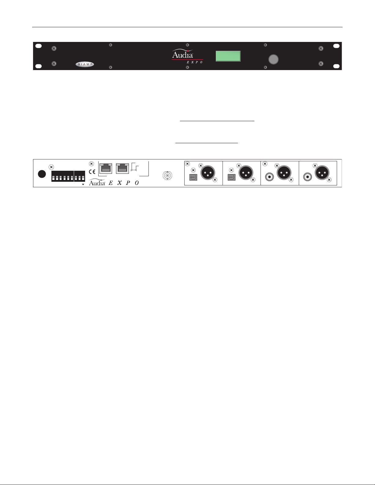
AudiaEXPI-D - Front & Rear Panels
BIAMP
SYSTEMS
Rotary Encoder & LCD Display: This control and display are used for initial setup of the AudiaEXPI unit. When power is first applied to
the unit, the display will cycle through a product description, followed by a title screen. Press the control to enter setup. Rotate the control
to make a selection, then press the control again to edit that selection. Additional levels of selection may be available using this same
routine. Some edits will require a choice of 'OK' or 'CANCEL. Some selections are only informational, and cannot be edited. Select
'BACK' to return to a previous level, and select '→' to advance. Primary selections are as follows
: COBRANET PARAMTRS (CobraNet
bundle, latency, & sample rate settings); AES3 PARAMTRS (various digital audio settings); WORD CLK OUTPUT (clock source); LOGIC
PRESETS (store/recall logic input presets); PASSWORD PROTECT (prevent tampering); TITLE DISPLAY (create custom title);
HARDWARE STATUS (display operational information); ABOUT (display serial# and version information). Menu information on page 4
.
secondary
27V
50/60 Hz
12 watts
class 2 wiring
~
123456 78
BIAMP SYSTEMS
designed and assembled in the USA
www.biamp.com
logic inputs
primary
CobraNet® connections only
in use / conductor
link / activity
LEDs
U.S. pat. no. 4,922,536
-D
word clock out
PUSH PUSH PUSHPUSH
inputs
7-8
TOSLINK AES3
inputs
5-6
inputs
3-4
SPDIF AES3SPDIF AES3TOSLINK AES3
inputs
1-2
Digital Inputs: The four female XLR connectors provide a total of eight AES3 digital audio inputs in channel pairs (1-2, 3-4, 5-6, 7-8).
AES3 inputs are transformer coupled and should be wired using 110 ohm shielded-pair digital audio cable, with pin 2 (+), pin 3 (-), & pin 1
(ground). Input pairs 1-2 & 3-4 may each be selected for SPDIF input, and input pairs 5-6 & 7-8 may each be selected for TOSLINK input
(see Rotary Encoder above). SPDIF inputs are provided on RCA jacks and should be wired using 75 ohm coaxial cable, with Tip (+) and
Sleeve (ground). TOSLINK inputs utilize optical digital audio patch cables.
Word Clock Out: This BNC connector provides clock output from either CobraNet or a selected input source (see Rotary Encoder
above).
Logic Inputs: These eight Logic Inputs allow remote control of preset configurations. Preset configurations may be assigned to Logic
Inputs 1~8 using the front panel Rotary Encoder (see above), and can then be selected via external contact-closures (wired from the
corresponding logic inputs to ground).
CobraNet: These two RJ45 connectors provide the CobraNet digital audio interface. CobraNet allows multiple AUDIA units to share
digital audio (and DSP resources) on a system network. This also allows AUDIA units to be used with CobraNet compliant devices from
other manufacturers. A 10/100Base-T Ethernet switch (not hub) is required when networking multiple units. The maximum distance
between any unit and an Ethernet switch is 100 meters. Additional Ethernet switches, or even fiber-optics, can be used to further extend
distances between units on a system network. The primary and secondary CobraNet ports are redundant. CobraNet supports 64
channels of digital audio (32-in & 32-out) over Fast Ethernet, using CAT-5 cable. CobraNet transmits (32) channels of digital audio on (4)
'bundles' of (8) channels each. The same is true for receiving digital audio over CobraNet. Bundle numbers are used to determine where
digital audio is transmitted and received. Typically, 'unicast' bundle numbers (256~61,439) are used to exchange digital audio between two
specific devices. With 'unicast' bundles, each CobraNet device can transmit to no more than (4) other devices within a network. With
'multicast' bundle numbers (1~255), digital audio can be exchanged with multiple devices. Due to network delay, CobraNet has a limitation
of seven (7) 'hops' (one-way transmissions) within a network.
In order to integrate AudiaEXPI-D into a AUDIA system, an EXPI-D (or CobraNet) input block must first be placed into the design layout.
AUDIA units intended to receive digital audio from the AudiaEXPI-D must have their CobraNet jacks connected to the same network. Both
the AudiaEXPI-D unit (hardware) and the EXPI-D input block (software) must be assigned matching bundle numbers, before digital audio
can be successfully exchanged. AudiaEXPI-D bundle number assignment can be changed in real-time to allow routing of digital audio to
different EXPI-D input blocks within the system. CobraNet Latency settings must be identical in all devices, system-wide. Also, unicast
and multicast bundle numbers can be used to route digital audio to individual or multiple EXPI-D input blocks. Similar considerations may
also apply when using AudiaEXPI-D with other CobraNet compliant systems or devices. AudiaEXPI-D and AudiaEXPO-D can exchange
digital audio directly (outside of a system network) using either a simple 'cross-over' CAT5 cable or an Ethernet switch.
2
Page 5
AudiaEXPO-D - Front & Rear Panels
BIAMP
SYSTEMS
-D
Rotary Encoder & LCD Display: This control and display are used for initial setup of the AudiaEXPI unit. When power is first applied to
the unit, the display will cycle through a product description, followed by a title screen. Press the control to enter setup. Rotate the control
to make a selection, then press the control again to edit that selection. Additional levels of selection may be available using this same
routine. Some edits will require a choice of 'OK' or 'CANCEL. Some selections are only informational, and cannot be edited. Select
'BACK' to return to a previous level, and select '→' to advance. Primary selections are as follows
bundle, latency, & sample rate settings); AES3 PARAMTRS (various digital audio settings); LOGIC PRESETS (store/recall logic input
presets); PASSWORD PROTECT (prevent tampering); TITLE DISPLAY (create custom title); HARDWARE STATUS (display operational
information); ABOUT (display serial# and version information). Menu information on page 4
secondary
27V
50/60 Hz
12 watts
class 2 wiring
~
123456 78
BIAMP SYSTEMS
designed and assembled in the USA
www.biamp.com
logic inputs
primary
CobraNet® connections only
in use / conductor
link / activity
LEDs
U.S. pat. no. 4,922,536
-D
word clock out
TOSLINK AES3
outputs
7-8
Digital Outputs: The four male XLR connectors provide a total of eight AES3 digital audio outputs in channel pairs (1-2, 3-4, 5-6, 7-8).
AES3 outputs are transformer coupled and should be wired using 110 ohm shielded-pair digital audio cable, with pin 2 (+), pin 3 (-), & pin 1
(ground). Output pairs 1-2 & 3-4 are also available as SPDIF outputs, and output pairs 5-6 & 7-8 are also available as TOSLINK outputs.
SPDIF outputs are provided on RCA jacks and should be wired using 75 ohm coaxial cable, with Tip (+) and Sleeve (ground). TOSLINK
outputs utilize optical digital audio patch cables.
Word Clock Out: This BNC connector provides clock output from CobraNet.
Logic Inputs: These eight Logic Inputs allow remote control of preset configurations. Preset configurations may be assigned to Logic
Inputs 1~8 using the front panel Rotary Encoder (see above), and can then be selected via external contact-closures (wired from the
corresponding logic inputs to ground).
CobraNet: These two RJ45 connectors provide the CobraNet digital audio interface. CobraNet allows multiple AUDIA units to share
digital audio (and DSP resources) on a system network. This also allows AUDIA units to be used with CobraNet compliant devices from
other manufacturers. A 10/100Base-T Ethernet switch (not hub) is required when networking multiple units. The maximum distance
between any unit and an Ethernet switch is 100 meters. Additional Ethernet switches, or even fiber-optics, can be used to further extend
distances between units on a system network. The primary and secondary CobraNet ports are redundant. CobraNet supports 64
channels of digital audio (32-in & 32-out) over Fast Ethernet, using CAT-5 cable. CobraNet transmits (32) channels of digital audio on (4)
'bundles' of (8) channels each. The same is true for receiving digital audio over CobraNet. Bundle numbers are used to determine where
digital audio is transmitted and received. Typically, 'unicast' bundle numbers (256~61,439) are used to exchange digital audio between two
specific devices. With 'unicast' bundles, each CobraNet device can transmit to no more than (4) other devices within a network. With
'multicast' bundle numbers (1~255), digital audio can be exchanged with multiple devices. Due to network delay, CobraNet has a limitation
of seven (7) 'hops' (one-way transmissions) within a network.
In order to integrate AudiaEXPO-D into a AUDIA system, an EXPO-D (or CobraNet) output block must first be placed into the design
layout. AUDIA units intended to transmit digital audio to the AudiaEXPO-D must have their CobraNet jacks connected to the same
network. Both the AudiaEXPO-D unit (hardware) and the EXPO-D output block (software) must be assigned matching bundle numbers,
before digital audio can be successfully exchanged. AudiaEXPO-D bundle number assignment can be changed in real-time to allow
access to digital audio from different EXPO-D output blocks within the system. CobraNet Latency settings must be identical in all devices,
system-wide. Also, unicast and multicast bundle numbers can be used to access digital audio from individual or multiple EXPO-D output
blocks. Similar considerations may apply when using AudiaEXPO-D with other CobraNet compliant systems or devices. AudiaEXPI-D and
AudiaEXPO-D can exchange digital audio directly (outside of a system network) using either a simple 'cross-over' CAT5 cable or an
Ethernet switch.
: COBRANET PARAMTRS (CobraNet
.
outputs
5-6
outputs
3-4
SPDIF AES3SPDIF AES3TOSLINK AES3
outputs
1-2
3
Page 6

ENCODER/DISPLAY MENUS
At power-up, the display will flash three product ID screens, ending on a customizable Title screen. Pressing the encoder while on the Title
screen will reveal the Main Menu. Rotate encoder to cycle through available selections. Press encoder to make selections or enter data.
MAIN MENU
PASSWORD PROTECT - TITLE DISPLAY - HARDWARE STATUS - ABOUT
COBRANET PARAMTRS
BUNDLE NUMBER - COBRANET LATENCY - COBRANET SAMPL RT
BUNDLE NUMBER
('unicast' bundle numbers = 256 ~ 61,439; 'multicast' bundle numbers = 1 ~ 255)
COBRANET LATENCY
(5.33mS default; 1.33mS; 2.66mS)
COBRANET SAMPL RT
(48kHz default; 96kHz)
AES3 PARAMTRS
MUTE - SOURCE - FORMAT - EMPHASIS - SAMPLE RT - SIGNAL - COPYGRD
MUTE
('N' = un-muted default; 'Y' = muted)
SOURCE
('A' = AES3 default; 'S' = SPDIF; 'T' = TOSLINK) (EXPI-D only)
FORMAT
('P' = Professional default; 'C' = Consumer) (EXPO-D selection; EXPI-D display only)
EMPHASIS
('N' = Off default; 'Y' = On; '?' = EXPI-D input source emphasis unknown) (EXPO-D selection; EXPI-D display only)
SAMPLE RT
(32kHz; 44kHz; 48kHz; 82kHz; 96kHz; '?' = EXPI-D input source sample rate unknown) (display only)
SIGNAL
('Y' = carrier present; 'N' = carrier not detected) (EXPI-D display only)
COPYGRD
NOTE: It is illegal to make unauthorized copies of copy guarded material.
('N' = Off default; 'Y' = On; '?' = EXPI-D input source copy guard unknown; 'x' = not available for Professional format)
: COBRANET PARAMTRS - AES3 PARAMTRS - WORD CLK OUTPUT (EXPI-D only) - LOGIC PRESETS -
: Establishes CobraNet parameters for CURRENT operation and for LOGIC 1~8 (presets).
: Assigns CobraNet bundle number for current operation or selected logic preset. Bundle numbers must
match those of the corresponding blocks within the AUDIA system design (or other CobraNet devices being used).
: Selects appropriate CobraNet latency for current operation or selected logic preset. CobraNet latency
must match that of the corresponding AUDIA system (or other CobraNet devices being used).
: Selects desired CobraNet sample rate for current operation or selected logic preset. CobraNet sample
rate must match that of the corresponding AUDIA system (or other CobraNet devices being used).
: Establishes digital audio parameters for CURRENT operation and for LOGIC 1~8 (presets).
: Assigns muting of digital audio pairs (1-2; 3-4; 5-6; 7-8) for current operation or selected logic preset.
: Selects source of digital audio input pairs (1-2; 3-4; 5-6; 7-8) for current operation or selected logic preset.
: Selects / displays format of digital audio pairs (1-2; 3-4; 5-6; 7-8) for current operation or selected logic preset. EXPI-
D detects format of the digital audio input sources. EXPO-D settings must be compatible with receiving devices.
: Selects / displays emphasis of digital audio pairs (1-2; 3-4; 5-6; 7-8) for current operation or selected logic preset.
EXPI-D detects emphasis of the digital audio input sources. EXPO-D settings must be compatible with source signals.
: Displays sample rate of digital audio pairs (1-2; 3-4; 5-6; 7-8) for current operation. EXPI-D detects sample rate of
the digital audio input sources. EXPO-D simply displays the selected CobraNet sample rate.
: Displays presence of carrier signal at digital audio input pairs (1-2; 3-4; 5-6; 7-8) for current operation.
: Selects / displays copy guard of digital audio pairs (1-2; 3-4; 5-6; 7-8) for current operation or selected logic preset.
EXPI-D detects copy guard of the digital audio input sources. EXPO-D settings must be compatible with source signals.
4
Page 7

ENCODER/DISPLAY MENUS
WORD CLK OUTPUT (EXPI-D only)
('CBRNET' default; 'INP 12'; 'INP 34'; 'INP 56'; 'INP 78')
LOGIC PRESETS
RECALL - SAVE TO
PASSWORD PROTECT
LOCK (SET PWRD) - UNLOCK (ENT PWRD) - CLEAR
TITLE DISPLAY
('TITLE 1' = top line / 8 characters; 'TITLE 2' = bottom line / 8 characters)
HARDWARE STATUS
3.3V PWR - COBRANET - TEMPRATR - FAN - CLK OUTP AUDIO 12 - AUDIO 34 - AUDIO 56 - AUDIO 78
ABOUT
SERIAL # - FWARE V. - BOOT V. - CM1 V. (CobraNet) - MAC (CobraNet module ethernet address)
: Displays serial number and various version related information.
: Recalls LOGIC 1~8 presets into current settings or saves current settings into LOGIC 1~8 presets.
: Sets and clears password protection. Locks and un-locks access to settings via established password.
: Establishes a customized Title screen to be displayed at power-up and after exiting setup menus.
: Displays operational status of various hardware parameters.
: Selects word clock source for CURRENT operation and for LOGIC 1~8 (presets).
5
Page 8
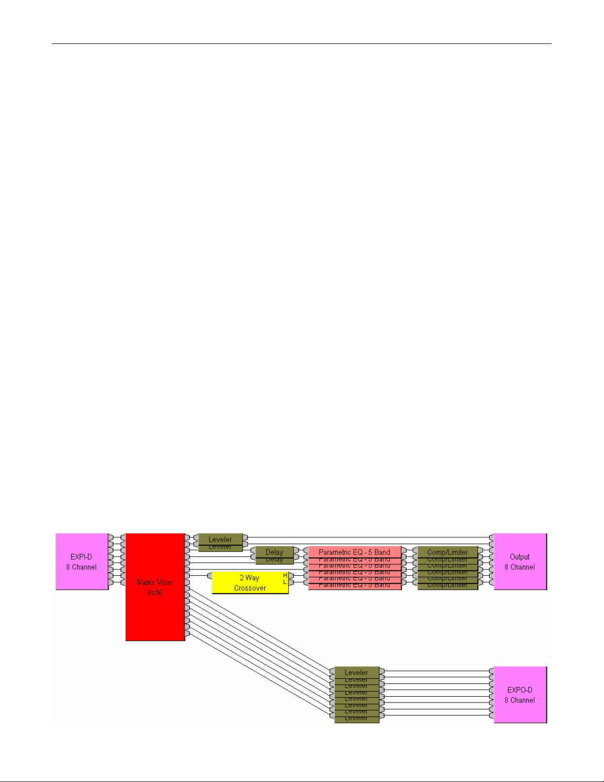
APPLICATION
This application demonstrates the use of AUDIA in a house of worship. This is a networked system using one AudiaFLEX 8-Output CM
unit, an AudiaEXPI-D 8-Input Digital Expander unit, and an AudiaEXPO-D 8-Output Digital Expander unit (eight digital inputs, eight digital
outputs, eight analog outputs, CobraNet). An example system diagram is shown on the opposite page, and a representative design layout
is shown at the bottom of this page.
Multiple microphones, for speech and music performance, are connected to inputs of a digital mixing console located at the Front-of-House
mixing position. The console provides multiple mixes, including effects, which are appropriate for as many as eight different outputs: Main
Speakers (HF & LF), Balcony Speakers, Under-Balcony Speakers, Stage Monitors (1 & 2), Recording, and Hearing Assistance. Eight
digital audio feeds, from mixing console outputs and other 'playback' devices, are connected to inputs of the AudiaEXPI-D unit, which is
located near the mixing console. These signals are then sent via CobraNet to the AudiaFLEX unit, which is located backstage. The
AudiaFLEX unit provides all necessary signal processing for each of the system outputs, before feeding an MCA8150 power amplifier
located in the same equipment rack.
The MCA8150 amplifier uses four channels bridged in pairs, creating two outputs of 300 watts each. These outputs are driving the Main
speaker systems (HF & LF). The MCA8150 amplifier also uses four individual channels, of 150 watts each, to drive the Balcony, UnderBalcony, Monitor 1, & Monitor 2 speaker systems. TDT150 transformers are installed internally for the outputs driving the Balcony and
Under-Balcony systems, which are utilizing 70V distributed speakers.
The AudiaFLEX unit also provides eight channels of digital audio, via CobraNet, to the AudiaEXPO-D. The AudiaEXPO-D then provides
digital audio outputs at a broadcast/media feed panel.
CobraNet from the three AUDIA units is tied together through an Ethernet switch. This allows sharing of digital audio signals on a network.
The maximum distance between any AUDIA unit and an Ethernet switch is 300 feet. Therefore, this system can span up to 600 feet
between the backstage and mixing locations. Additional Ethernet switches, or even fiber-optics, can be used to further extend distances
between units on the network. An added benefit to CobraNet is that it affords the necessary isolation to help avoid ground loops between
active components in different locations. CobraNet also saves on the labor and expense of wiring, by transmitting eight channels of digital
audio over a single CAT5 cable.
Of course, all live mixing is done at the console. The AUDIA network provides transportation, routing, and processing of the signals.
AudiaEXPI-D and AudiaEXPO-D units act as a 'digital snake', transmitting digital audio between the backstage, mixing, and
broadcast/media feed locations. The AudiaFLEX unit provides routing and signal processing for the various outputs. In the example
design, parametric EQ and comp/limiting are employed at all speaker outputs. Main outputs include a 2-Way Crossover (separate high-
frequency & low-frequency drivers). Balcony and Under-Balcony outputs include Delay compensation. Recording, Hearing Assistance,
and Broadcast/Media outputs are processed simply with Levelers (for automatic control of recording/broadcast signal levels).
Various remote control options are available. Volume 8, Select 8, and Volume/Select 8 rotary encoder panels may be used to provide
volume adjustments and preset selections. A Logic Box allows system control via external switches, or control of external equipment from
the system itself.
6
Page 9

APPLICATION
AudiaEXPI-D
BIAMP SYSTEMS
designed and assembled in the USA
www.biamp.com
27V
~
50/60 Hz
logic inputs
12 watts
class 2 wiring
12345678
CobraNet
EtherNet Switch
primary
CobraNet® connections only
secondary
in use / conductor
LEDs
U.S. pat. no. 4,922,536
link / activity
word clock out
-D
PUSH PUSH PUSHPUSH
inputs
7-8
TOSLINK AES3
inputs
inputs
5-6
inputs
3-4
1-2
SPDIF AES3SPDIF AES3TOSLINK AES3
digital audio from
mixing console &
playback devices
AudiaEXPO-D
BIAMP SYSTEMS
designed and assembled in the USA
www.biamp.com
27V
~
50/60 Hz
logic inputs
12 watts
class 2 wiring
12345678
primary
CobraNet® connections only
secondary
in use / conductor
LEDs
U.S. pat. no. 4,922,536
link / activity
word clock out
-D
TOSLINK
outputs
AES3
outputs
7-8
outputs
5-6
outputs
3-4
1-2
SPDIF AES3SPDIF AES3TOSLINK AES3
digital audio to
broadcast &
media feeds
remote control options:
Volume 8, Select 8,
Volume/Select 8,
Logic Box
(volumes, presets,
muting, scenes,
routing, etc.)
AudiaFLEX 8-out CM
100-240V
~
50/60Hz
150 Watts
primary
U
CUS
R
L
LISTED
52SJ
link
recording
feed
Serial Control Port
CobraNet® connections only
secondary
in use / conductor
link / activity
LEDs
U.S. pat. no. 4,922,536
24VDC
1.5A
term hi loEthernet
Remote Control Bus
hearing
assistance
RISK OF ELECTRICAL SHOCK.
In 23
Out 1
In 24
Out 2
CAUTION
DO NOT OPEN.
class 2 wiring
Installation Instructions: Telephone Interface TI-2
This device must be installed by qualified, trained personnel.
Connections to the telephone network must be made with
#26 AWG solid copper wire for continued safety.
In 19
In 21
Out 5
Out 3
In 20
In 22
Out 6
Out 4
In 15
In 17
Out 9
Out 7
In 16
In 18
Out 10
Out 8
BLACK connectors = OUTPUTSYELLOW connectors = AMP OUTPUTS GREEN connectors = INPUTS
CAUTION:
F
Risk of fire -
U
E
S
S
replace fuse only
E
U
CUS
F
with same type
115V: F 15 A H 250 V
230V: T 6.3 A L 250 V
O
115
115/230VAC 50-60Hz 1800 Watts
~
®
In 13
Out 11
In 14
Out 12
U
R
L
LISTED
52SJ
signal / peak
BIAMP SYSTEMS MODEL TI-2
US:6RMBR00BAUDIATI2
IC:3184A-AUDIATI-2
In 9
In 11
Out 15
Out 13
In 10
In 12
Out 16
Out 14
ORANGE connectors = AEC INPUTS
remote control
8
level
level
OFF
OFF
OFF
input input
HPF
HPF
BRIDGE
78
outputs
In 7
Out 17
In 8
Out 18
7
signal / peak
In 5
Out 19
In 6
Out 20
CAUTION
RISK OF ELECTRICAL SHOCK.
DO NOT OPEN.
signal / peak
BIAMP SYSTEMS
designed and assembled in the USA
www.biamp.com
In 1
In 3
Out 23
Out 21
In 2
In 4
Out 24
Out 22
6
level
OFF
OFF
OFF
input input
HPF
HPF
BRIDGE
56
outputs
MCA 8150
5
signal / peak
Class 2 Wiring
BIAMP SYSTEMS
Designed in Oregon, U.S.A.
Assembled in India
4
OFF
OFF
signal / peak
input input
HPF
BRIDGE
outputs
3
levellevel
OFF
HPF
signal / peak
signal / peak
34
input input
1
2
level
levellevel
OFF
OFF
OFF
signal / peak
HPF
HPF
BRIDGE
12
outputs
Balcony
speakers
Under-Balcony
speakers
Monitor 1
speakers
Main LF
speakers
Monitor 2
speakers
Main HF
speakers
7
Page 10

:
k
96
k
esolutio
g
:
d
t
t
:
e
z
3
z
C
:
C
/O:
pth
:
e
t
s
)
)
)
g)
)
esolutio
)
:
d
d
t
:
e
:
8/96kHz
s
C
e
C
/O:
)
pth
:
t
s
)
)
)
g)
AudiaEXPI-D SPECIFICATIONS
SPECIFICATIONS
Sample Rate
48kHz CobraNet networ
kHz CobraNet networ
Bit R
Audio Input Si
Clock Output Signal Characteristics / Connector
n (determined by input source or CobraNet):
nal Characteristics / Connectors
AES3 compliant, transformer couple
SPDIF complian
TOSLINK complian
single ended, TTL compatibl
AudiaEXPO-D SPECIFICATIONS
Sample Rate (determined by CobraNet
16kHz~96kH
2kHz~96kH
up to 24 bits
XLR
RCA
Optical
BN
4
Logic Input Characteristics
obraNet I
Power Consumption (115/230VAC 50/60Hz):
Dimensions:
height
width
de
Weight
obraNet I
TTL or contact-closur
100Mb etherne
< 12 watt
1.75 inches (44.5mm
19 inches (483mm
5.75 inches (146mm
4.3 lbs. (2k
100Mb etherne
Bit R
Audio Output Signal Characteristics / Connectors
AES3 compliant, transformer couple
SPDIF compliant, single ended, AC couple
TOSLINK complian
Clock Output Signal Characteristics / Connector
single ended, TTL compatibl
Logic Input Signal Characteristics
n (determined by CobraNet
up to 24 bit
XLR
RCA
Optical
BN
TTL or contact-closur
Power Consumption(115/230VAC 50/60Hz
Dimensions:
height
width
de
Weight
8
< 12 watt
1.75 inches (44.5mm
19 inches (483mm
5.75 inches (146mm
4.3 lbs. (2k
Page 11

BLOCK DIAGRAMS
EXPI-D Functional Block Diagram
Cobranet Out
Cobranet
Module
Cobranet clock
(48 / 96 kHz)
Sample
Rate
Converter
AES3
Decoder
Rcvr
Z
match
circuit
Sample
Rate
Converter
AES3
Decoder
Rcvr
Z
match
circuit
audio
Cobranet / Input
word clocks
input source control
TOSLINKXLR
display info
Sample
Rate
Converter
AES3
Decoder
Rcvr
Z
match
circuit
RCA XLR
Barrier Strip
Z
match
circuit
Logic In
Sample
Rate
Converter
AES3
Decoder
Rcvr
Z
match
circuit
RCA XLR
Rotary
Encoder
Z
match
circuit
LCD
uP
clock
source
select
Driver
BNCTOSLINKXLR
clock source
control
Cobranet In
Cobranet
Module
Cobranet clock
(48 / 96 kHz)
AES3 digital audio in
EXPO-D Functional Block Diagram
Logic In
Barrier Strip
control
audio
Driver
AES3
Encoder
Driver
Z
match
circuit
AES3
Encoder
Driver
Z
match
circuit
AES3
Encoder
Driver
Z
match
circuit
Z
match
circuit
Rotary
Encoder
Encoder
AES3
Driver
Z
match
circuit
LCD
uP
Z
match
circuit
word clk out
BNC TOSLINKXLR
word clk out
TOSLINKXLR
AES3 digital audio out
9
XLR RCA
XLR RCA
Page 12

WARRANTY
BIAMP SYSTEMS IS PLEASED TO EXTEND THE FOLLOWING 5-YEAR LIMITED WARRANTY TO THE
ORIGINAL PURCHASER OF THE PROFESSIONAL SOUND EQUIPMENT DESCRIBED IN THIS MANUAL
1. BIAMP Systems warrants to the original purchaser of new
products that the product will be free from defects in material
and workmanship for a period of 5 YEARS from the date of
purchase from an authorized BIAMP Systems dealer, subject to
the terms and conditions set forth below.
2. If you notify BIAMP during the warranty period that a BIAMP
Systems product fails to comply with the warranty, BIAMP
Systems will repair or replace, at BIAMP Systems' option, the
nonconforming product. As a condition to receiving the benefits
of this warranty, you must provide BIAMP Systems with
documentation that establishes that you were the original
purchaser of the products. Such evidence may consist of your
sales receipt from an authorized BIAMP Systems dealer.
Transportation and insurance charges to and from the BIAMP
Systems factory for warranty service shall be your responsibility.
3. This warranty will be VOID if the serial number has been
removed or defaced; or if the product has been altered,
subjected to damage, abuse or rental usage, repaired by any
person not authorized by BIAMP Systems to make repairs; or
installed in any manner that does not comply with BIAMP
Systems' recommendations.
4. Electro-mechanical fans, electrolytic capacitors, and normal
wear and tear of items such as paint, knobs, handles, and
covers are not covered under this warranty.
Biamp Systems
10074 S.W. Arctic Drive
Beaverton, Oregon 97005
(503) 641-7287
5. THIS WARRANTY IS IN LIEU OF ALL OTHER
WARRANTIES, EXPRESS OR IMPLIED. BIAMP SYSTEMS
DISCLAIMS ALL OTHER WARRANTIES, EXPRESS OR
IMPLIED, INCLUDING, BUT NOT LIMITED TO, IMPLIED
WARRANTIES OF MERCHANTABILITY AND FITNESS FOR A
PARTICULAR PURPOSE.
6. The remedies set forth herein shall be the purchaser's sole
and exclusive remedies with respect to any defective product.
7. No agent, employee, distributor or dealer of Biamp Systems
is authorized to modify this warranty or to make additional
warranties on behalf of Biamp Systems. statements,
representations or warranties made by any dealer do not
constitute warranties by Biamp Systems. Biamp Systems shall
not be responsible or liable for any statement, representation or
warranty made by any dealer or other person.
8. No action for breach of this warranty may be commenced
more than one year after the expiration of this warranty.
9. BIAMP SYSTEMS SHALL NOT BE LIABLE FOR SPECIAL,
INDIRECT, INCIDENTAL, OR CONSEQUENTIAL DAMAGES,
INCLUDING LOST PROFITS OR LOSS OF USE ARISING
OUT OF THE PURCHASE, SALE, OR USE OF THE
PRODUCTS, EVEN IF BIAMP SYSTEMS WAS ADVISED OF
THE POSSIBILITY OF SUCH DAMAGES.
585.0197.90A
10
11
Page 13

Page 14

12 13 14 14
Page 15

Page 16

Page 17

 Loading...