

Page 1

CREATED BY
®
Quick Start Guide
&
Safety Information
Page 2
Page 3
For more complete instructions, see the software Help file, or the printable Help documument (on CD).
Audia Quick Start
Connecting to a networked system using Audia with CobraNet
1. Install Audia software on a Windows
PC must have a 10/100baseT NIC.
2. Design and Layout system
Launch Audia software. Layout signal flow and DSP as desired. Save layout file (.dap).
®
XP Professional/Vista PC
®
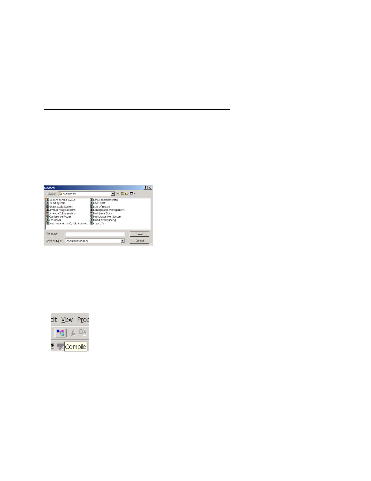
3. Compile Layout
Compile will display number and type of Audia devices required as well as DSP power used.
If compilation cannot find a solution, user intervention may be necessary. Check
for feedback loops, appropriate I/O, appropriate number of units, appropriate
number of CobraNet bundles.
4. Power up Audia devices
Connect supplied power cord to a grounded AC mains voltage of 100-240VAC @50/60Hz.
Connect other end of power cord to power entrance located on the rear of Audia unit. Note status
of front panel LED’s. Under normal conditions, all LED’s will remain green once power-up
sequence has completed.
Page 4
5. Assign IP address to PC
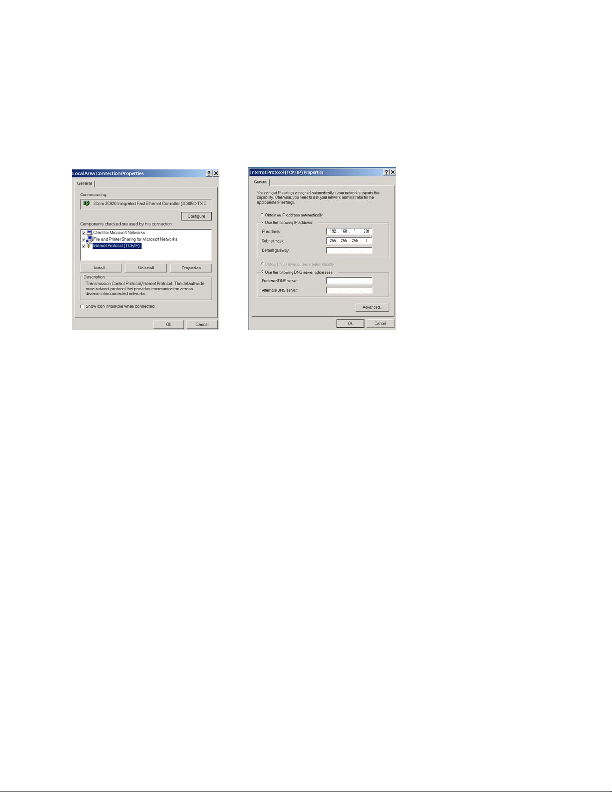
PC must have a unique IP address before it can communicate with an Audia device.
Right Click My Network>Properties>Local Area Connection>Right Click
Properties>TCP/IP>Properties
IP address should be 192.168.1.x (x=1-254)
Subnet mask should be 255.255.255.0
Click Ok when complete
Close My Network
6. Connect PC to network
Attach a “straight-through” Ethernet cable from PC 10/100baseT network card to a 10/100baseT
Ethernet switch. “Straight-through” Ethernet cables connect transmit pins directly to receive pins
(pin 1 to pin 1, pin 2 to pin2, pin 3 to pin3, etc.). You can easily determine if an Ethernet cable is
“straight-through” by looking at the conductors on the RJ-45 connectors. If the wiring is
identical on both ends, it is a “straight through”
Ethernet cable.
7. Connect Audia device to network
Connect one Audia device to network using “straight through” Ethernet cable attached from the
rear panel Ethernet jack to the 10/100baseT Ethernet switch.
Page 5
8. Connect to network with Audia software
Open Audia software then connect to network.
File>Network>Connect to network
Close when complete
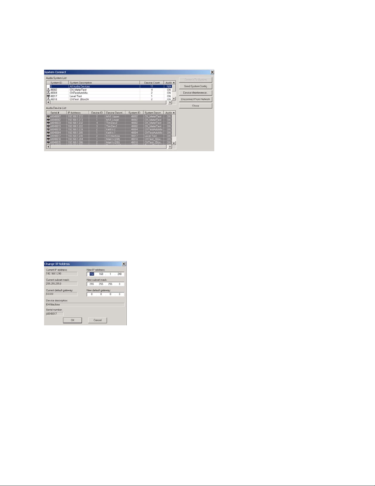
9. Assign IP address to Audia device
All Audia units ship from the factory with an assigned IP address of 192.168.1.101. When using
more than one device in a system, each device must have a unique IP address. Audia device IP
addresses must be different from any PC IP address that will be used in this system.
File>Network>Perform Audia Device Maintenance>Select desired Audia device>Set IP address
IP address should be 192.168.1.x (x=1-254)
Subnet mask should be 255.255.255.0
Default gateway should be 0.0.0.0
Click Ok when complete
Close Device Maintenance when complete
Note: To avoid conflict issues that occur when connecting multiple Audia devices with the same
IP number, be sure to only connect one Audia device at a time to the Ethernet switch when
assigning IP addresses.
10. Repeat steps 6-8 until all Audia devices in system have been connected to network
and assigned a unique IP address.
Page 6
11. Connect CobraNet
For multi-unit systems, “straight-through” Ethernet cables must be connected from the
rear panel CobraNet jack of each unit to a 10/100baseT Ethernet switch.
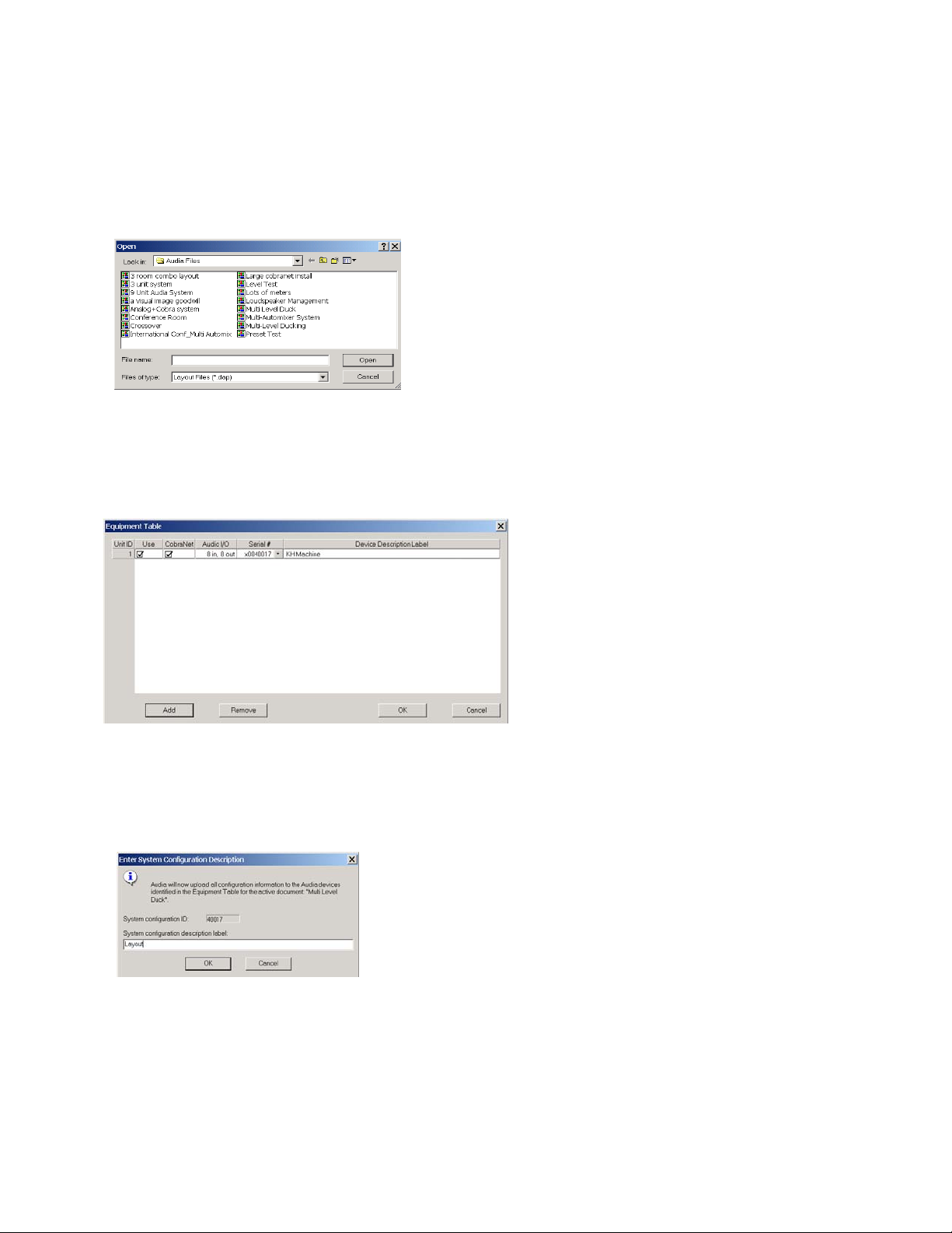
12. Open layout (.dap) file
File>Open>Select file
13. Enter appropriate Audia unit serial numbers to equipment table
Tools>Equipment table>Select desired Audia unit(s)
Select OK when complete
14. Send Configuration
File>Network>Send System Configuration
Sends layout configuration to selected Audia unit(s).
Page 7

15. Start Audio
16. Adjust component parameters as needed
Optional:
17. Disconnect PC from Audia system
File>Network>Disconnect from Audia system
18. Disconnect PC from Network
File>Network>Disconnect from network
Page 8

Connecting to stand alone unit using Audia without CobraNet (AudiaSOLO)
1. Install Audia software on a Windows
®
2000/XP Professional PC
PC must have a 10/100baseT NIC.
2. Design and Layout system
Launch Audia software. Layout signal flow and DSP as desired. Save layout file (.dap).
3. Compile Layout
Compile will display type of Audia device required as well as DSP power used.
If compilation cannot find a solution, user intervention may be necessary. Check
for feedback loops, appropriate I/O, appropriate number of units (only 1 unit possible in
stand alone system).
4. Power up
Connect supplied power cord to a grounded AC mains voltage of 100-240VAC @50/60Hz.
Connect other end of power cord to power entrance located on the rear of Audia unit. Note status
of front panel LED’s. Under normal conditions, all LED’s will remain green once power-up
sequence has completed.
Page 9

5. Assign IP address to PC
PC must have a unique IP address before it can communicate with an Audia device.
Right Click My Network>Properties>Local Area Connection>Right Click
Properties>TCP/IP>Properties
IP address should be 192.168.1.x (x=1-254)
Subnet mask should be 255.255.255.0
Click Ok when complete
Close My Network
6. Connect PC to Audia unit
Connect “cross-over” Ethernet cable (supplied with unit) from PC 10/100baseT
Ethernet card to Ethernet jack located on rear panel of Audia unit. “Cross-over” Ethernet
cables have their pins swapped (pin 1 to pin 3, pin 2 to pin 6, pin3 to pin1) and can
easily be identified by looking at the conductors on the RJ-45 connectors. If the wiring is
different at each end, it is a “cross-over” cable.
7. Connect to Audia unit with Audia software
Open Audia software then connect to unit.
File>Network>Connect to network
Close when complete
Page 10

8. Open layout (.dap) file
File>Open>Select file
9. Enter appropriate Audia unit serial to equipment table
Tools>Equipment table>Select desired Audia unit
Select OK when complete
10. Send Configuration
File>Network>Send System Configuration
Sends layout configuration to selected Audia unit.
Page 11

11. Start Audio
12. Adjust component parameters as needed
Optional:
13. Disconnect PC from Audia system
File>Network>Disconnect from Audia system
14. Disconnect PC from Network
File>Network>Disconnect from network
Page 12

WARRANTY
BIAMP SYSTEMS IS PLEASED TO EXTEND THE FOLLOWING 5-YEAR LIMITED WARRANTY TO THE ORIGINAL
PURCHASER OF THE PROFESSIONAL SOUND EQUIPMENT DESCRIBED IN THIS MANUAL
1. BIAMP Systems warrants to the original purchaser of new products that the product will be free from
defects in material and workmanship for a period of 5 YEARS from the date of purchase from an
authorized BIAMP Systems dealer, subject to the terms and conditions set forth below.
2. If you notify BIAMP during the warranty period that a BIAMP Systems product fails to comply with the
warranty, BIAMP Systems will repair or replace, at BIAMP Systems' option, the nonconforming product.
As a condition to receiving the benefits of this warranty, you must provide BIAMP Systems with
documentation that establishes that you were the original purchaser of the products. Such evidence may
consist of your sales receipt from an authorized BIAMP Systems dealer. Transportation and insurance
charges to and from the BIAMP Systems factory for warranty service shall be your responsibility.
3. This warranty will be VOID if the serial number has been removed or defaced; or if the product has been
altered, subjected to damage, abuse or rental usage, repaired by any person not authorized by BIAMP
Systems to make repairs; or installed in any manner that does not comply with BIAMP Systems'
recommendations.
4. Electro-mechanical fans, electrolytic capacitors, gooseneck microphones, cords connecting handheld
microphones, hard-drives, displays, and normal wear and tear of items such as paint, knobs, handles,
keypads and covers are not covered under this warranty. All server-based devices are warranted for 3
years only.
5. This warranty is in lieu of all other warranties, expressed or implied. BIAMP Systems disclaims all other
warranties, expressed or implied, including, but not limited to, implied warranties of merchantability and
fitness for a particular purpose.
6. The remedies set forth herein shall be the purchaser's sole and exclusive remedies with respect to any
defective product.
7. No agent, employee, distributor or dealer of BIAMP Systems is authorized to modify this warranty or to
make additional warranties on behalf of BIAMP Systems. Statements, representations or warranties made
by any dealer do not constitute warranties by BIAMP Systems. BIAMP Systems shall not be responsible or
liable for any statement, representation or warranty made by any dealer or other person.
8. No action for breach of this warranty may be commenced more than one year after the expiration of this
warranty.
9. BIAMP Systems shall not be liable for special, indirect, incidental, or consequential damages, including lost
profits or loss of use arising out of the purchase, sale, or use of the products, even if BIAMP Systems was
advised of the possibility of such damages.
Biamp Systems
9300 S.W. Gemini Drive
Beaverton, Oregon 97008
(503) 641-7287
Page 13

DoC DSPA201003
EC Declaration of Conformity
Biamp Systems Corporation, as manufacturer having sole responsibility, hereby
declares that the following described product complies with the applicable provisions of
the DIRECTIVES below except as noted herein. Any alterations to the product not
agreed upon and directed by Biamp Systems Corporation will invalidate this declaration.
Product Models: I/O Cards: Controls:
Audia® Series AEC-2HD Logic Box
DSP Platforms: AM-600, -600C RED-1
AudiaFLEX IP-2, OP-2e Remote Control Bus Hub
AudiaFUSION PA-2 Remote Panels; RP-L1, RP-L2, RP-S4
AudiaSOLO TI-2 Select 8, Volume 8, Volume/Select 8
VoIP-2 Voltage Control Box
Product Description: Audio Digital Signal Processors and Control Accessories
Applicable EC Directives: Applicable Harmonized Standards:
LVD Directive (2006/95/EC) Safety EN 60065:2002
EMC Directive (2004/108/EC) Emissions EN 55103-1:1996, Environment E2
Immunity EN 55103-2:1996
R&TTE Directive (1999/5/EC) Terminal Equipment (AudiaFLEX with TI-2 only)
Special Considerations for Product Environment or Compliance:
Shielded cabling must be used for system connections.
RED-1, use only CE marked Power over Ethernet (PoE) device.
Technical Documentation File, Location and Contact
Biamp Systems, Inc. phone: (503) 641.7287
9300 S.W. Gemini Drive fax: (503) 626.0281
Beaverton, OR USA 97008 e-mail: biamp@biamp.com
Authorized Representative: Larry Copley, Compliance Engineer
Authorized Signature:
Issued: March, 2010
:
Page 14

Page 15

Page 16

Page 17

 Loading...