

Page 1

ANC22
Ambient Noise
Compensator
Operation Manual
®
Biamp Systems, 10074 S.W. Arctic Drive, Beaverton, Oregon 97005 U.S.A. (503) 641-7287 http://www.biamp.com
an affiliate of Rauland-Borg Corp.
Page 2

blank
print update
Nov 2/98
Page 3

Ambient Noise Compensator is a stereo controller,
gain to compensate for changes in
TABLE OF CONTENTS
Rear Panel / Connections
Front Panel / Setup
Applications
Options
Specifications / Block Diagram
Warranty
pg. 2
pg. 3
pgs. 4 & 5
pg. 6
pg. 7
ANC22
INTRODUCTION
The ADVANTAGE
which automatically adjusts system
background noise levels. An internal microprocessor senses ambient noise via
a microphone input, compares it to the program signal, and adjusts the
program level accordingly. The ANC22 is ideal for any system troubled by
fluctuating noise levels, such as restaurants, factories, and airports. Setup is
simple and straightforward, and the ANC22 is covered by an ADVANTAGE
Five Year ‘Gold Seal’ Warranty.
ANC22 features include:
♦ balanced stereo program input & output on plug-in barrier
♦ works with balanced or unbalanced, stereo or mono signals
♦ stereo program input selectable for +4dBu or -10dBu levels
♦ balanced/unbalanced noise-sensing input on plug-in barrier
®
ANC22
®
♦ noise-sensing input includes +24V phantom power switch
♦ noise-sensing input with 30dB pad accepts mic or line level
♦ noise-sensing via single mic or multiple mics (external mixer)
♦ adjustable minimum & maximum program level settings
♦ adjustable sample time & program-to-noise gain ratio
♦ automated setup including options to prevent tampering
♦ bypass switch defeats gain adjustments (sets to minimum)
♦ incorporates AES recommended grounding practices
♦
marked and UL / C-UL listed power source
♦ covered by Five-Year “Gold Seal” Warranty
1
Page 4
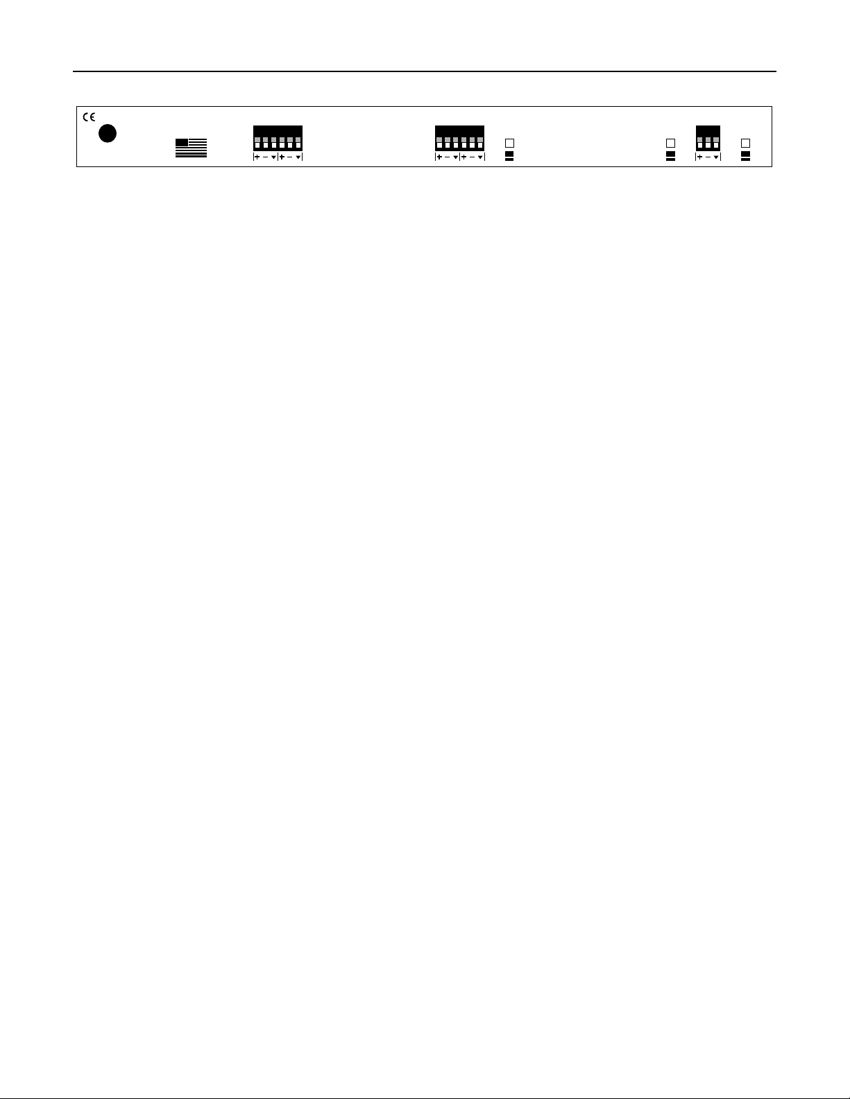
REAR PANEL / CONNECTIONS
BIAMP SYSTEMS
Portland, Oregon
an affiliate of
27V
~
50/60 Hz
10 watts
class 2 wiring
Rauland-Borg Corp.
MADE IN U.S.A.
Output: These plug-in barrier strip terminals are for connection to
the input of a sound system equalizer/amplifier. The Output
provides a balanced stereo line-level program signal, with
automatic level adjustment to compensate for changes in ambient
noise. The ANC22 works equally well with a mono program signal
connected to either the left or right Input/Output. For connection to
unbalanced equalizer/amplifier inputs, wire high to (+) and ground
ý
to (
), leaving (-) unconnected. The Output has an additional 6dB
of gain when used in a balanced fashion.
Input: These plug-in barrier strip terminals are for connection to
the output of a program signal source. The Input accepts a
balanced stereo line-level program signal. The ANC22 works
equally well with a mono program signal connected to either the
left or right Input/Output. For connection to unbalanced program
signal sources, wire high to (+) and ground to both (-) & (
Input will accept either +4dBu or -10dBu nominal level signals (see
Input Level Switch below).
Input Level Switch: This push-button switch determines the
proper gain at the Input, allowing the ANC22 to accomodate
various program source signals. When depressed, the Input Level
Switch selects -10dBu as the appropriate Input signal level (+10dB
gain). This is good for program sources (such as CD, tape, etc.)
which are typically unbalanced line-level signals. When released,
the Input Level Switch selects +4dBu as the appropriate Input
signal level (-4dB gain). This is good for program sources (such
as mixers, equalizers, etc.) which are typically balanced line-level
signals.
R
output
L
This device complies with Part 15 of the FCC Rules.
Operation is subject to the following two conditions:
(1) This device may not cause harmful interference, and
(2) This device must accept any interference received,
including interference that may cause undesired operation.
ý
). The
input
L
R
input
level
+ 4
-10
sense input
-30dB
pad
out
in
phantom
power
off
on
Sense Input: These plug-in barrier strip terminals are for
connection of an external microphone, which is used to pick up
room ambient (background) noise. An internal microprocessor
then samples the noise, calculates an ‘average’ noise level, and
adjusts the program signal level accordingly. The microphone
should be of the balanced, low-impedance type. Condenser
microphones are recommended (see Phantom Power Switch
below), although dynamic microphones are acceptable. For
applications where ambient noise is evenly distributed throughout
the room, sensing microphones with ‘omnidirectional’ or
‘hemispherical’ pick-up patterns are prefered. For applications
where ambient noise is more localized, ‘unidirectional' pick-up
patterns may be more appropriate. If multiple microphones are
desired (to cover a larger area) an external microphone mixer may
be used (see Pad Switch below). Microphones should be placed
within a room so as to pick up both ambient noise and a moderate
amount of program signal from the sound system.
-30dB Pad Switch: When depressed, this push-button switch
provides 30dB of attenuation, to compensate for different signal
levels at the Sense Input. Depress the Pad Switch when Sense
Input signal levels exceed the normal operating range of the front
panel Sense Level control, or when line-level input from a
microphone mixer is desired.
Phantom Power Switch: When depressed, this push-button
switch provides +24 Volts DC phantom power to the Sense Input,
for powering a condenser type microphone. CAUTION: The
Phantom Power Switch must be released (phantom power off)
when the Sense Input is to be connected to a line-level source,
such as a microphone mixer. Always turn levels down before
switching phantom power.
2
Page 5

FRONT PANEL / SETUP
sense level
+ ++ +
low peak
min
level
max
level
10 sec
1 sec 5 min
sample
Power Switch & On Indicator: This switch turns power on, and is
also used to enter setup (see Setup Button & Indicator below).
Setup Button & Indicator: This momentary push-button &
adjacent indicator are used to enter setup mode. Setup mode is a
simple, automated procedure for setting the controls described
below. When setup is completed, the control settings are stored in
non-volatile memory. To enter setup mode
: While the Power
Switch is turned off, press and hold the Setup Button. While
holding the Setup Button, turn the Power Switch on. Continue
holding the Setup Button until the Setup Indicator lights. When the
Setup Button is released, the Min Indicator will also light (see
Setup / dB Gain Display below). NOTE: Setup requires program
& sense signals be present. Once setup is completed, the Setup
button may be disabled (see Options on pg. 6).
Setup / dB Gain Display: This row of eight indicators serves
three purposes. During setup mode, individual indicators will light
to show the proper sequence of control adjustments. During
normal operation, the display provides gain metering. During
Bypass, the Min Level control setting is displayed (see below).
NOTE: If the Overload indicator flashes during normal operation,
reduce input signal levels and repeat the setup procedure.
Min Level: This screwdriver adjustable control determines the
minimum output gain of the ANC22 (for periods of low ambient
noise). Adjust Min Level during setup mode, only
Indicator is lit. Set the Min Level control for the program volume
which will be appropriate when background noise is the ‘quietest’.
Min Level has a range of -20dB to +18dB. Once Min Level has
been set, press the Setup Button and the Sense Indicator will light
(see Sense Level & Indicators below).
Sense Level & Indicators: This screwdriver adjustable control
determines the appropriate sense input level. Initially, this control
should be increased only until the Low Indicator goes off. Once
Sense Level has been set, press the Setup Button and the Max
Indicator will light (see Max Level below). NOTE: Max Level
settings may cause the Peak Indicator to light. If so, decrease
Sense Level until the Peak Indicator goes off, then repeat the
setup procedure to store the new settings in non-volatile memory.
Once setup is completed, do not disturb the Sense Level control.
Max Level: This screwdriver adjustable control determines the
maximum output gain of the ANC22 (for periods of high ambient
noise). Adjust Max Level during Setup Mode, while the Max
Indicator is lit. Set the Max Level control for the program volume
which will be appropriate when backgound noise is the ‘loudest’.
Max Level has a range from the Min Level setting to +18dB. Once
Max Level has been set, press the Setup Button and the Time
Indicator will light (see Sample Time below). NOTE: If Max Level
1:1
30 sec
2.5 min
2:1
1:2
gain
time
ratio
while the Min
ADVANTAGE ANC22
rate
Ambient Noise Compensator
bypasssetup
on
o
sense min max time ratio overload
setup
6391812 24 32 40
dB gain
settings cause the Peak Indicator to light, decrease Sense Level
until the Peak Indicator goes off, then repeat the setup procedure
to store the new settings in non-volatile memory
Sample Time: This screwdriver adjustable control determines the
length of time the ANC22 uses to sample noise levels at the Sense
Input. Sample Time affects how accurately the ANC22 will
calculate an ‘average’ noise level, as well as how quickly it will
respond with a program volume adjustment. Lower settings allow
less sampling time, but offer a quicker response time. This is good
for applications (such as subway terminals) where the ambient
noise level may change drastically within a short period of time.
Higher settings provide a longer sampling time, and a longer
response time. This is good for applications (such as restaurants)
where the ambient noise level changes gradually. A setting of ‘10
sec’ is a good starting point for most applications. Once Sample
Time has been set, press the Setup Button and the Ratio Indicator
will light (see Gain Ratio below). NOTE: During setup of Sample
Time, the Bypass Indicator functions as a Rate Indicator, and will
flash each time a complete sampling period has elapsed (see
Bypass Switch & Indicator below).
Gain Ratio: This screwdriver adjustable control determines how
much the ANC22 will increase program volume, relative to a given
increase in ambient noise. A minimum setting (‘1:2’) produces a
1dB increase in program volume for every 2dB increase in
‘average’ ambient noise level. This is good for applications (such
as background music) where the program signals must remain
subdued. A maximum setting (‘2:1’) produces a 2dB increase in
program volume for every 1dB increase in ‘average’ ambient noise
level. This is good for applications (such as foreground audio)
where program signals must remain intelligible. Gain Ratio
settings are also affected by ‘sense’ microphone placement. A
setting of ‘1:1’ is a good starting point for most applications. Once
Gain Ratio has been set, press the Setup Button. The Gain Ratio
Indicator will go off, the control settings will be stored in nonvolatile memory, and the ANC22 will enter the normal operating
mode. NOTE: Once setup is completed, the Setup Button may be
disabled. Max Level, Sample Time, & Gain Ratio controls may be
enabled to allow adjustments during normal operation. These
adjustments will not be stored in non-volatile memory without
repeating the setup procedure (see Options on pg. 6).
Bypass Switch & Indicator: When pressed in, this switch will
defeat any ANC22 program gain increases, and set the program
volume to minimum (as determined by the Min Level control). The
adjacent indicator will light whenever Bypass is enabled. NOTE:
During normal operation, this indicator functions as a Rate
Indicator for each sampling period (if Bypass is not enabled).
3
Page 6

APPLICATIONS
Bar with Stereo Sound System
ANC22
27V
~
50/60 Hz
10 watts
class 2 wiring
mEQ152
27V
~
50/60 Hz
15 watts
class 2 wiring
162738495
BIAMP SYSTEMS
Portland, Oregon
an affiliate of
Rauland-Borg Corp.
MADE IN U.S.A.
10
5 Rock
L
R
BIAMP SYSTEMS
PORTLAND,OREGON
an affiliate of
Rauland-Borg Corp
MADE IN U.S.A.
This device complies with Part 15 of the FCC Rules.
Operation is subject to the following two conditions:
(1) This device may not cause harmful interference, and
(2) This device must accept any interference received,
including interference that may cause undesired operation.
music
service
inputoutput
L
R
output
input
channel 2 channel 1
input
level
+ 4
-10
ambient noise
sensing mic
sense input
-30dB
pad
out
in
output
input
phantom
power
off
on
CPA130
USE ONLY WITH
250V FUSE
110V
level 2
115V: 3A SB
230V: 1.5A SB
115/230 VAC
50/60 Hz
300 Watts max
input 2 input 1
gnd---+ + gnd---
output 2
--- + + ---
output 1
stereo speaker system
level 1
stereo
mono bridge
ADVANTAGE
CPA 130
MADE IN U.S.A.
4
Page 7

APPLICATIONS
Airport with Music & Page System
301
27V
~
50/60 Hz
DC out
15 watts
class 2 wiring
±12VDC
MSP11
27V
~
50/60 Hz
12 watts
class 2 wiring
ANC22
27V
~
50/60 Hz
10 watts
class 2 wiring
BIAMP SYSTEMS
main out
stack in
MADE IN U.S.A.
serial port
link port logic inputslink
an affiliate of Rauland Borg Corp.
patch
in out
remote
vc
patch
enable
music
service
301
input
ch 3 duck
phntm
remote
ch 2
ch 1
3
BIAMP SYSTEMS
Portland, Oregon
an affiliate of
Rauland-Borg Corp.
MADE IN U.S.A.
message
repeater
output
input
pad
phntm
2
input
pad
paging
source
input
phntm
1
pad
BIAMP SYSTEMS
Portland, Oregon
an affiliate of
Rauland-Borg Corp.
MSP11
MADE IN U.S.A.
concourse ambient noise sensing mics
R
output
L
This device complies with Part 15 of the FCC Rules.
Operation is subject to the following two conditions:
(1) This device may not cause harmful interference, and
(2) This device must accept any interference received,
including interference that may cause undesired operation.
301
27V
50/60 Hz
15 watts
class 2 wiring
gate 1
BIAMP SYSTEMS
an affiliate of Rauland Borg Corp.
~
main out
stack in
DC out
±12VDC
MADE IN U.S.A.
input
L
R
301
patch
remote
in out
vc
input
level
input
ch 3 duck
pad
phntm
remote
patch
enable
ch 2
ch 1
3
+ 4
-10
gate 2
input
phntm
2
gate 3
-30dB
pad
input
phntm
1
sense input
pad
phantom
power
off
on
pad
out
in
CPA650
level 2 level 1
Ω
4 operation: use 5A NB
Ω
8 operation: use 3A NB
F
E
U
S
S
U
E
F
speaker fuse 2 speaker fuse 1
CAUTION:
To reduce the risk of fire, replace
only with same type 8A SB fuse.
F
E
U
S
S
U
E
F
AC Fuse
120 VAC
E17934
50/60 Hz 1000 Watts max
input 2
325W/4Ω 325W/4Ω
output 2 output 1
class 2 wiring acceptable
input 1
gnd---+ + gnd---
++--- ---
ground
normal lift
LISTED 989M
COMMERCIAL
U
.
L
AUDIO EQUIP.
Ω
4 operation: use 5A NB
Ω
8 operation: use 3A NB
stereo
5
ADVANTAGE
F
E
U
S
S
U
E
F
mono bridge
CPA 650
distributed speaker system
MADE IN U.S.A.
Page 8

OPTIONS
To access internal options
and the top panel facing up. Remove the top panel (two screws on each side; three screws along top edge of both front and rear panels).
Disable Front Panel Setup Button: Once setup mode is completed and control settings are stored in non-volatile memory, the front
panel Setup Button may be disabled to prevent further adjustments or tampering. To disable the Setup Button
switch on the circuit board (see diagram below). Using a screwdriver or other implement, Move the ‘opt.1’ DIP switch to the left (be careful
not to disturb the other DIP switch settings). Replace the top panel. The Setup Button may again be enabled by reversing this process.
NOTE: Max Level, Sample Time, & Gain Ratio are disabled during normal
Enable Front Panel Controls: Once setup mode is completed and control settings are stored in non-volatile memory, the Max Level,
Sample Time, & Gain Ratio front panel controls are disabled to prevent further adjustments or tampering. However, these controls may be
enabled to allow adjustments during normal operation. Adjustments made during normal operation will not be stored in non-volatile
memory without repeating the setup procedure. To enable the Front Panel Controls
(see diagram below). Using a screwdriver or other implement, Move the ‘opt.2’ DIP switch to the right (be careful not to disturb the other
DIP switch settings). Replace the top panel. The controls may again be disabled by reversing this process. NOTE: The Sense Level
control cannot
be disabled. Once setup is completed, do not disturb the Sense Level control.
opt.4
opt.3
opt.2
opt.1
: First, disconnect power from the unit. Then, lay the unit on a flat surface with the front panel facing forward
: Locate the 4-gang DIP
operation (see below).
: Locate the 4-gang DIP switch on the circuit board
circuit
board
DIP
switch
options
front panel
power
switch
6
Page 9

SPECIFICATIONS / BLOCK DIAGRAM
_______________________________
Frequency Response (20Hz~20kHz @ +4dBu):
Total Harmonic Distortion (20Hz~20kHz @ +4dBu):
Output Noise (20Hz~20kHz @ unity gain):
+4dBu input reference
-10dBu input reference
Signal-to-Noise Ratio (20Hz~20kHz @ unity gain):
+4dBu input reference
-10dBu input reference
Maximum Gain:
+4dBu input reference
-10dBu input reference
Gain Range (40dB):
+4dBu input reference
-10dBu input reference
Response Time (variable):
Gain Ratio (variable) (∆ gain dB / ∆ noise dB):
Sense Input Impedance (balanced):
Sense Input Maximum Level (pad in):
Sense Input Maximum Gain:
-20dB ~ +20dB
-6dB ~ +34dB
SPECIFICATIONS
+0/-0.2dB
< 0.1%
< -72dBu
< -75dBu
76dB
70dB
+20dB
+34dB
1 sec ~ 5 min
½ ~ 2
2k ohms
+18dBu
60dB
Stereo Input Impe dance:
balanced
unbalanced
Stereo Input Maximum Level:
+4dBu input reference
-10dBu input reference
Stereo Output Impedance:
balanced
unbalanced
Stereo Output Maximum Level:
balanced
unbalanced
Power Consumption:
Connectors:
Dimensions:
height
width
depth
Weight:
______________________________
39k ohms
19k ohms
+21dBu
+9dBu
100 ohms
50 ohms
+24dBu
+18dBu
< 10 watts
plug-in barrier
1.75” (44mm)
19” (483mm)
7.25” (184mm)
5.5 lbs. (2.5kg)
Left
Input
Right
Input
Sense
Input
+24V
phntm
power
min. level
max. level
sample time
-10
+4
30dB
pad
ANC22 Block Diagram
level
detect
peak
level
detect
sense
level
setup
bypass
VCA
VCA
D-to-A
conversion
and
central
microprocessor
Left
Output
Right
Output
EEPROM
LED
status
indicators
and
level
meter
gain ratio
7
Page 10

WARRANTY
BIAMP SYSTEMS IS PLEASED TO EXTEND THE FOLLOWING 5-YEAR
LIMITED W A RRANTY TO THE ORIGINAL PURCHASER OF THE
PROFESSIONAL SOUND EQUIPMENT DESCRIBED IN THIS MANUAL.
BIAMP Systems expressly warrants this product to be
free from defects in material and workmanship for a
period of 5 YEARS from the date of purchase as a
new product from an authorized BIAMP Systems
dealer under the following conditions.
1. In the event the warranted BIAMP Systems product
requires service during the warranty period, BIAMP
Systems will repair or replace, at its option, defective
materials, provided you have identified yourself as the
original purchaser of the product to any authorized
BIAMP Systems Service Center. Transportation and
insurance charges to and from an authorized Service
Center or the BIAMP Systems factory for warranted
products or components thereof to obtain repairs shall
be the responsibility of the purchaser.
2. This warranty will be VOIDED if the serial number
has been removed or defaced; or if the product has
been subjected to accidental damage, abuse, rental
usage, alterations, or attempted repair by any person
not authorized by BIAMP Systems to make repairs; or
if the product has been installed contrary to BIAMP
Systems’s recommendations.
3. Electro-magnetic fans, electrolytic capacitors, and
the normal wear and tear of appearance items such
as paint, knobs, handles, and covers is not covered
under this warranty.
4. BIAMP SYSTEMS SHALL NOT IN ANY EVENT BE
LIABLE FOR SPECIAL, INCIDENTAL, OR
CONSEQUENTIAL DAMAGES, INCLUDING LOST
PROFITS, LOSS OF USE, PROPERT Y DAMAGE, INJURY
TO GOODWILL, OR OTHER ECONOMIC LOSS OF ANY
SORT. EXCEPT AS EXPRESSLY PROVIDED HEREIN,
BIAMP SYSTEMS DISCLAIMS ALL OT HER LIABILITY TO
PURCHASER OR ANY OTHER PERSONS ARISING OUT
OF USE OR PERFORMANCE OF THE PRODUCT,
INCLUDING LIABILITY FOR NEGLIGENCE OR STRICT
LIABILITY IN TORT.
5. THIS WARRANTY IS IN LIEU OF ALL OTHER
WARRANTIES EXPRESSED OR IMPLIED. BIAMP
SYSTEMS EXPRESSLY DISCLAIMS ALL IMPLIED
WARRANTIES OF MERCHANTABILITY AND FITNESS
FOR A PARTICULAR PURPOSE. THE REMEDIES SET
FORTH HEREIN SHALL BE THE PURCHASER’S SOLE
AND EXCLUSIVE REMEDIES WITH RESPECT TO ANY
DEFECTIVE PRODUCT. THE AGENTS, EMPLOYEES,
DISTRIBUTORS, AND DEALERS OF BIAMP SYSTEMS
ARE NOT AUTHORIZED TO MODIF Y THIS WARRANTY
OR TO MAKE ADDITIONAL WARRANTIES BINDING ON
BIAMP SYSTEMS. ACCORDINGLY, ADDITIONAL
STATEMENTS SUCH AS DEALER ADVERTISEMENTS
OR REPRESENTATIONS DO NOT CONSTITUTE
WARRANTIES BY BIAMP SYSTEMS.
6. No action for breach of this warranty may be
commenced more than one year after the expiration of this
warranty.
Thank you for purchasing BIAMP SYSTEMS...
AMERICAN SOUND CRAFTSMANSHIP
Biamp Systems
10074 S.W. Arctic Drive
Beaverton, Oregon 97005 U.S.A.
(503) 641-7287
http://www.biamp.com
585.0127.00
Page 11

Page 12

Page 13

Page 14

 Loading...