

Page 1

AMP-450P Amplifier
OPERATION MANUAL
SEPTEMBER 2018
Page 2

AMP-450P PRODUCT DESCRIPTION
The AMP-450P is a four-channel AVB PoE+ amplifier for use in Tesira® systems. The output channels are software
configurable including selectable power versu s channel count. PoE+ power allows the AMP-450P to be placed wherever
you need it. Suitable for air-handling spaces, t he am plifier can be located close to ceiling speakers if desired. The AMP450P includes an internal limiter and can provide 3W RMS of continuous power to all four channels. The Tesira AMP450P is also capable of operating in a “burst” mode to support higher power levels for dynamic content for brief period s.
The amplifier serves as a dedicated endpoint in a T esira system, making installations easier to design, support and
maintain. The AMP-450P is ideal for Tesira-equipped conference rooms and other applications.
Page 3
AMP-450P SETUP AND USE
Setup and Use
The Tesira software provides an intuitive interf ace f or setup and programming of the AMP-450P. The information supplied
by this manual relates to physical connections and device setup. For more details on software setup, please consult the
Tesira Help File. For device specifications please consult the AMP-450P Datasheet.
The Tesira AMP-450P does not connect to Telecom Network V oltage (TNV) circuitry and is considered a Network
Environment Zero device.
Page 4

Front Panel and Connectors
Status
LED Indicator
No power
Off
Powered but not ready to receiv e configuration
Red Solid
Ready to receive configurati on or updating firmware
Yellow Solid
Configured and ready to parti c ipate in the system
Green Solid
Amplifier is in Locate mode (triggered from the software)
Green Flashing
Unit has Major Alarm condition
Red Flashing
Unit has Minor Alarm condition
Yellow Flashing
Unit has both a Major and Minor Al arm condition
Red & Yellow Flashing
Status
LED Indicator
No power
Off
Clip detected
Red Solid
Amplifier limiter engaged
Yellow Solid
Powered
Green Solid
Amplifier is in Locate mode (tr iggered from the software)
Green Flashing
Amplifier has failed to initialize, an error is present, or the
amp is temporarily muted due to an a udio burst
PoE+ power is not available or insufficient to power the
amplifier so it has been turned off
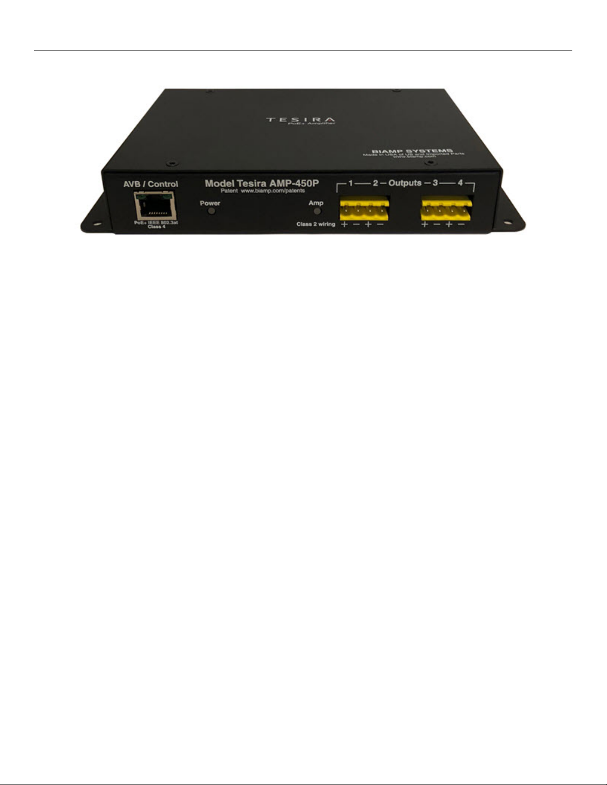
AMP-450P FRONT PANEL
Figure 1 AMP-450P Front Panel
AVB / Control
1.
Facilitates connection to the Tesira AVB network for audio and control. This RJ-45 port may either be connected
directly to the Tesira AVB port (via a PoE+ injector) for a single device system or via a PoE+ network swit c h in a
multi-device AVB system. IEEE 802.3at Power ov er Ethernet Plus (PoE+) Class 4 is required as there are no
other provisions for power inlet.
Power/System Status
2.
A multi-color LED provides information about the status of the device.
Amp Status
3.
A multi-color LED provides information about the status of the amplifier.
Output 1 - 4
4.
4 x 3W RMS or 2 x 7W RMS or 1 x 15W RMS output at low impedance 4Ω / 8Ω.
Red Flashing
Red & Yellow Flashing
Page 5

Channel
Output
1
15W
2
Not Used
3
Not Used
4
Not Used
Channel
Output
1
7W
2
7W
3
Not Used
4
Not Used
Channel
Output
1
3W
2
3W 3 3W
4
3W
AMP-450P WIRING TOPOLOGIES
Amplifier Output and Wiring
The amplifier can be configured in either single channel, two-channel or four-channel mode in the Tesira soft ware. Any
unconfigured channels will not pass audio ev en i f speakers are connected.
1 x 15W RMS
2 x 7W RMS
4 x 3W RMS
Figure 2 Amplifier Speaker Wiring 1 x 15W RMS
Figure 3 Amplifier Speaker Wiring 2 x 7W RMS
Figure 4 Amplifier Speaker Wiring 4 x 3W RMS
Page 6

AMP-450P INSTALLATION
Mounting & Installation
Flanges on each side of the unit have mounting holes to secure the AMP-450P with hardware (not provided) if desired. An
optional seismic cable may be installed through t he center hole on the left mounting flange in lieu of hardware mounting.
Newer versions of the AMP-450P (Sept 2018 or later) come equipped with clips that can sec ure t he A M P-450P above a
ceiling tile to the ceiling “T-bars.”
General Mounting and Installation Notes
• 330 feet (100 meters) maximum from the Ethernet switch to the AMP-450P
• Flange pre-drilled for seismic cable install at i on
• Includes ceiling T-bar mounting clips (x2)
Seismic Cable Installation (optional)
To install the optional seismic cable, place the unit in the desired location:
1. Feed the seismic cable through the hole in AMP-450P mounting flange.
Figure 5 AMP-450P Seismic Cable Mounti ng
2. Feed the cable through one end of the locking mechanism.
NOTE: The ends indicated by the blue arrow need to be depressed to allow the cable to pass through. Internal
guides ensure the cable will be routed through the co rrect path.
3. Attach the loop to a secure location and apply sufficient tension for minimal slack.
Page 7

4. Make sure the ends of the lock mechanism are in the loc ked position (out) as indicated by the blue arrows.
Figure 6 Lock Mechanism Orientation
T-Bar Clip Installation
If using clips to install the AMP-450P above a ceiling tile, do the steps that follow:
1. Remove ceiling tiles adjacent to the mounting locat i on as required for access.
2. Install the clips onto the notched fittings on top of the AMP-450P.
3. Fit the clips over two perpendicular T-bars (in the corner) above the ceiling tile with the AMP-450P oriented as
required.
NOTE: If installing a TB-1 tile bridge (typically installed to accommodate TCM or DCM model plenums and
microphones) the AMP-450P may be mounted to any edge of the ceiling T-bar and the TB-1. See the TB-1 and/or
TCM-1 installation manuals for more information at https://www.biamp.com/downloads
.
Figure 7 AMP-450P Mounting Clip Installation
Visit www.biamp.com to obtain firmware and software updates related to this product. To speak with an Applications Engineer, please call
1.503.641.7287 or email support@biamp.com
.
Page 8

FCC NOTICE
FCC Part 15 –
This device complies with part 15 of the FCC Rules. Operation is subject to the following two conditions: (1) this
device may not cause harmful interference and (2) this device must accept any interference received, including
interference that may cause undesired operation.
 Loading...