

Page 1

Operation Manual
(printable Help file)
Page 2

Table of Contents
Architect's & Engineer's Specification ............................................................................................................................... 2
Documentation...................................................................................................................................................................
3
1. .............................................................................................................................................................
Surface ..............................................................................................................................................................................
Property Sheet...................................................................................................................................................................
Control Library...................................................................................................................................................................
Menus................................................................................................................................................................................
File Menu .......................................................................................................................................................................
Edit Menu.....................................................................................................................................................................
View Menu ...................................................................................................................................................................
Control Library Menu ...................................................................................................................................................
Tools Menus ................................................................................................................................................................
Layout Menu ................................................................................................................................................................
Windows Menu ............................................................................................................................................................
Help Menu ...................................................................................................................................................................
Toolbars...........................................................................................................................................................................
Standard Toolbar .........................................................................................................................................................
Object Bar....................................................................................................................................................................
Control Bar...................................................................................................................................................................
Layout Bar ...................................................................................................................................................................
Format Bar...................................................................................................................................................................
Network Bar .................................................................................................................................................................
Status Bar ....................................................................................................................................................................
Keyboard Shortcuts.........................................................................................................................................................
Keyboard Shortcuts .....................................................................................................................................................
2. .....................................................................................................................................
Placing Objects................................................................................................................................................................
Customizing Appearance ................................................................................................................................................
Adding Control Pages......................................................................................................................................................
Application Controls.........................................................................................................................................................
Adding Popup Controls....................................................................................................................................................
Testing Control Surfaces.................................................................................................................................................
4 Software Tools
4
5
7
8
9
11
12
16
17
29
44
46
47
48
49
50
67
68
69
70
71
71
73 Designing Control Surfaces
73
75
76
77
78
79
3. .........................................................................................................................................
Network Considerations...................................................................................................................................................
Accessing Control Surfaces ............................................................................................................................................
Preparing Control Surfaces .............................................................................................................................................
4. .............................................................................................................................................
Using Control Surfaces....................................................................................................................................................
5. ...........................................................................................................................................................................
80 Sending Control Surfaces
80
81
82
83 Using Control Surfaces
83
85 Index
ii
Page 3

Introduction
What is daVinci?
daVinci is a software program designed to allow the creation and use of customized computer
control screens with Audia® and Nexia® digital audio systems. The function and appearance of
the graphic control interface can be tailored to the exact needs of the user. Individual or grouped
sets of controls may be placed and assigned to specific system functions...or...component
objects can be copied directly from the system design file into daVinci software, producing
completely pre-assigned control surfaces. An array of drawing tools is provided for extensive
graphic manipulation of controls, backgrounds, and labeling. Control screens can be created with
the ability to easily navigate between multiple pages of operation. Once created, a control file is
downloaded into the system, where it can then be accessed by multiple network computers
running daVinci software. The software cannot alter the system design itself, and control access
to the system may be password protected. System control may be provided using a combination
of daVinci software, hardware control panels, and third-party RS-232, simultaneously.
1
Page 4

daVinci Printed Doc
Architect's & Engineer's Specification
The control software program shall allow the creation and use of customized computer control
screens with Audia® and Nexia® digital audio systems. The software shall allow function and
appearance of the graphic control interface to be tailored to the exact needs of the user.
Individual or grouped sets of controls may be placed and assigned to specific system fun ctions,
or component objects may be copied directly from the Audia or Nexia system design file into the
control software, resulting in completely pre-assigned control surfaces. An array of drawing tools
shall be provided for extensive graphic manipulation of controls, backgrounds, and labeling.
Control screens may be created with the ability to easily navigate between multiple pages of
operation. Once created, a custom control file may downloaded into the Audia or Nexia system,
where it can then be accessed by multiple network computers which are running the control
software. The control software shall not alter the system design itself, and control access to the
system shall be password protected. System control may be provided using a combination of the
control software, hardware control panels, and third-party RS-232, simultaneously. Minimum
recommended system requirements shall be: Windows® XP Professional/Vista; Pentium® 4-1.5;
256MB RAM; 1280x1024 screen resolution.
The control software program shall be daVinci™.
Windows® is a registered trademark of Microsoft Corporation.
Pentium® is a registered trademark of Intel Corporation.
2
Page 5

Introduction
Documentation
The information contained in this Help file can be printed in manual form (with Table of Contents
and Index). Two PDF files are provided on the software CD for this purpose. The file daVinci.pdf
is intended for printing on Letter (8.5" x 11") size paper. The file daVinci-A4.pdf is intended for
printing on A4 (210mm x 297mm) size paper. These are printable Help files. Similar PDF files are
also available on the software CD-ROM (for Audia/Nexia Help, RS-232 Control, and Quick Start
Guide documents).
3
Page 6
Software Tools
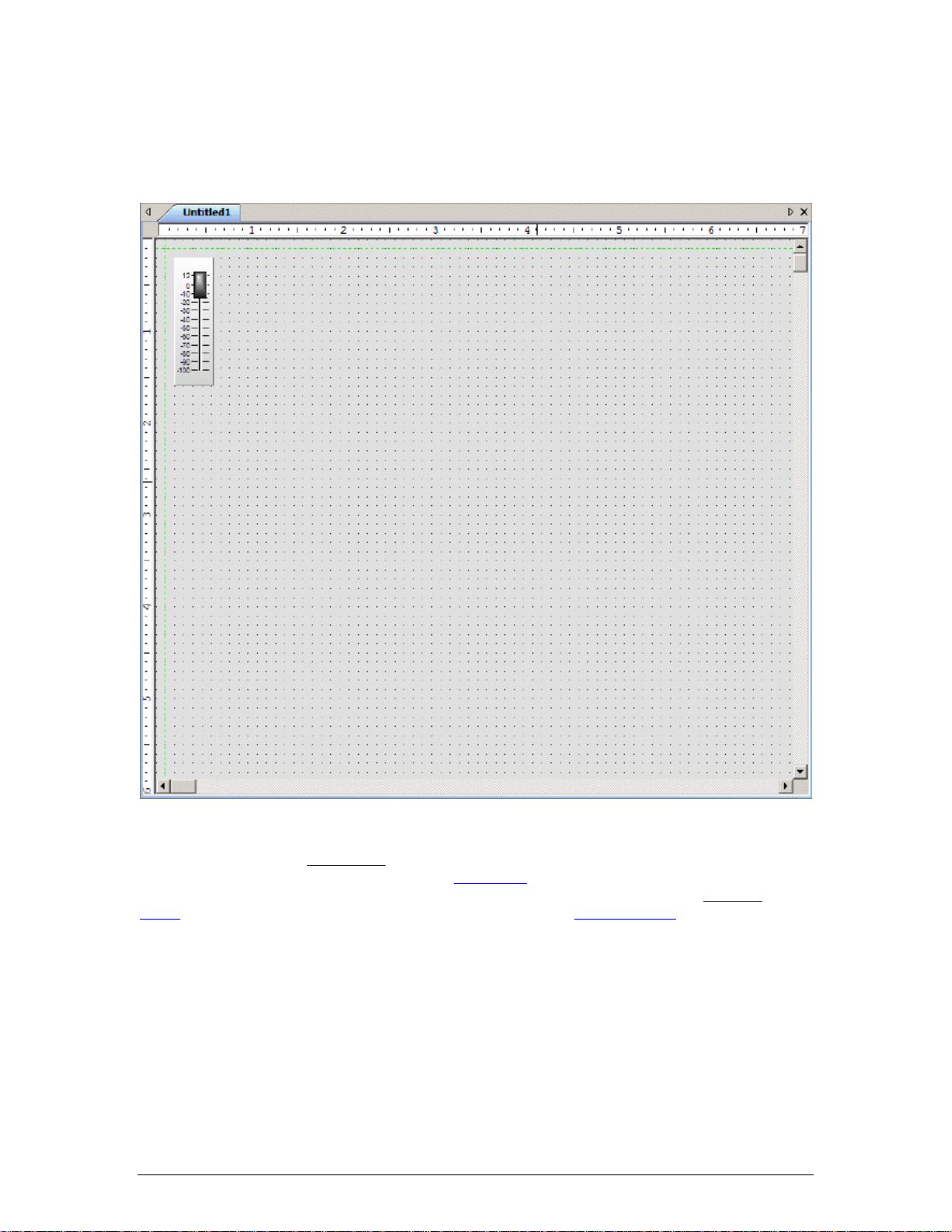
Surface
The Surface is where objects are arranged to create a custom control screen. Individual controls
may be placed from the Control Bar
system components, may be placed from the Object Bar
and assigned to specific component functions within the system design, using the Property
Sheet. Customized or often-used controls can be copied to the Control Library for future
placement into the Surface. However, component objects may instead be copied directly from the
system design file into the Surface, where they will appear as appropriately grouped and
assigned controls.
. Grouped sets of controls, representing typical multi-function
. The controls can then be customized
4
Page 7
Property Sheet
Software Tools
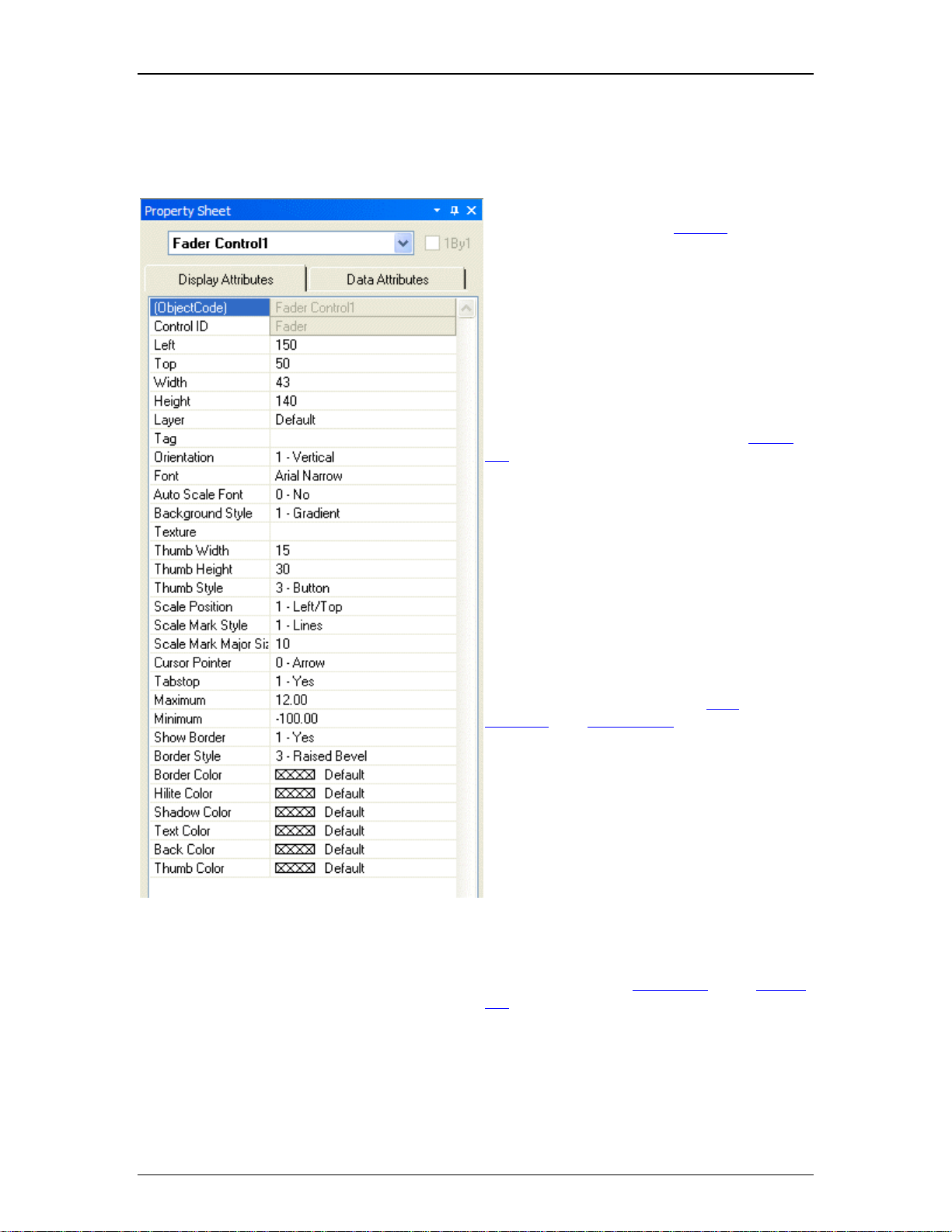
The Property Sheet is where various attributes
of an object selected in the Surface
customized.
may be
Display Attributes affect such things as
position, size, shape, orientation, color, and
labeling.
Data Attributes affect assignment of a control
to a specific component in the system design
file. Instance ID (or Instance ID Tag), DSP
Block Type, Attribute, and Input/Output
information must be available from the system
design file. Grouped controls from the Object
Bar require only an Instance ID (or Instance ID
Tag), which can be assigned to the group as a
whole by first disabling 1By1 (this allows
access to common properties within a ‘MultiSelection’ of controls). An alternative is to copy
components from the system design file
directly into the Surface, where they will
appear as appropriately grouped and assigned
controls. These controls can then receive
further customization of their Display
Attributes.
Data Attributes also include User Access
Level, which can be used to make specific
controls inaccessible for certain User
Accounts, and Gang Group, which allows
multiple controls of the same type to have
combined operation.
Data Attributes are available only for control
type objects. Display Attributes are available
for all objects, including non-control objects
such as text boxes, frames, and the Surface
background.
Certain Display Attributes, such as position,
size, shape, color, and labeling, can be
customized within the Surface itself. Some of
these can be done by simply dragging the
object, others can be done through selections
made from either the Layout Bar
or the Format
Bar.
5
Page 8

daVinci Printed Doc
A Menu icon (upper-right of title-bar) allows the Property Sheet to be docked or floating, and to
be hidden (closed) or to utilize Auto Hide (if docked). The menu may also be accessed by rightclicking over the Property Sheet. The thumb-tack allows the Property Sheet to remain open
(disables Auto Hide). To close the Property Sheet, click on the "X" in the upper right corner. The
Property Sheet may again be opened by selecting it from the Layout Bar
during actual control or test sessions.
. It is not accessible
6
Page 9
Control Library
Software Tools
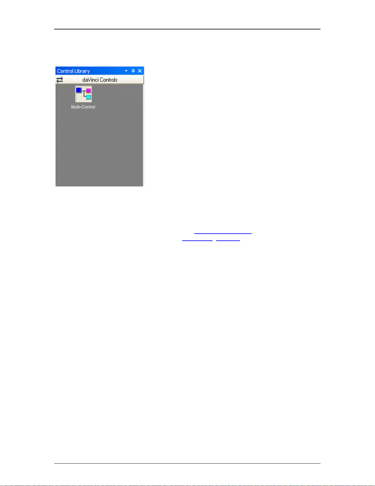
The Control Library provides a convenient location for storing
customized or often-used controls. Simply select an object in
the Surface and copy it into the Control Library (Alt+drag or
right-click copy/paste). An icon for the control appears under the
selected category (default: daVinci Controls). The icon can be
re-named by selecting it, then clicking on the text. New category
files (.apl) may be created by right-clicking over the Control
Library.
When a category is selected, the available components appear
under the category heading. A vertical scroll bar will appear if all
available components in a category cannot be displayed. To
place a control, simply drag the icon into the Surface. When
Control Library changes are made, the affected category files
(.apl) are saved automatically (under Shared Documents).
A Menu icon (upper-right of title-bar) allows the Control Library
to be docked or floating, and to be hidden (closed) or to utilize
Auto Hide (if docked). The menu may also be accessed by
right-clicking over the Control Library. The thumb-tack allows
the Control Library to remain open (disables Auto Hide). To
close the Control Library, click on the "X" in the upper right
corner. The Control Library may again be opened by selecting a
category from the Control Library Menu
accessed via View Menu
actual control or test sessions
>Toolbars. It is not accessible during
. It can also be
7
Page 10

daVinci Printed Doc
Menus
8
Page 11
File Menu
File Menu
Software Tools
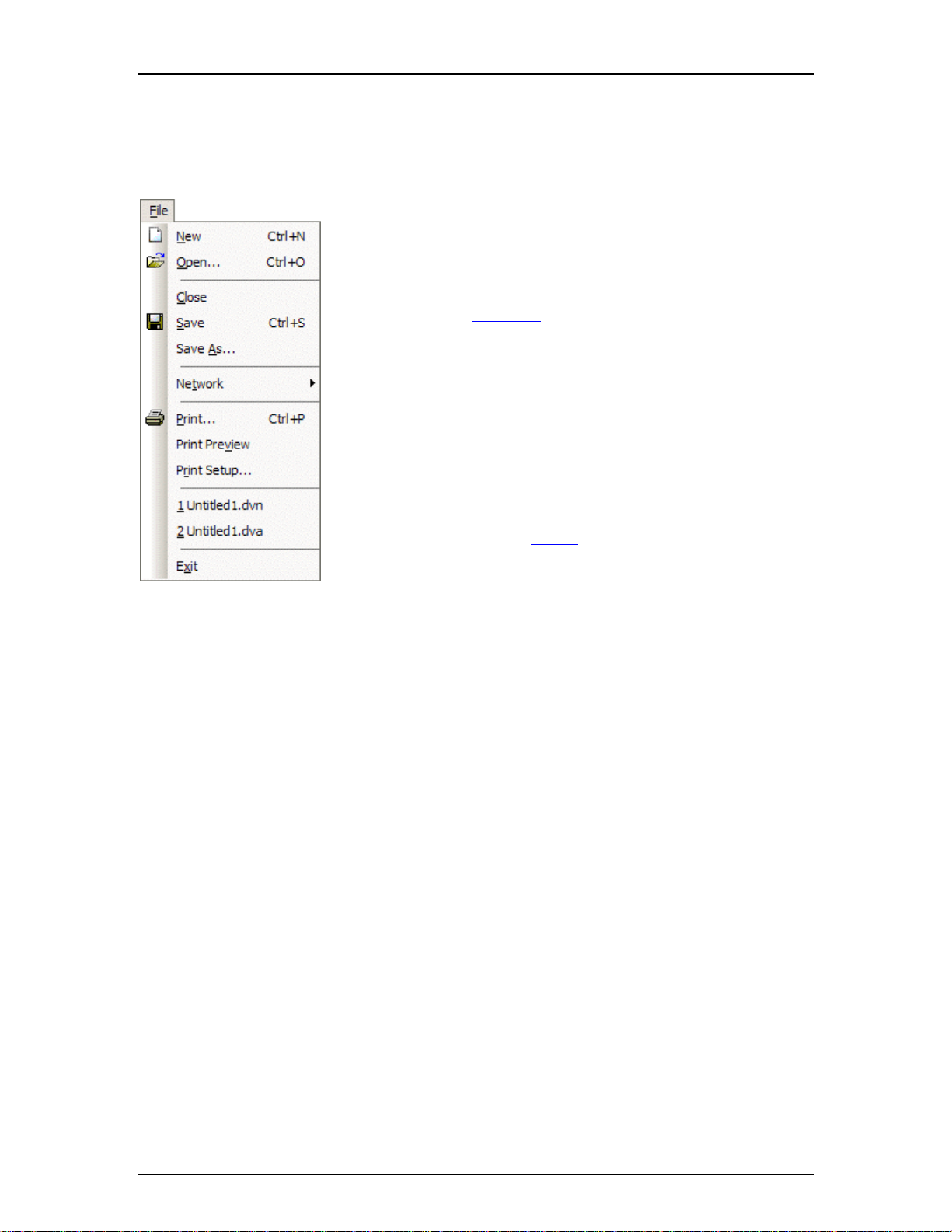
New starts a fresh control file. Open retrieves a previously saved file.
Close shuts the current file, and saves changes. Save stores the
current file under My Documents. Save As stores the current file with
a choice of directory location and file name. NOTE: File extensions
are: .dva for Audia and .dvn for Nexia.
Network provides a sub-menu of related functions.
Print opens a dialog box to adjust printer settings and print the
Surface. Print Preview displays anticipated printing results, based on
Print Setup. Print Setup opens a dialog box to adjust printer settings.
Recently saved files are listed at the bottom of the menu, for easy
access.
Exit closes the daVinci program, with a prompt to save the file if
necessary. If a file is open during Exit, that file will re-open at next
session.
The menu shows associated toolbar icons and keyboard shortcuts.
9
Page 12
daVinci Printed Doc
sub-menus
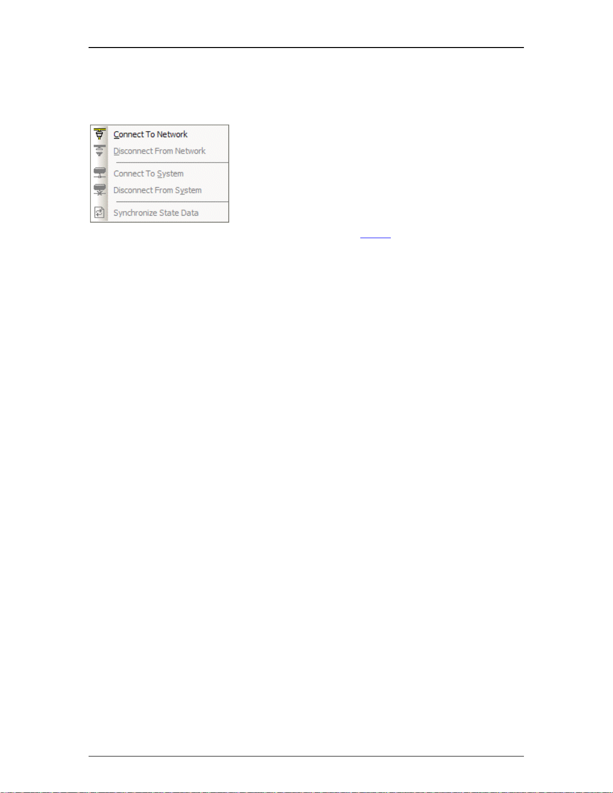
Network Menu
Connect To Network establishes communication with, and
provides a list of, all Audia and Nexia devices on the network.
Disconnect From Network ends communication with all devices
on the network. Connect To System establishes communication
with selected Audia or Nexia systems on the network.
Disconnect From System ends communication with selected
systems on the network. Synchronize State Data manually
updates control data to match system devices.
The menu shows associated toolbar icons.
10
Page 13
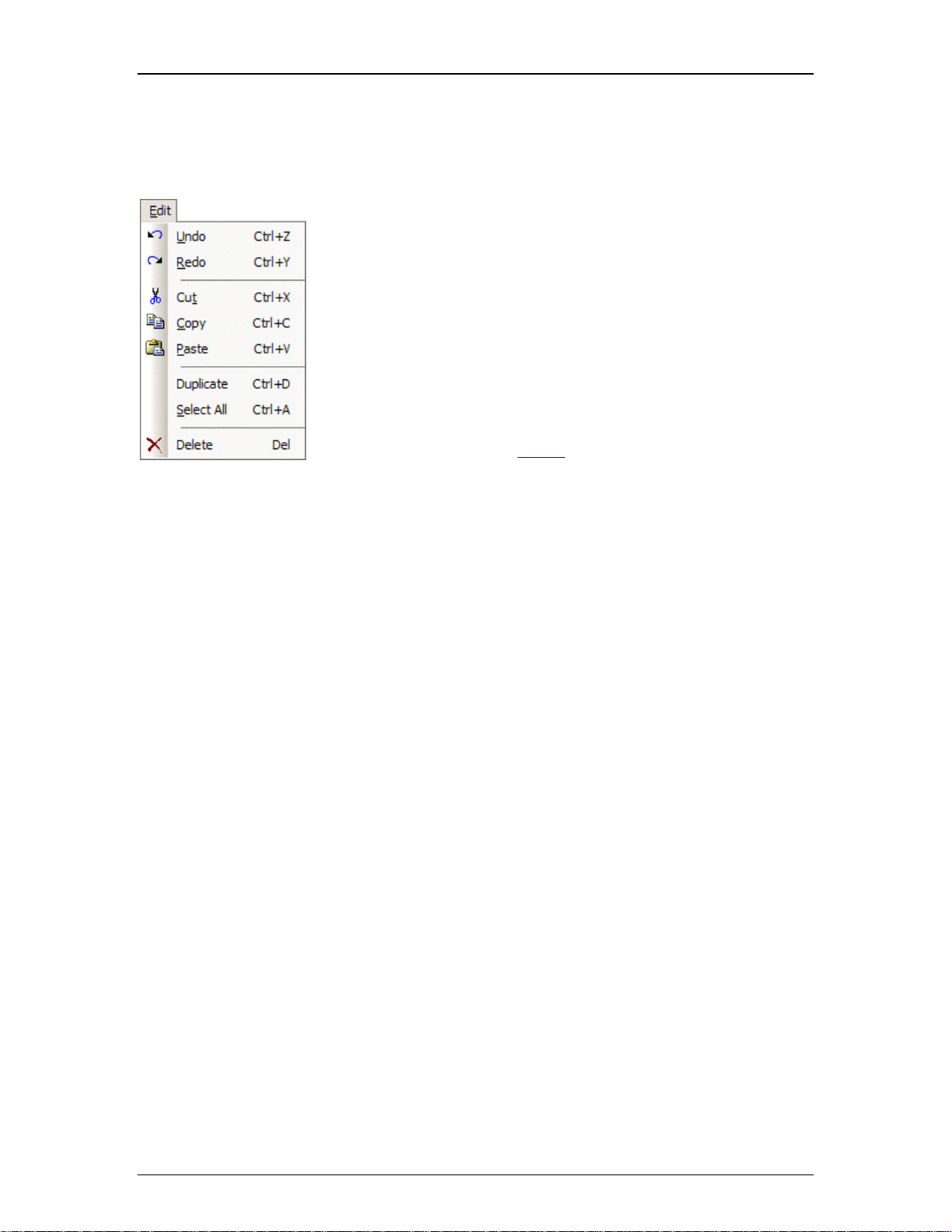
Edit Menu
Edit Menu
Software Tools
Undo cancels the most recent action. Redo cancels the previous
Undo.
Cut moves selected objects to the Clipboard. Copy replicates selected
objects to the Clipboard. Paste places objects from the Clipboard into
the Surface.
Duplicate replicates objects into both the Surface and the Clipboard.
Duplicate works with only one selected object at a time. Select All
chooses all control and non-control related objects in the Surface.
Delete removes selected objects from the Surface, without replicating
them to the Clipboard.
The menu shows associated toolbar icons and keyboard shortcuts.
11
Page 14
daVinci Printed Doc
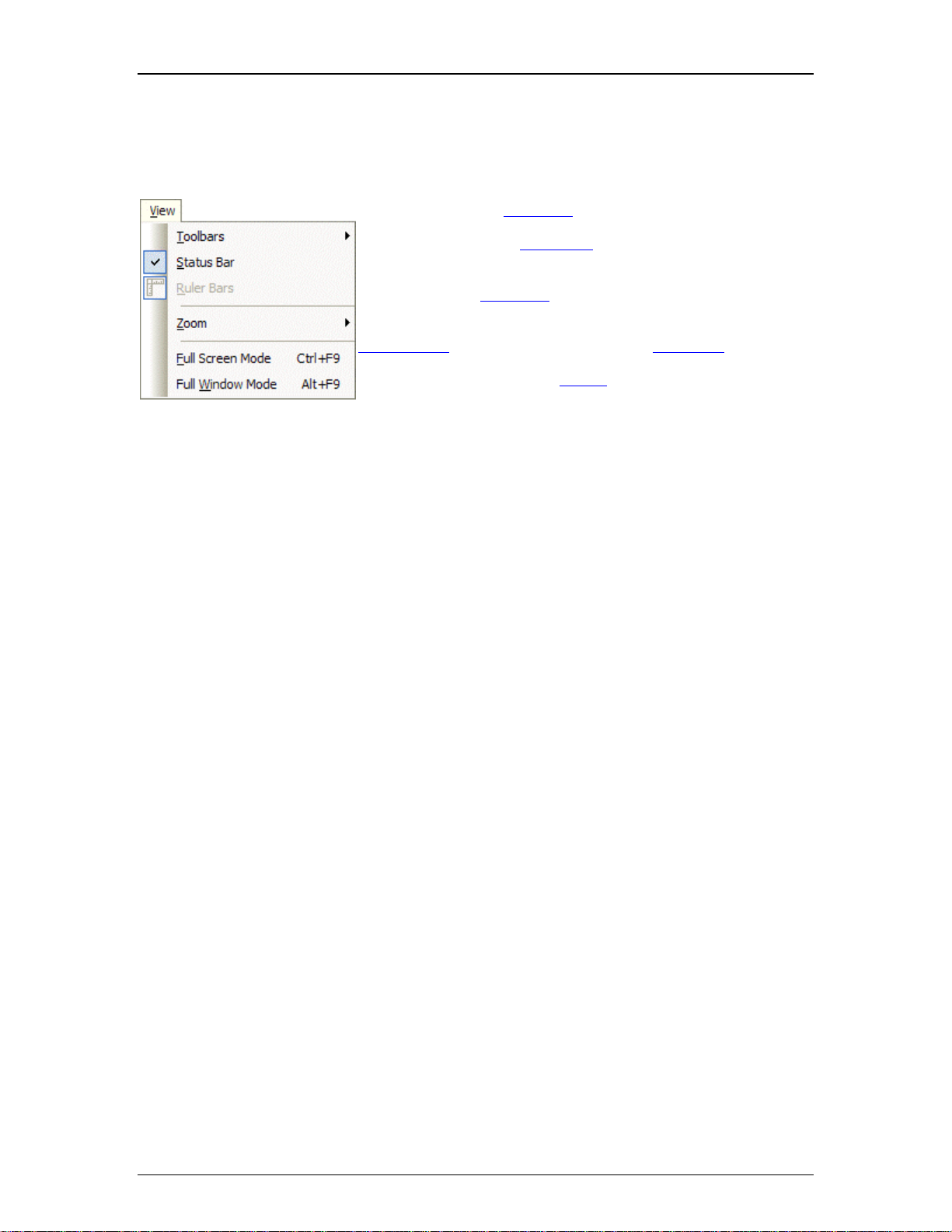
View Menu
View Menu
Toolbars provides a sub-menu of related functions.
Status Bar reveals the Status Bar at the bottom of the Surface.
Ruler Bars reveals rulers along the top and side of the Surface.
Zoom provides a sub-menu of related functions.
Full Screen Mode and Full Window Mode allow the
Administrator
to select one of two different full-screen views.
The menu shows associated toolbar icons and keyboard
shortcuts.
12
Page 15
sub-menus
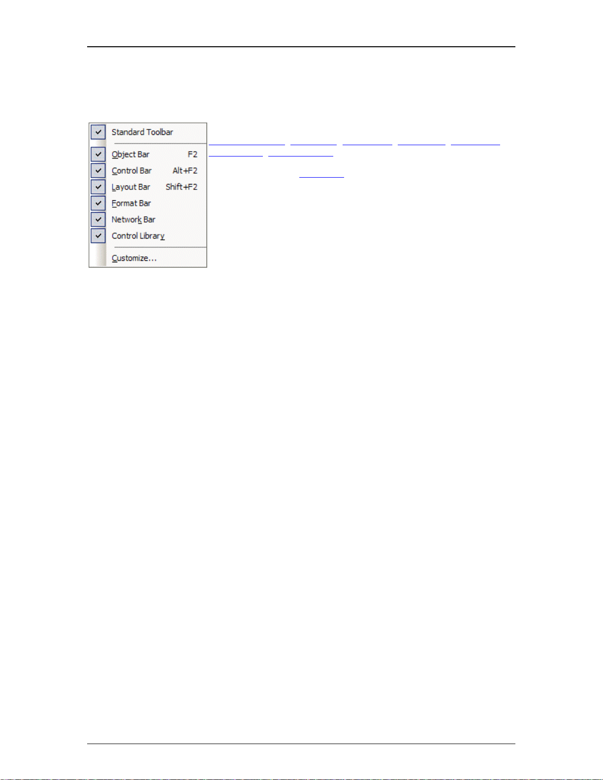
Toolbars Menu
Software Tools
The Toolbars Menu allows the following to be revealed or hidden:
Standard Toolbar
Network Bar
; Object Bar; Control Bar; Layout Bar; Format Bar;
; Control Library.
Customize opens a dialog box for customizing the toolbars.
The menu shows associated keyboard shortcuts.
13
Page 16
daVinci Printed Doc
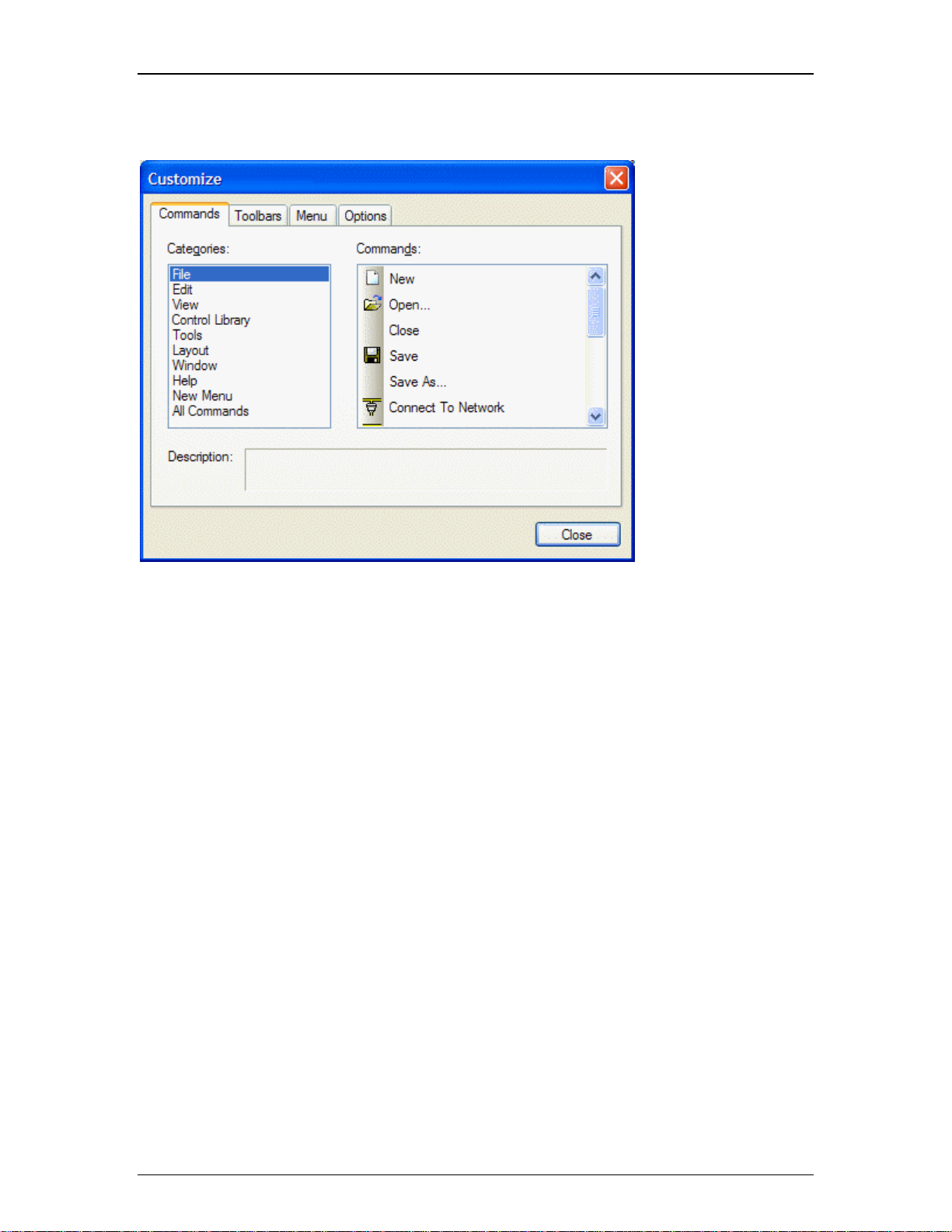
Customize
Customize allows
existing toolbars and
menus to be edited, and
new ones to be created.
Certain aspects of
appearance may also be
personalized.
14
Page 17
Zoom Menu
Software Tools
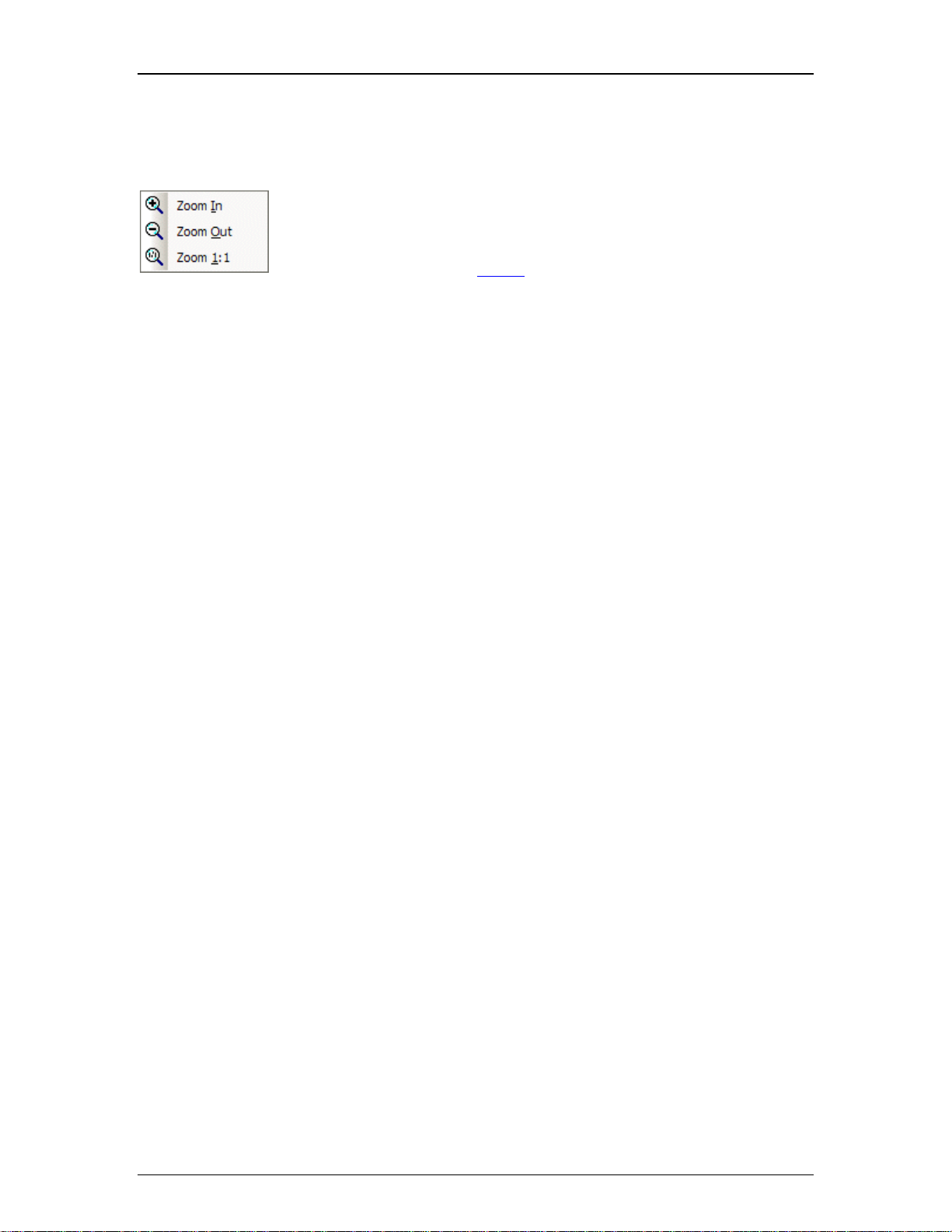
Zoom In increases magnification of Surface in 25% increments. Zoom Out
decreases magnification of Surface in 25% increments. Zoom 1:1 returns
magnification of Surface to 100%.
The menu shows associated toolbar icons.
15
Page 18
daVinci Printed Doc
Control Library Menu
Control Library Menu
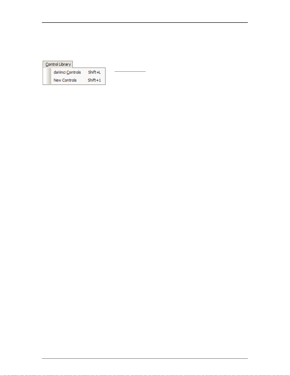
The Control Library Menu provides a list of control categories from
the Control Library
the Control Library opens to that category automatically.
The menu shows associated keyboard shortcuts.
. When a category is selected from the menu,
16
Page 19

Tools Menus
Tools Menu
Software Tools
Passwords provides a sub-menu of related functions.
Options opens a dialog box for adjusting software behavior. The dialog box
has four tabs: General
; Display; Auto-Connect; and Network.
17
Page 20
daVinci Printed Doc
sub-menus
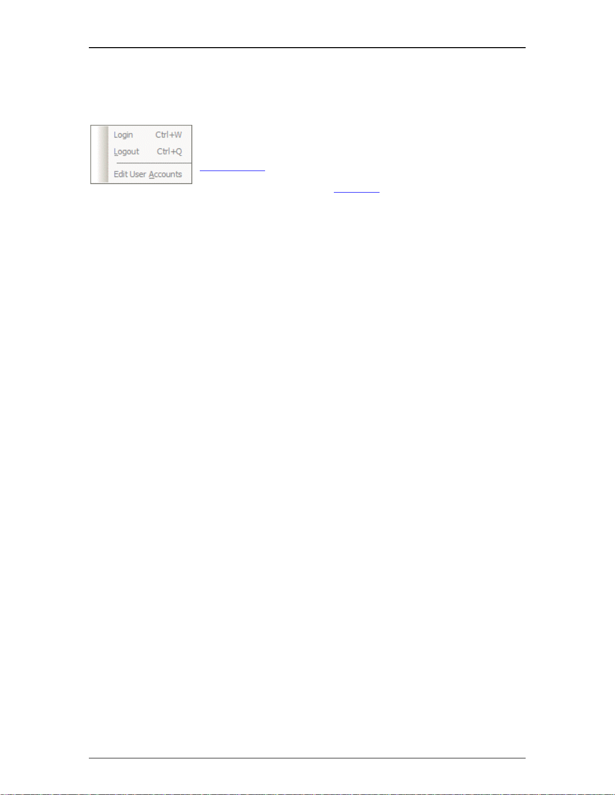
Passwords Menu
Login and Logout allow direct access to a daVinci control surface that
is currently running on a computer connected to the system network.
Login will require a User Name and Password, as established under
User Accounts
Edit User Accounts opens a dialog box for restricting user control
access.
.
The menu shows associated keyboard shortcuts.
18
Page 21
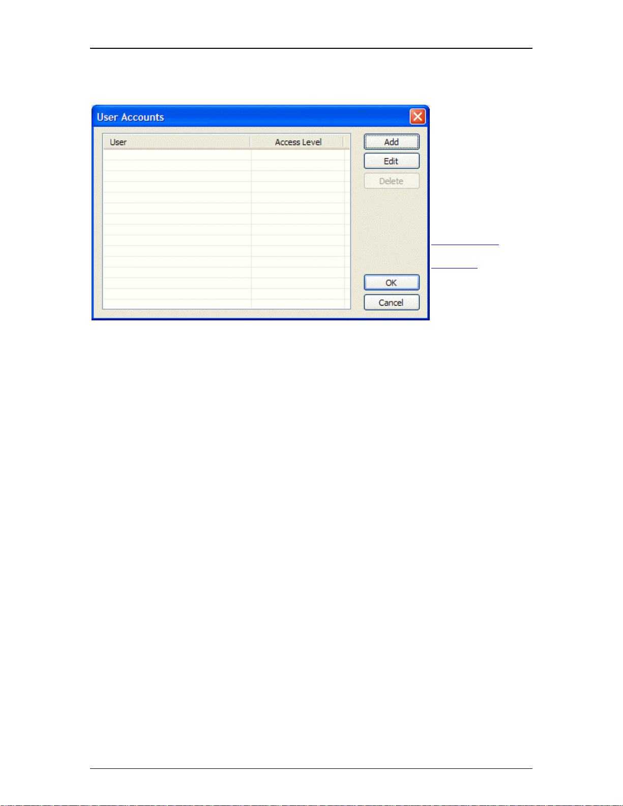
User Accounts
A
Software Tools
User Accounts allow
control access to be
restricted. In addition
to password
protection, a User
name is assigned to
an Access Level.
Individual controls
may be assigned to
one of five prioritized
ccess Levels via the
Property Sheet
. Add
or Edit opens a
dialog box
for
creating accounts.
Delete removes
selected accounts.
OK (off-line) stores
accounts as part of
the daVinci file, which
must then be saved.
Send (on-line) stores
accounts into the
system.
19
Page 22
daVinci Printed Doc
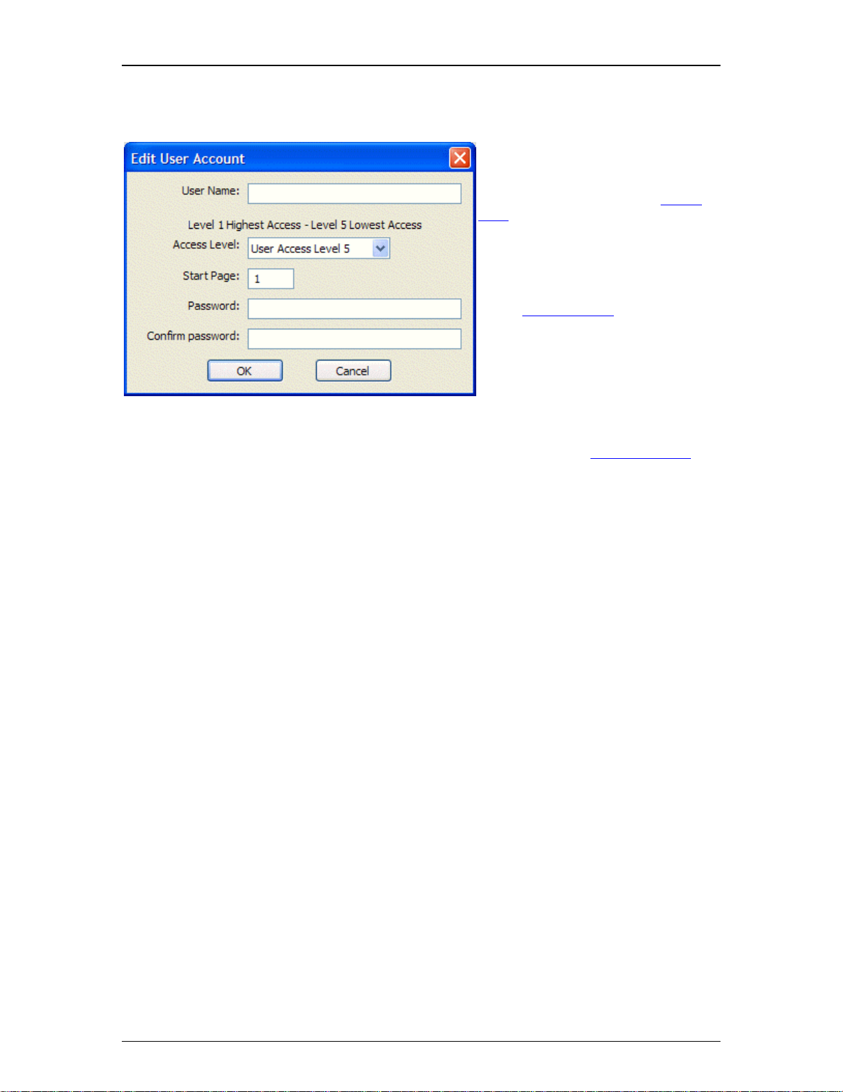
Edit User Accounts
Edit User Account allows creation
and editing of accounts. An account
requires a User Name and Password.
Start Page determines which control
page is to be accessed initially by this
user. An Access Level is also
assigned. The Access Level
determines which controls will be
available to that user. Control objects
are also assigned to Access Levels,
via the Property Sheet
. There are five
prioritized Access Levels. Level 1
accounts can access all controls, Level
2 accounts can access all but Level 1
assigned controls, Level 3 accounts
can access all but Level 1 & 2
assigned controls, and so forth.
Inaccessible controls will be visible,
but disabled. They can instead be
made invisible via General Options
.
20
Page 23
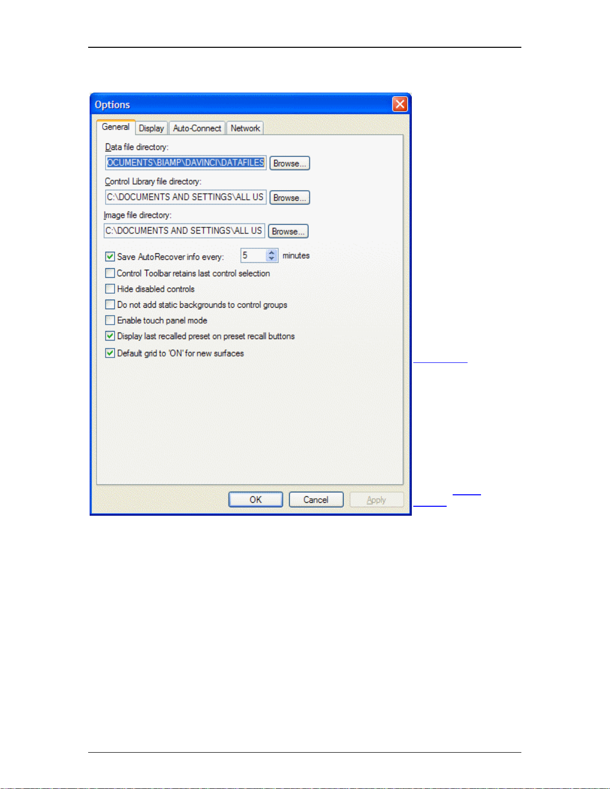
General Options
Software Tools
Data, Control Library,
and Image files may be
saved to specified
directory locations.
Save AutoRecover
time may be adjusted
or disabled.
Control Toolbar
retains last control
selection may be
enabled for repeated
placement into Surface.
Hide disabled
controls may be
enabled so
inaccessible
controls
are hidden instead of
grey.
Do not add static
backgrounds to
control groups
removes the
background image from
grouped objects placed
from the Object
Toolbar.
Enable touch panel
mode removes 'focus
rectangle' from the
selected control.
Display last recalled
preset on preset
recall buttons allows
buttons to display
preset numbers, or
simply the word
'Recall'.
21
Page 24

daVinci Printed Doc
Default grid to "ON"
for new Surfaces may
be disabled, which will
start new files with the
off.
Grid
22
Page 25

Display Options
Software Tools
Application Visual
Style allows a choice of
different styles of
appearance. This
affects various
elements of the daVinci
software.
MDI Tabs affects the
appearance of Multiple
Document Interface
tabs specifically, and
will change the
available Window Menu
items if disabled
Target Display
Resolution is detected
automatically, but can
instead be specified,
which will then provide
boundary markers in
the Surface during
design mode.
23
Page 26
daVinci Printed Doc
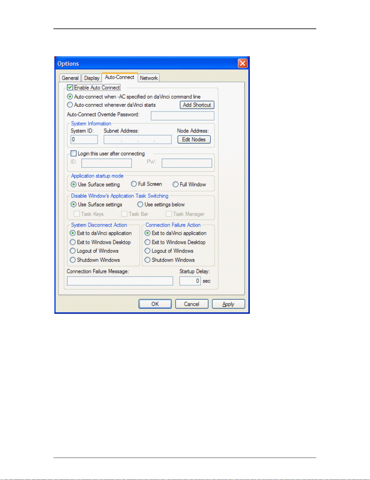
Auto-Connect Options
Enable Auto-Connect
allows the specific
computer to
automatically connect
to a daVinci controlled
system.
Auto-Connect when –
AC specified on
daVinci command line
allows only specific
daVinci shortcuts to
employ Auto-Connect.
Auto-Connect
whenever daVinci
starts forces an Auto-
Connect whenever
daVinci is started.
Add Shortcut will add
a shortcut to the
Startup Folder, the
"Run" Registry Key, or
the Desktop. Shortcuts
in Startup or "Run"
Registry will start
daVinci when the user
logs in.
Auto-Connect
Override Password
allows entry of
password for protection
against Alt key
overrides.
System Information
requires the ID number,
and all device IP
Adresses, for the
system.
24
Login this user after
connecting provides
Page 27

Software Tools
an automatic login for a
specified user (ID and
Password).
Application startup mode selects Use Surface settings (affects all users) or Full Screen / Full
Window (affects specific user). Disable Window’s Application Task Switching selects Use
Surface settings (affects all users) or Use settings below (affects specific user). System
Disconnect Action selects behavior when user disconnects. Connection Failure Action selects
behavior when attempted connection fails (includes entry of customized failure message).
Startup Delay allows for wireless network devices which may be slower to initialize, by adding up
to 120 seconds of manual delay before Auto-Connect startup will time-out.
25
Page 28

daVinci Printed Doc
A
Network Options
Network Device
Discovery Method
allows the user to
choose a method to
Connect To Network
.
UDP Broadcast is the
default 'message'
based routine, which
looks for devices on a
common network. TCP
User Supplied Device
List allows connection
to a specified list of
device IP addresses.
This approach is
'communication' based,
and allows the user to:
avoid firewall conflicts;
create custom device
lists; access multiple
sub-networks; connect
remotely via modem.
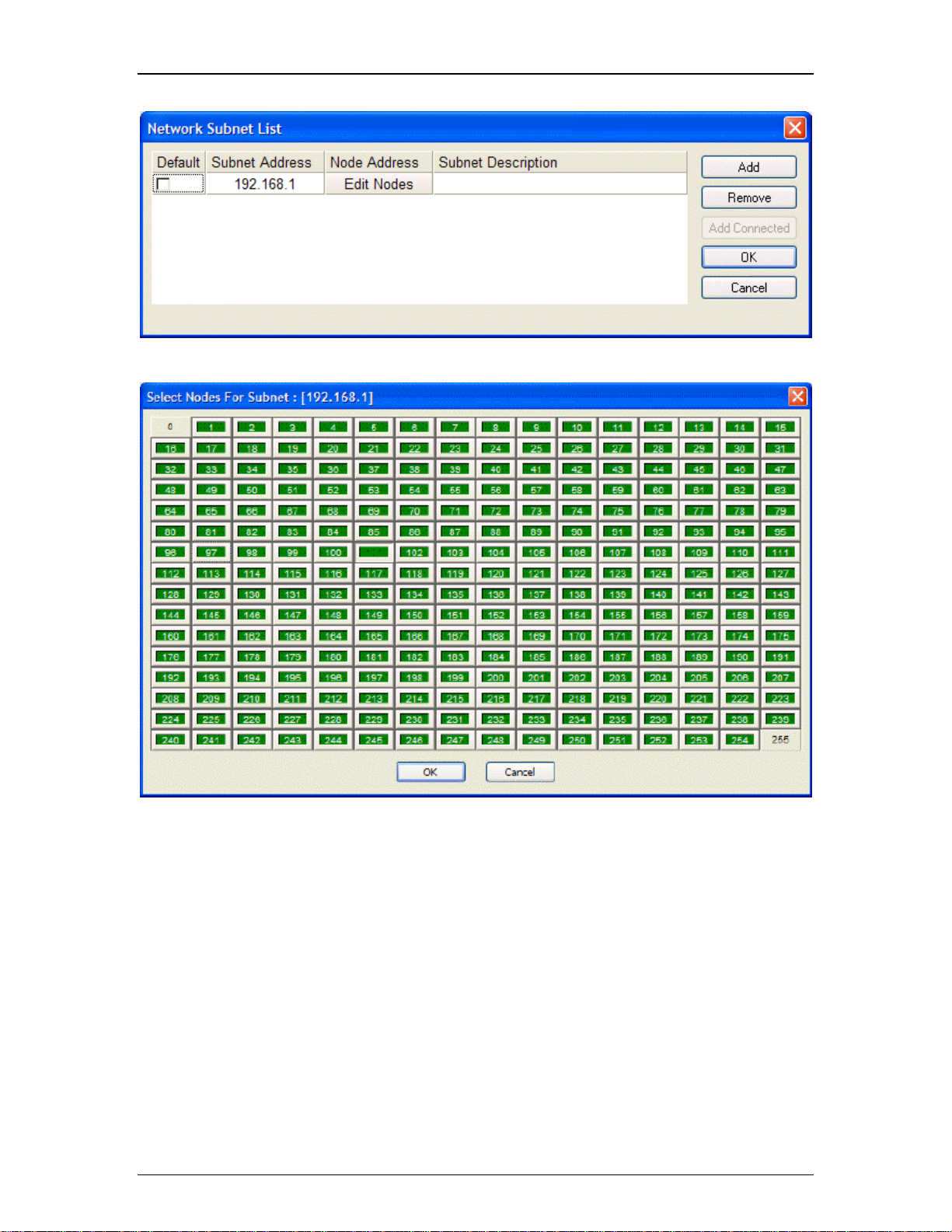
Edit Device List allows
creation of the TCP
User Supplied Device
List. Use Add to create
a new entry, doubleclick under Subnet
ddress, and enter only
the first three sets of
numbers. Then click
Edit Nodes and select
the appropriate final set
of numbers for the
intended device(s).
Default Network
Timeout is a user-
definable period of time
after which software will
timeout if it does not
get a response from
firmware.
26
Page 29
Software Tools
Default Network Interface Card allows selection of a specific network interface card (NIC), when
multiple cards are available on the computer being used to run daVinci software.
27
Page 30

daVinci Printed Doc
Default Network Timeout is a user-definable period of time after which software will time out if it
does not get a response from firmware. If connected to the network at the time of changing the
Default Network Timeout, changes are not applied until the software has disconnected from the
network and reconnected.
28
Page 31

Layout Menu
Layout Menu
Software Tools
Pack Objects, Align Objects, Space Evenly, Center In View,
Make Same Size
menu of related functions.
, Grouping, and Order each provides a sub-
Objects opens the Object Sheet.
Layers opens the Layers Sheet.
Properties opens the Property Sheet.
Edit Gang Groups opens the Gang Group dialog box.
Edit Hotspots provides a sub-menu of related functions.
Control Pages provides a sub-menu of related functions.
Grid Settings opens a Grid Settings dialog box.
Test Mode disables editing and allows off-line testing of controls.
The menu shows associated toolbar icons and keyboard shortcuts.
29
Page 32

daVinci Printed Doc
sub-menus
Pack Objects Menu
Left packs selected objects next to each other, aligned on the left. Right packs
selected objects next to each other, aligned on the right. The target location for
packing Left/Right is the top-most selected object. Top packs selected objects
next to each other, aligned on the top. Bottom packs selected objects next t o
each other, aligned on the bottom. The target location for packing Top/Bottom
is the left-most selected object.
The menu shows associated toolbar icons.
30
Page 33

Align Objects Menu
Software Tools
Left aligns selected objects on the left. Right aligns selected objects on the
right. Top aligns selected objects on the top. Bottom aligns selected objects
on the bottom. Vert. Center aligns selected objects on a vertical center-line.
Horz. Center aligns selected objects on a horizontal center-li ne. The primary
selected object (green handles) becomes the target for alignment.
The menu shows associated toolbar icons.
31
Page 34

daVinci Printed Doc
Space Evenly Menu
Across spaces selected objects horizontally. Down spaces selected objects
vertically. The two most-distant objects become the reference for spacing
evenly.
The menu shows associated toolbar icons.
32
Page 35

Center In View Menu
Software Tools
Both centers selected objects within the visible Surface, both vertically and
horizontally. Vertical centers selected objects vertically within the visible
Surface. Horizontal centers selected objects horizont ally within the visible
Surface.
The menu shows associated toolbar icons.
33
Page 36

daVinci Printed Doc
Make Same Size Menu
Both sizes selected objects both in width and height. Width sizes selecte d
objects in width only. Height sizes selected objects in height only. The primary
selected object (green handles) becomes the reference for sizing.
The menu shows associated toolbar icons.
34
Page 37

Grouping Menu
Software Tools
Group combines selected objects into a single object. Ungroup
separates a grouped object into the individual objects. Regroup
combines the most recently ungrouped objects.
The menu shows associated toolbar icons and keyboard shortcuts.
35
Page 38
daVinci Printed Doc
Order Menu
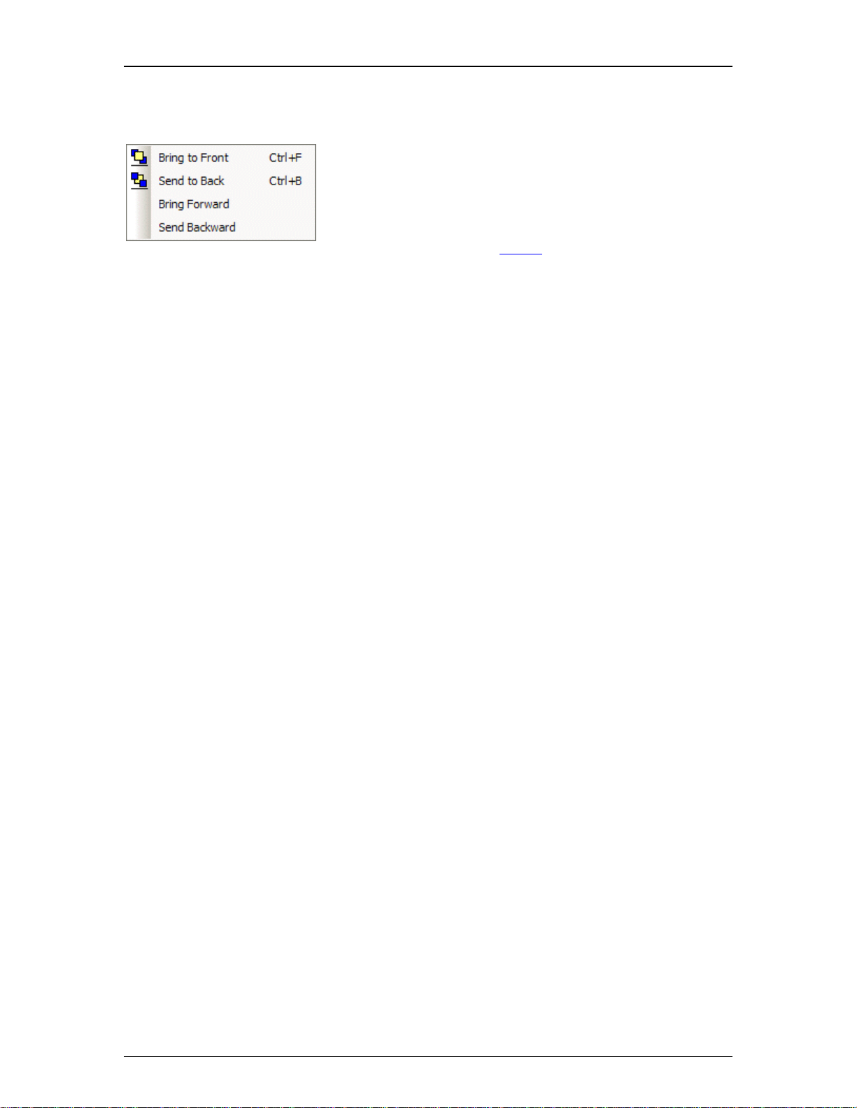
Bring To Front moves selected objects in front of all other
objects. Send To Back moves selected objects behind all other
objects. Bring Forward moves selected objects forward relative
to others. Send Backward moves selected objects backward
relative to others.
The menu shows associated toolbar icons and keyboard
shortcuts.
36
Page 39

Object Sheet
Software Tools
Object Sheet provides a list of
all objects on the current page
of
the Surface. This list includes the
object type and tab order for
each Object Code (unique object
name). When the Object Sheet is
closed, object selection may
done sequentially using the
keyboard Tab key. The Tab
Order for this type of selection
can be changed in the Object
Sheet, by selecting an object in
the list then either dragging it or
using Up and Down. An object
may also be selected directly
from the list.
37
Page 40

daVinci Printed Doc
Layers Sheet
Layers Sheet provides an editable table of Layer
properties. Layers can be used to separate a Surface
into multiple parts. Layers can be organized with
regards to object types, system segments, or any other
criteria. The Default Layer always remains, but other
Layers may be created or removed using Add and
Delete. Layers may be selected directly from the list.
Up and Down change the position of a Layer in the list
only (Layers are not stacked, so this does not affect
Tab Order or visual overlapping). All objects in a given
Layer can be selected with Select. Added Layers may
be given a custom Name. View turns on/off visibility of
a Layer in the Surface. NOTE: Objects cannot be
selected when the current Layer is invisible. Lock
prevents a Layer from being changed or selected. Lock
and View may also be accessed by double-clicking on
the corresponding icons within the list.
38
Page 41

Gang Group
Software Tools
Gang Group allows multiple controls of
the same type to have combined
operation. A Gang Group must first be
created in this list. Then multiple controls
of the same type may be assigned to
that group via the Property Sheet
NOTE: Instance ID (or Instance ID Tag),
DSP Block Type, Attribute, and
Input/Output must be assigned for
objects in a gang, even to achieve
proper control behavior in Test Mode
Gang Groups are created or removed
using Add and Delete.
When a new Gang Group is added, a
Toggle Button control appears, which is
already assigned to gang/un-gang all of
the controls in that Gang Group. Gang
controls may be deleted if not needed.
User-created Toggle Button
controls
may also be assigned as Gang controls.
.
.
When assigning controls to a Gang Group (via the Property Sheet
assigned as Master. Gang Group and Master control behavior varies by control type.
), some or all of the controls may be
Toggle Button controls: When the state of a Master control is toggled (on/off) by clicking on it, other Master
controls in that Gang will also toggle (on/off), regardless of their original state. Non-Master controls will
simply assume the same state (on/off) as the Master control.
Fader, Edit, and Edit Spin controls: When the setting of a Master control is changed, all other controls in that
Gang are changed accordingly, so as to maintain the same relative offsets. The range of the Master control
is restricted, so that no other (offset) controls may travel outside of their range. When a non-Master control
setting is changed, no other controls in that Gang are affected.
Graph controls: Graphs cannot be assigned as Master controls. All Graph controls within a Gang will follow
the active control exactly, on an individual filter basis. With Parametric EQs or All-Pass Filters it is possible
to gang controls that have a different number of filter bands. In this case, only the common filter bands
(those that are first in initial numerical order) are ganged together.
NOTE: If a ganged control is modified as the result of a preset recall, then no ganging behavior occurs.
39
Page 42

daVinci Printed Doc
Edit Hotspots Menu
Edit Points reveals the line connections on a selected Hotspot, for manual
editing of the shape. Additional Edit Points can also be added to the
Hotspot.
Rotate reveals handles on a selected Hotspot, for manual rotation of the
shape. Rotation for a selected Hotspot can also be assigned via the
Property Sheet
The menu shows associated toolbar icons.
40
Page 43

Control Pages Menu
Software Tools
Edit Control Pages opens the Page Selection dialog box.
Previous Control Page reveals the prior page in the
Surface.
Next Control Page reveals the following page in the
Surface.
The menu shows associated toolbar icons and keyboard
shortcuts.
41
Page 44

daVinci Printed Doc
Page Selection
Page Selection provides an editable table of Pages.
Pages can be used to separate a Surface into multiple
parts. Pages can be organized with regards to object
types, system segments, or any other criteria. The
default Page 1 may be re-named, but always remains.
Other Pages may be created or removed using Add
and Delete. Pages may be selected directly from the
list. Up and Down change the position of a Page in the
list, which also affects Page selection order. Any Page
may be given a custom Name.
42
Page 45

Grid Settings
Software Tools
Grid Settings allows the Surface Grid to
be customized. Show Grid turns the
Grid on/off. Snap To Grid forces the
upper-left corner of an object to align
with grid-marks. Margin changes the
location (in pixels) of the blue, dotted
guidelines (initially found near the edges
of the Surface).
43
Page 46

daVinci Printed Doc
Windows Menu
Window Menu
Close will close the active Surface (daVinci file). Close All will close all
currently open Surfaces (daVinci files).
Currently open files are listed at the bottom of the menu, for easy access.
Windows opens a dialog box for working with multiple open files.
The Window menu changes when MDI tabs are disabled under Display
Options.
The menu also shows associated toolbar icons.
44
Page 47

Windows
Software Tools
Activate will
switch to the
selected file.
Save will save
the selected
file. Close
Window(s) will
close selected
files.
45
Page 48

daVinci Printed Doc
Help Menu
Help Menu
Help Topics opens this daVinci Help file.
About daVinci and Show Splash Window open software version
informational screens.
The menu also shows associated toolbar icons.
46
Page 49

Toolbars
Software Tools
47
Page 50

daVinci Printed Doc
Standard Toolbar
Standard Toolbar
Toolbar icon names appear when the mouse is positioned over them.
New, Open, Save, and Print functions are the same as found on the File Menu.
Cut, Copy, Paste, Undo, and Redo functions are the same as found on the Edit Menu.
The Help function is the same as found on the Help Menu.
Toolbars are opened/closed and customized via the View Menu, and may be positioned as
desired.
48
Page 51

Software Tools
Object Bar
Object Bar
Toolbar icon names appear when the mouse is positioned over them.
The Object Bar allows grouped sets of controls, which represent typical system design
components, to be placed into the Surface. These grouped controls are organized in the same
categories as found in the Audia and Nexia design software: Input Output; Mixers; Equalizers;
Filters; Crossovers; Dynamics; Routers; Delays; Controls; Meters; and Generators.
Each category is represented by an icon, with a drop-down menu to the right. To place an object,
first choose the appropriate category, then select the desired component from the drop-down
menu. Once the component has been selected, simply left-click at the desired location in the
Surface. With certain controls, this will produce a pop-up window of configuration options, which
must match the component being controlled. Then, an Instance ID
(or Instance ID Tag) must also
be assigned to match the component being controlled. NOTE: Components m ay instead be
copied from a compiled Audia or Nexia design file, and pasted directly into the daVinci Surface,
eliminating the need to manually set component options and Instance ID.
The Object Bar also provides the option of either a select cursor or a text cursor. The select
cursor (default) is for object selection, placement, and manipulation. The text cursor is for placing
static text objects into the Surface. Text can then be manipulated via the Property Sheet
.
Toolbars are opened/closed and customized via the View Menu, and may be positioned as
desired.
49
Page 52

daVinci Printed Doc
Control Bar
Control Bar
Toolbar icon names appear when the mouse is positioned over them.
The Control Bar allows individual controls to be placed into the Surface. These controls are
categorized strictly by available control types: Picture
Button; Fader; Meter; LED; Grid; Dialer Control, Graph; Paging; and Hotspot.
Each control type is represented by an icon. To place an object, first click on the appropriate
icon, then simply click at the desired location in the Surface. With certain control types, this will
produce a pop-up window of configuration options, which must match the component being
controlled. Then, Data Attributes
must also be assigned to match the component being
controlled. NOTE: Components may instead be copied from a compiled Audia or Nexia d esign
file, and pasted directly into the daVinci Surface, eliminating the need to manually set component
options and Data Attributes.
The Control Bar also provides the option of either a select cursor or a text cursor. The select
cursor (default) is for object selection, placement, and manipulation. The text cursor is for placing
static text objects into the Surface. Text can then be manipulated via the Property Sheet
; Frame; Edit; Edit-Spin; Button; Toggle
.
Toolbars are opened/closed and customized via the View Menu, and may be positioned as
desired.
50
Page 53

Controls
Picture
Software Tools
Pictures are non-control related images that can
be used as backgrounds or for placing logos,
icons, etc. Selecting Picture and clicking in the
Surface will produce the Image Dialog box. Load
allows browsing for desired image files.
Supported file formats include: BMP, JPEG, GIF,
EMF, WMF, TIFF, PNG, & ICO. Paste allows
placing images from the Clipboard. Clear
eliminates the selected image, without placing.
Link references the original image file. Embed
Int. will copy the image to a standard memory
location within Audia or Nexia. Embed Ext. will
copy the image to a dedicated image memory
location (Audia only). File Name allows
embedded images to be given an identifying
name, which appears in the Property Sheet.
Linked files indicate their file name and directory
location. Appearance may be manipulated in the
Surface or edited in the Property Sheet
.
daVinci texture images are stored under Shared
Documents.
51
Page 54

daVinci Printed Doc
Frame
Frames are non-control related images that can be used to frame and label
individual or grouped controls, or entire segments of a control screen.
Appearance may be manipulated in the Surface or edited in the Property
Sheet.
52
Page 55

Edit
Software Tools
Edit controls display values and allow
adjustments via keyboard entry. Integral
controls are used for Logic Delay times
and CobraNet® bundle numbers (whole
numbers only). Floating Point controls
are used for levels (including decimal
values). Appearance may be
manipulated in the Surface or edited in
the Property Sheet
.
53
Page 56

daVinci Printed Doc
Edit-Spin
Edit-Spin controls display values
and allow adjustments via keyboard
entry or mouse. Integral controls are
used for Logic Delay times and
CobraNet® bundle numbers (whole
numbers only). Floating Point
controls are used for levels
(including decimal values).
Appearance may be manipulated in
the Surface or edited in the Property
Sheet.
54
Page 57

Button
Software Tools
Button controls provide momentary behavior, and can be used for mouse
selection of functions such as recalling Presets and sending Command
Strings. Buttons can also be assigned software Application related functions
such as Fullscreen, Start/Stop Audio, User Login/Logout, and Exit daVinci.
Appearance may be manipulated in the Surface or edited in the Property
Sheet.
55
Page 58

daVinci Printed Doc
Toggle Button
Toggle Button controls provide latching behavior, and can be used for mouse
selection of functions such as Muting or Inverting of signals. Toggle Buttons can
also be assigned software Application related functions such as Ganging Controls.
Appearance may be manipulated in the Surface or edited in the Property Sheet
.
56
Page 59

Fader
Fader controls allow mouse adjustment of signal levels. Appearance may be
manipulated in the Surface or edited in the Property Sheet
.
Software Tools
57
Page 60

daVinci Printed Doc
Meter
Meter controls provide display of signal levels. Appearance may be manipulated in
the Surface or edited in the Property Sheet
.
58
Page 61

LED
Software Tools
Presence of signals. Appearance may be manipulated in the Surface or edited in
the Property Sheet
.
LED controls display the status of functions such as Muting, Inverting, and
59
Page 62

daVinci Printed Doc
Grid
Grid controls display and allow mouse selection of
input/output assignments for components such as
Mixers and Routers. Appearance may be
manipulated in the Surface or edited in the Property
Sheet. Right-clicking and selecting ‘Edit Text’ allows
custom labeling of specific inputs/outputs (up to 8
characters).
60
Page 63

Dialer Control Initialization
Software Tools
TI and VoIP controls display and allow
mouse selection of dialing functions for
Telephone Interface components. When
placing a new Dialer control into the Surface,
an Initialization dialog allows selection of
which type of Dialer, Telephone Interface (TI)
or Voice over Internet Protocol (VoIP). After
choosing which typer of Dialer Control is to
be placed, different options are availablewith
respect to which specific controls are to be
included.
Once placed, the selected controls are
grouped together, but may be un-grouped for
editing via the Layout Bar
or Layout Menu.
TI Console
61
Page 64

daVinci Printed Doc
A
VoIP Console
ppearance may be
manipulated in the
Surface or edited in
the Property Sheet
Right-clicking and
selecting ‘Edit Text’
allows custom
labeling of Dial Pad
buttons only.
.
VoIP objects can be placed on the control surface from two different locations. The first location
is from within the I/O menu on the Object toolbar. By placing it from the I/O menu, the user is
able to choose which VoIP lines( Line 1, Line 2, or both, as well as both lines using a combined
console with L1 and L2 selector buttons) are to be used on the control surface. this gives the
user greater flexibility in designing the surface.
The second method is by using the Dialer Control icon
on the Control Bar. This Icon will
open a "Create New Dialer Control" window. At this point the VoIP Console can be selected and
the desired options selected. If it is desired that the control be for line 2, it must be specified in
the Property Sheet.
62
Page 65

Software Tools
Appearance may be
manipulated in the
Surface or edited in
the Property Sheet
.
Right-clicking and
selecting "Edit Text"
allows custom
labeling of Dial Pad
buttons only.
63
Page 66

daVinci Printed Doc
Graph
Graph controls display and allow mouse
adjustment of components such as Equalizers,
Filters, and Crossovers. Appearance may be
manipulated in the Surface or edited in the
Property Sheet
.
64
Page 67

Paging
Software Tools
Paging controls allow mouse navigation between multiple pages of a control
surface. Appearance may be manipulated in the Surface or edited in the Property
Sheet.
65
Page 68

daVinci Printed Doc
Hotspot
Hotspot controls are polygons that are drawn on the Surface, and assigned
Application
This creates a primary Edit Point and begins a line. Release the mouse button at
the desired location to complete the line. Additional Edit Points (and lines) will be
placed with subsequent left-clicks. A Hotspot shape is completed either by rightclicking or by left-clicking back on the primary Edit Point. Hotspots can be edited
via the Layout Menu
or as invisible areas placed over graphic images.
or Paging functions. To draw a Hotspot, left-click and drag the mouse.
and Property Sheet. Hotspots may appear as visible objects
66
Page 69

Software Tools
Layout Bar
Layout Bar
Toolbar icon names appear when the mouse is positioned over them.
Test Mode, Property Sheet, Edit Gang Groups, Layers Sheet, Grouping, Packing, Aligning,
Centering, Spacing, Sizing, Order, Hotspot, and Page functions are the same as found on the
Layout Menu
Toggle Ruler and Zoom functions are the same as found on the View Menu.
Toggle Grid turns the Surface Grid on/off.
Toolbars are opened/closed and customized via the View Menu, and may be positioned as
desired.
.
67
Page 70

daVinci Printed Doc
Format Bar
Format Bar
Toolbar icon names appear when the mouse is positioned over them.
Font, Font Size, Bold, and Italic affect the lettering styles used in object text. Left, Center, and
Right affect paragraph justification of object text. BackColor affects the background of the
Surface or selected objects. TextColor affects the object text. ForeColor affects the lower &
right borders of objects. HiliteColor affects the upper & left borders of objects. PenWidth affects
the borders of objects.
Toolbars are opened/closed and customized via the View Menu, and may be positioned as
desired.
68
Page 71

Software Tools
Network Bar
Network Bar
Toolbar icon names appear when the mouse is positioned over them.
Connect To Network, Disconnect From Network, Connect To System, Disconne ct From
System, and Sync Data functions are the same as found on the File Menu
Send Configuration transmits daVinci control file data to the selected Audia or Nexia system.
Toolbars are opened/closed and customized via the View Menu, and may be positioned as
desired.
.
69
Page 72

daVinci Printed Doc
Status Bar
Status Bar
The Status Bar, along the bottom of the main screen, provides system information. System
status and tool tips are indicated on the far left side. System/network connection status is
indicated in the middle. This includes an indication of LPS (Low Privilege Session) or HPS (High
Privilege Session). When multiple users are connected, HPS is granted to the first user on-line.
Only the HPS user has Administrative access
information, including: number of objects on current page, number of object selected, Layer
status, object location, and object size.
. The right side of the Status Bar indicates Surface
70
Page 73

Keyboard Shortcuts
Keyboard Shortcuts
KEY STROKES COMMAND
Software Tools
file management
Ctrl + Shift + Tab or Ctrl + Shift + F6 previous document
view modes
Ctrl + N create new document
Ctrl + O open saved document
Ctrl + S save document
Ctrl + Tab or Ctrl + F6 next document
Ctrl + F4 close document
Alt + F4 close application
Ctrl + W login
Ctrl + Q logout
Ctrl + E toggle run (test) mode
cut/copy/paste
Ctrl + F9 toggle full screen mode
Alt + F9 toggle full window mode
Ctrl + C copy selected objects
Ctrl + V paste copied objects
Ctrl + D duplicate selected object
Ctrl + X cut selected objects (copy)
Del delete selected objects (no copy)
Alt + drag selected objects duplicate (to Surface or Library)
71
Page 74

daVinci Printed Doc
layout
undo/redo/print
Ctrl + F move selected objects to front
Ctrl + B move selected object to back
Ctrl + A select all objects
Ctrl + G group selected objects
Ctrl + U ungroup selected objects
Ctrl + R regroup
Ctrl + J go to next page
Ctrl + H go to previous page
Ctrl + Z undo
Ctrl + Y redo
tools
Alt + drag within Layout Zoom to target
Processing Library
Ctrl + P print
Ctrl + L Display/Hide Property Sheet
Ctrl + I Display/Hide Object Sheet
Ctrl + M Page Selection Dialog
F2 toggle Object Toolbar
Shift + F2 toggle Layout Toolbar
Alt + F2 toggle Control Toolbar
F1 Help
72
Ctrl + 1~0 Custom Processing Libraries 1~10
Page 75

Designing Control Surfaces
Placing Objects
Start the daVinci software program, and
close any unwanted files that may have
opened automatically from a previous
session. Start a new file
Audia or Nexia as the type of system to be
controlled. To continue working with a
previously saved file, open
NOTE: File extensions are: .dva for Audia
and .dvn for Nexia.
Begin placing control objects into the
Surface
ways:
and select either
that file instead.
. This can be done in three different
1) Place individual controls from the Control Bar. Individual controls must then have Data
Attributes assigned to them via the Property Sheet
. Data Attributes include the Instance ID (or
Instance ID Tag), DSP Block Type, Attribute, and Input/Output for the specific component
being controlled. This information must be available from the Audia or Nexia system design file.
Control Bar
2) Place grouped sets of controls from the Object Bar. Controls from the Object Bar represent
typical Audia or Nexia system design components. Therefore, only an Instance ID (or Instance
ID Tag) is required for the group as a whole (all other Data Attributes are pre-assigned). The
Instance ID (or Instance ID Tag) is assigned via the Property Sheet
information must be available from the Audia or Nexia system design file.
, by first disabling 1By1. This
Object Bar
3) Copy component objects from a compiled Audia or Nexia system design file, and paste them
directly into the daVinci Surface. Data Attributes are automatically copied from the system
design component(s) into the resulting daVinci control object(s), and do not
via the Property Sheet
the types of component(s) copied.
. The resulting controls will be individual and/or grouped depending upon
require assignment
Note: Preset names can only be copied into daVinci independently of the blocks, by right-clicking
the Preset block in the system design file, selecting Copy Preset Labels, then right-clicking over
the associated control in the daVinci file and selecting Paste Preset Labels.
73
Page 76

daVinci Printed Doc
daVinci
Result of Router copied from Audia to
74
Page 77

Customizing Appearance
The position of an object may be changed by dragging the object within the
Surface. The size and shape of an object may be changed by dragging the
green handles that appear when the object is selected. Position, size, and
shape may also be edited in the Display Attributes of the Property Sheet
The color of various aspects of an object may be edited in the Format Bar and
in the Display Attributes of the Property Sheet
be edited include: On/Off, Text, Border, Back, Fore, Hilite, and Shadow.
Certain objects allow more in-depth editing of appearance,
including such aspects as: Border Style & Width, Scale
Markings, Button or Thumb (knob) Style, Control Orientation,
etc.
Textures may be applied as the background for certain objects.
Textures are images imported via the Display Attributes of the
Property Sheet
Bar, for use as Surface backgrounds or placement of logos, etc.
Textures and Pictures both utilize the Image Dialog
may be placed from the Control Bar
associated controls. Text (Static Controls) may be placed from
either the Object Bar
also help organize and label, as well as provide backgrounds for,
other controls. Pictures, Frames, and Text/Static Controls may be
Grouped
and positioned as one object. The appearance of the Surface
itself can be edited in ways similar to those described above.
Designing Control Surfaces
.
. Some color aspects that may
. Pictures may also be imported, from the Control
box. Frames
, for organizing and labeling
or the Control Bar. Text/Static Controls can
with associated controls, so they might all be selected
75
Page 78

daVinci Printed Doc
Adding Control Pages
Control Pages can be used to separate a Surface
into multiple parts. Control Pages can be organized
with regards to object types, system segments, or any
other criteria. Control Pages may be added to the
control surface via the Layout Menu
or Layout Bar.
Once new Pages have been added, Paging
Controls may then be placed on each page from the
Control Bar
. When Paging Controls are placed onto a
Page, a Page List will appear, allowing controls to be
assigned for navigation to specific other Pages within
the control surface.
Paging Controls may be assigned to their own Pages,
as well as to other Pages. This type of assignment
produces a set of buttons that indicates the currently
selected Page.
Hotspots may also be assigned as Paging Controls.
Page access can be password
assigning Access Levels
User Accounts
may also be edited.
. The appearance of Paging Controls
restricted, by
to the Paging Controls in
76
Page 79

Application Controls
Designing Control Surfaces
Certain objects may be assigned to perform
special Application functions, under DSP
Block Type in the Data Attributes tab of the
Property Sheet
.
Button and Hotspot controls may be
assigned the following types of Application
functions:
Full Screen selects a full-screen view or Full
Window selects a minimizable window view
of the control surface. NOTE: Full Screen
view or Full Window view can be selected to
be automatic, under Tools>Options>Auto-
Connect.
Open Popups allows a specified group of
otherwise hidden Popup Controls
revealed.
to be
Start/Stop Audio allows audio signals to be
muted or un-muted for the entire system
being controlled.
User Login/Logout allows controls to be
placed on the control surface for
Login/Logout
.
Exit daVinci ends the current control
session and exits
the daVinci program.
Toggle Button controls may be assigned the
following types of Application functions:
Ganging Controls allows controls in a
common Gang Group
ganged.
to be ganged or un-
77
Page 80

daVinci Printed Doc
Adding Popup Controls
Besides adding Control Pages as a means
to organize the Surface
, Popups allow
specified controls, or groups of controls, to
be hidden or revealed on a given Control
Page. Specifying the affected controls, and
providing Popup buttons is done via the
Property Sheet
.
First, select the control(s) to be affected
and assign EnablePopup (1-Yes) under the
Display Attributes tab in the Property
Sheet. Assign ShowCloseButton (1-Yes) if
individual controls should have dedicated
Close (hide) buttons.
Place a Button or Hotspot control. Then,
assign DSP Block Type (Application) and
Service (Open Popups) under the Data
Attributes tab in the Property Sheet.
The Popup Button may be password
protected by assigning Enable Popup
Password (1-Yes) and entering a Popup
Password.
Select the elipsis (...) to the right of Popups
to provide a list of enabled controls on that
page. Check which controls are to be
revealed with this Popup Button. A master
Close (hide) button for all enabled controls
on that page may also be created by
placing a Popup Button with none of the
enabled controls checked.
One example of using Popup Buttons is
when there are multiple channels to be
controlled, such as in a large mixing
environment. Instead of displaying identical
controls for several channels, the controls
for each channel may be assigned to a
dedicated Popup Button. The channel
controls can then be overlaid, so that only
one channel is revealed at a time, but in the
same location. Next to this single 'channel
strip' of controls, are the Popup Buttons
that select which channel is currently
accessible.
78
Page 81

Designing Control Surfaces
Testing Control Surfaces
Test Mode may be entered at any time during the design process, from either the Layout Menu
or the Layout Bar
Property Sheet
be tested 'off-line'. Test Mode will automatically enter Full Screen mode, if selected under
Tools>Options>General
Mode. Entering Test Mode will also produce a prompt to save any changes that may have been
made to the file.
. Test Mode temporarily disables all editing of the control surface, closes the
and Control Library (if open), and allows the operational behavior of controls to
. NOTE: Ctrl+F9 may be used to toggle Full Screen while still in Test
79
Page 82

Sending Control Surfaces
Network Considerations
The computer must have a 10/100 BaseT network card (NIC) installed. When connecting
directly to the Ethernet port on a single Audia®
used. When connecting to a network (or system) of multiple Audia or Nexia units, a 'straight through' CAT5 cable is used (via an Ethernet switch). If Ethernet switches are 'managed', be
careful to assign all connections to 10 BaseT.
Ethernet has a cable length limitation of 100 meters, between the Ethernet switch and an Audia
or Nexia device. However, fiber-optic cable may be used to extend this distance limitation to 2
km. Fiber-optic cable can be used with switches that have fiber-optic ports, or media converters
can be used to interface fiber-optic cable with standard RJ-45 ports.
The computer must be assigned an IP address (under Network Card Settings>Properties). Most
computers set TCP/IP address automatically, but Audia and Nexia devices require manual
assignment. During the Audia or Nexia system design, each unit will have been set to a unique
IP address (example: 192.168.1.101 and 192.168.1.102). This information must be available
from the system design file. The computer must then be assigned to that same network, but
also with a unique IP address (example: 192.168.1.200).
or Nexia® unit, a 'cross-over' CAT5 cable is
Many system designs require only a single Audia or Nexia device. These are systems where
the number of inputs/outputs, and the amount of DSP processing, does not exceed that of a
standard configuration. When a single unit is used, network considerations are simplified. The
only Ethernet connection is that between the computer and the Audia or Nexia
device ('cross-
over' CAT5 cable). A 'cross-over' cable is included with each device. NOTE: Audia systems
may include similar (but separate) network connections for CobraNet ®. Nexia systems may
include separate connections for NexLink, which utilize 'straight-through' CAT5 cables only.
80
Page 83

Sending Control Surfaces
Accessing Control Surfaces
Once the computer is prepared for communication, use the File Menu or Network Bar to Connect
To Network. This produces a System Connect screen, allowing the appropriate system to be
selected from the System List.
Open Control Surfaces retrieves any daVinci file that has already been sent to the system. This
will require a User Name and Password, as established under User Accounts
Send Control Surfaces stores the currently open/active daVinci file into the system. Update
User Accounts allows changes to the daVinci file User Accounts
Control Surfaces allows any existing daVinci file to be removed from the system. NOTE: Send
Control Surfaces, Update User Accounts, and Clear Control Surfaces require an 'Administrator'
password. The Administrator password can be either the 'Designer' level or 'Te c hnician' level
password from the Audia or Nexia system design itself (not the daVinci file). The 'Administrator'
must also be connected at the 'High Privilege Session' position (first connected user) a s indi cated
in the Status Bar
.
.
to be sent to the system. Clear
81
Page 84

daVinci Printed Doc
Preparing Control Surfaces
Typically, there will be one or more dedicated computers connected to the network, with daVinci
software running, and user access to the control surface available via Login/Logout
that the control surface first be sent
to the system.
The control surface is initially sent to the system by the Administrator, who can utilize certain
Application Controls
to prepare the control surface for the end-user. These Application Controls
would have been included in the control surface design, and assigned to a re stricted User
Access Level. The Administrator can use these controls to put the control surface into a 'user
mode' (such as Full Screen), which the end-user cannot exit from. The Administrator will then
Logout of the control surface, leaving it active on the computer(s) for user Login/Logout
Login/Logout may also be assigned to Application Controls on the control surface, which can be
made accessible to the end-user. Full Screen mode can be automatic whenever control surfaces
are opened or tested, as selected under Tools>Options>General
.
. This requires
. NOTES:
82
Page 85

Using Control Surfaces
Using Control Surfaces
Typically, there will be one or more dedicated computers connected to the network, with daVinci
software running, and user access to the control surface available via Login/Logout
Login/Logout controls may also be available on the control surface. Login requires a User Name
and Password, as established under User Accounts
If the control surface in unavailable (daVinci software and/or computer shut down), then the user
may need to Connect To Network
bypass some 'user mode'
settings established by the Administrator.
and Open Control Surfaces. NOTE: This approach may
.
. Dedicated
83
Page 86

Page 87

Index
85
Page 88

A
Align Objects Menu..................................................... 27
Application Functions.................................................. 71
Architect s & Engineer s Specification ..........................2
Auto-Connect Options................................................. 22
B
Button.......................................................................... 51
C
Center In View Menu ..................................................29
Control Bar.................................................................. 46
Control Library ..............................................................6
Control Library Menu ..................................................15
Control Pages Menu ................................................... 37
Creating Pages ........................................................... 70
Customize Toolbars ....................................................13
Customizing Control Objects ......................................69
D
Designing Control Surfaces ........................................ 68
Display Options........................................................... 21
Documentation.............................................................. 3
E
Edit.............................................................................. 49
Edit Hot Spots Menu ................................................... 36
Edit Menu.................................................................... 10
Edit User Accounts .....................................................19
Edit-Spin .....................................................................50
F
Fader........................................................................... 53
File Menu ...................................................................... 8
Format Bar .................................................................. 63
Frame.......................................................................... 48
G
Gang Group ................................................................ 35
General Options.......................................................... 20
Graph .......................................................................... 59
Grid ............................................................................. 56
Grid Settings ............................................................... 39
Grouping Menu ........................................................... 31
H
Help Menu................................................................... 42
Hotspot........................................................................ 61
K
Keyboard Shortcuts ....................................................66
L
Layers Sheet .............................................................. 34
Layout........................................................................... 4
Layout Bar .................................................................. 62
Layout Menu............................................................... 25
LED............................................................................. 55
M
Make Same Size Menu .............................................. 30
Meter .......................................................................... 54
N
Network Bar................................................................ 64
Network Considerations ............................................. 74
Network Menu .............................................................. 9
Network Options ......................................................... 23
O
Object Bar................................................................... 45
Object Sheet............................................................... 33
Order Menu ................................................................ 32
P
Pack Objects Menu .................................................... 26
Page Selection ........................................................... 38
Paging ........................................................................ 60
Passwords Menu ........................................................ 17
Picture ........................................................................ 47
Popup Controls........................................................... 72
Preparing Control Surfaces ........................................ 76
Property Sheet.............................................................. 5
S
Sending Control Surfaces........................................... 75
Space Evenly Menu.................................................... 28
Standard Toolbar........................................................ 44
Status Bar................................................................... 65
T
Testing Control Surfaces ............................................ 73
TI 57
TI2 Dialer .................................................................... 57
Toggle Button ............................................................. 52
Toolbars Menu............................................................ 12
Tools Menu................................................................. 16
U
User Accounts ............................................................ 18
Using Control Sufaces................................................ 77
V
View Menu.................................................................. 11
VoIP............................................................................ 57
VoIP Console.............................................................. 57
86
Page 89

Index
W
What is daVinci? ........................................................... 1
Window Menu ............................................................. 40
Windows ..................................................................... 41
Z
Zoom Menu ................................................................ 14
87
 Loading...