

Page 1
801i
Mic/Line Mixer
Operation Manual
Biamp Systems | 9300 S.W. Gemini Drive | Beaverton, OR | 97008 | USA | +1.503.641.7287 | www.biamp.com
Page 2

g
Introduction
Front Panel
Rear Panel
Remote Control
Specifications & Block Diagram
Warranty
TABLE OF CONTENTS
pg. 1
pg. 2
pg. 3
. 4
p
pg. 5
pg. 6
July, 2009
Page 3

801
g
y
year
INTRODUCTION
The 801i is a single rack-space mixer, with ei
balanced, discrete transistor preamplifier for low noise and low distortion performance. Special features, including a limiter and remote
level control, make the 801i extremely versatile. The 801i mixer is dependable, easy to install, simple to operate, and carries a fivewarranty.
801i features include:
♦ eight differential balanced mic/line inputs & one aux line input
♦ discrete transistor mic/line preamps for low noise & distortion
♦ +24 volt phantom power selectable on each mic/line input
♦ aux input switch selectable for balanced or stereo summing
♦ aux input 'auto-ducking' switch selectable on channels 1~8
♦ front panel trim and rear panel pad switch on each channel
♦ +10dB 'peak' LED indicator on each channel for easy set-up
♦ high-pass 'rumble' filter switch selectable on each channel
♦ mic/line & aux inputs on plug-in barrier strip connectors
ht mic/line inputs and one auxiliary line input. Each mic/line channel uses a differentiall
♦ unbalanced direct output terminal on each input channel
♦ balanced main output on plug-in barrier strip connector
♦ main output limiter with threshold control and LED indicator
♦ main out Bass & Treble control with rear panel bypass switch
♦ -20dB signal present & power LED indicators at main output
♦ channel 1 automatic override assignable on other channels
♦ optional remote control of main out via external level control
♦ stack in & slave switch to add inputs by linking multiple units
♦ covered by Biamp Systems' five-year warranty
♦
marked and UL / C-UL listed power source
1
Page 4
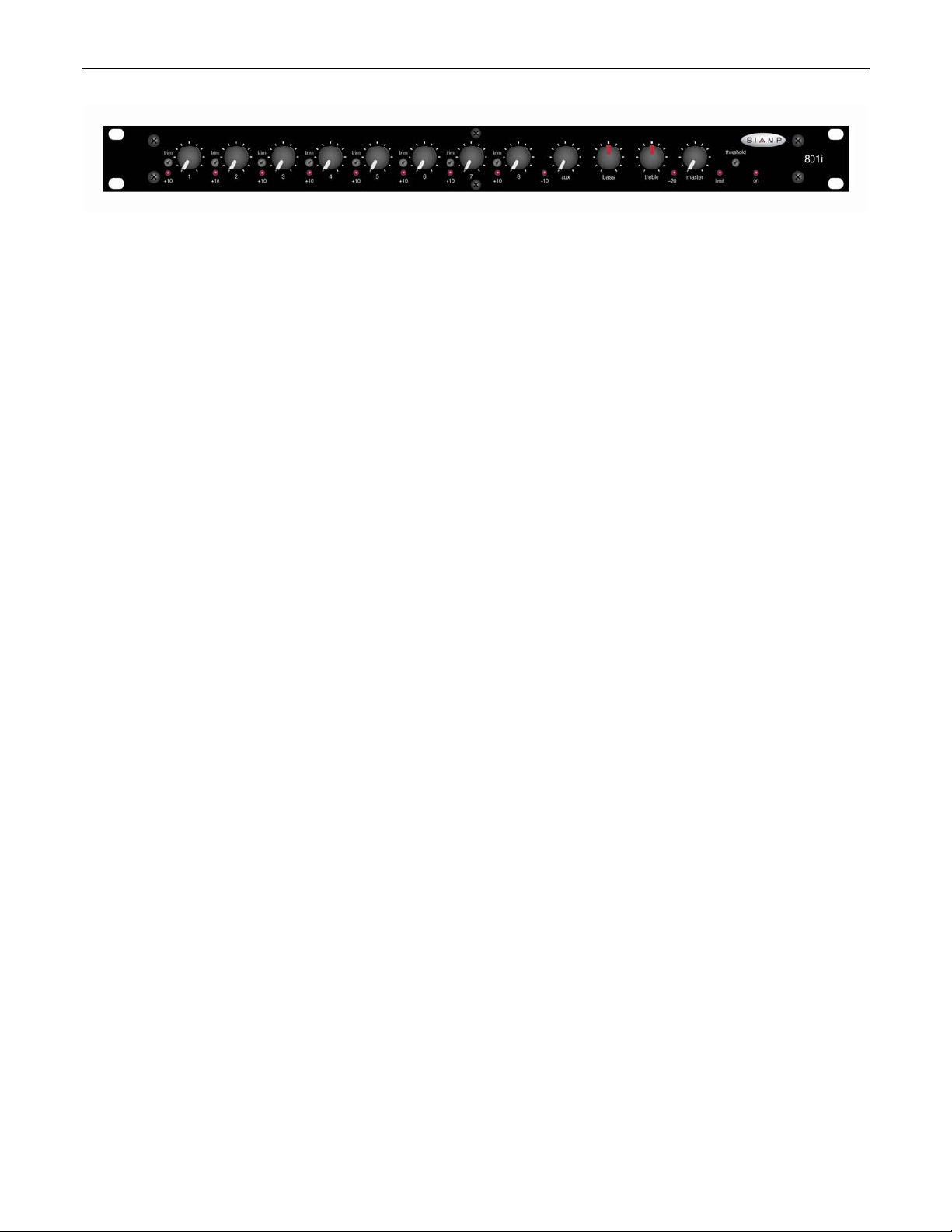
FRONT PANEL
+10 Indicator (Channels 1~8 & Aux): These red LEDs will light
whenever channel signal levels reach +10dB (8dB below clipping).
Use this feature to aid in adjusting the Trim controls (see below).
Trim (Channels 1~8): These screw-driver adjustable controls set
the channel gain (0~60dB) to compensate for different input signal
levels. For best performance, adjust these controls so the channel
+10 indicators flash only on occasional peaks. If input signal
exceeds the normal operating range of the Trim control, assign the
rear panel Pad switch (see DIP switches on next page).
Level (Channels 1~8 & Aux): These controls adjust the amount of
signal sent from the individual input channels to the mixer output
section. Optimum Level settings are near the 12 o'clock position
(unity gain).
Bass: This control provides low-frequency tonal adjustment
(±10dB @ 100Hz) for signals at Main Patch & Main Output.
Treble: This control provides high-frequency tonal adjustment
(±10dB @ 10kHz) for signals at Main Patch & Main Output.
-20 Indicator: This red LED will light whenever signal levels reach
-20dB (signal present) at Main Output.
Master: This control adjusts the level of overall signal sent to
Main Output. Optimum Master settings are near the 12 o’clock
position (unity gain) or below.
Threshold: A limiter is provided at Main Output to help eliminate
unwanted peaks in signal level. This screw-driver adjustable
control sets the level at which the limiter will be activated. For
most applications, set Threshold so the limiter is activated only by
occasional peaks. Counter-clockwise adjustment lowers
Threshold, increasing the amount of limiting. Clockwise
adjustment raises Threshold, decreasing the amount of limiting.
Threshold is factory set fully clockwise, effectively removing the
limiter from operation.
Limit: This red LED will light whenever signal levels exceed the
threshold, thereby activating the limiter.
On Indicator: When the power transformer is plugged in, and AC
power is applied to the 801i, the red On indicator remains lit.
2
Page 5

REAR PANEL
DC Power Supply: The included power supply module provides
24 Volt DC power to the mixer. It is connected to the DC Power
Jack on the rear side of the mixer. To ensure compatibility, only
use a Biamp Systems supplied power supply.
Main Output: This plug-in barrier strip provides the balanced linelevel Main Output from the mixer. For balanced connection, wire
high (+), low (-), and ground (
high (+) and ground (
d
). For unbalanced connection, wire
d
), leaving (-) unconnected. Signal level will
be reduced by 6dB when output is unbalanced. Main Output level
is affected by the front panel Master control, as well as by remote
control (see Remote below).
Stack In: This plug-in barrier strip provides the balanced line-level
Stack In to the mixer. Signal entering here is combined with
signals from the input channels, and is then sent to the Main
Output section. When using multiple 801i mixers within a system,
connect Main Output of one mixer to Stack In of the next mixer,
and so forth. All mixers except the final 801i should be assigned
as ‘slaves’ (see Master DIP Switches below). For balanced
connection, wire high (+), low (-), and ground (
connection, wire high (+) and ground to both (
d
). For unbalanced
d
) & (-).
Remote: This plug-in barrier strip provides connection for an
optional remote master level control (model RP-L1) (see Remote
Control on pg. 4). An external potentiometer (5k~50k ohm linear
taper) or external ramp voltage (0~+10VDC) can also be used.
Potentiometers are wired high (V), wiper (C), and low (
voltage is wired positive (C), and ground (
d
). The Remote port
d
). Ramp
must be enabled before remote master level control is possible
(see Master DIP switches below).
Input & Direct Out (Channels 1~8 & Aux): These plug-in barrier
strips provide the balanced mic/line Inputs to the mixer (Channels
1~8 only). For balanced connection, wire high (+), low (-), and
ground (
to both (
d
). For unbalanced connection, wire high (+) and ground
d
) & (-). Phantom power (+24VDC) is available for
condenser microphones (see DIP Switches below). The Aux input
accepts either balanced mono line input or unbalanced stereo line
input (see DIP switches below). Aux input cannot accept mic input
signal, and does not provide phantom power. Unbalanced 'prefader' Direct Outputs are available on Channels 1~8 & Aux, using
the (d. out) & (
d
) terminals.
Master DIP Switches: These switches assign functions to the
mixer as a whole (when pushed up). Slave
assigns the mixer as
an expander to a ‘master’ mixer. Tone Out bypasses the front
panel tone controls (Bass & Treble). Override allows automatic
muting of other inputs when signal is present in Channel 1.
Remote
allows remote control of Main Output level, by enabling
the Remote terminals (see above).
DIP Switches (Channels 1~8 & Aux): These switches assign
functions to the individual inputs (when pushed up). Pad
attenuates channel signal -18dB (-10dB at Aux) for line input.
Priority
disables Channel 1 Override muting for that channel.
Phantom
condenser mics). Duck Aux
(Channels 1~8 only) turns on phantom power (for
(Channels 1~8 only) allows channel
signal presence to activate -15dB attenuation at Aux input
(ducking). HP Filter
(6dB/octave @ 170Hz). Sum
enables a high-pass filter on the input
(Aux only) converts Aux from
standard balanced input to stereo (L/R) summing input.
3
Page 6

Remote Control
Remote: The output level of an 801i mixer can be remotely controlled via an external potentiometer (5k~50k ohm linear taper) or ramp
control voltage (0~+10VDC). An RP-L1 remote control panel is available as an option (see diagram below). Potentiometers are wired high
(V), wiper (C), and low (
before remote control of output level is possible (see Master DIP Switches on pg. 3). Remote control does not change physical settings on
the 801i mixer, it only attenuates from the maximum level settings established at the mixer.
d
). Ramp voltage is wired positive (C) and ground(d). The Remote port of the 801i mixer must be enabled
REMOTE
RP-L1
high (cw)
white (to 'V')
w
CV
cwccw
linear
25kΩ
wiper
low (ccw)
red (to 'C')
green (to ' ')
4
Page 7

SPECIFICATIONS & BLOCK DIAGRAM
5
Page 8

WARRANTY
BIAMP SYSTEMS IS PLEASED TO EXTEND THE FOLLOWING 5-YEAR LIMITED WARRANTY TO THE
ORIGINAL PURCHASER OF THE PROFESSIONAL SOUND EQUIPMENT DESCRIBED IN THIS MANUAL
1. BIAMP Systems warrants to the original purchaser of new
products that the product will be free from defects in material
and workmanship for a period of 5 YEARS from the date of
purchase from an authorized BIAMP Systems dealer, subject to
the terms and conditions set forth below.
2. If you notify BIAMP during the warranty period that a BIAMP
Systems product fails to comply with the warranty, BIAMP
Systems will repair or replace, at BIAMP Systems' option, the
nonconforming product. As a condition to receiving the benefits
of this warranty, you must provide BIAMP Systems with
documentation that establishes that you were the original
purchaser of the products. Such evidence may consist of your
sales receipt from an authorized BIAMP Systems dealer.
Transportation and insurance charges to and from the BIAMP
Systems factory for warranty service shall be your responsibility.
3. This warranty will be VOID if the serial number has been
removed or defaced; or if the product has been altered,
subjected to damage, abuse or rental usage, repaired by any
person not authorized by BIAMP Systems to make repairs; or
installed in any manner that does not comply with BIAMP
Systems' recommendations.
4. Electro-mechanical fans, electrolytic capacitors, and normal
wear and tear of items such as paint, knobs, handles, and
covers are not covered under this warranty.
Biamp Systems
9300 S.W. Gemini Drive
Beaverton, Oregon 97008
(503) 641-7287
5. THIS WARRANTY IS IN LIEU OF ALL OTHER
WARRANTIES, EXPRESS OR IMPLIED. BIAMP SYSTEMS
DISCLAIMS ALL OTHER WARRANTIES, EXPRESS OR
IMPLIED, INCLUDING, BUT NOT LIMITED TO, IMPLIED
WARRANTIES OF MERCHANTABILITY AND FITNESS FOR A
PARTICULAR PURPOSE.
6. The remedies set forth herein shall be the purchaser's sole
and exclusive remedies with respect to any defective product.
7. No agent, employee, distributor or dealer of Biamp Systems
is authorized to modify this warranty or to make additional
warranties on behalf of Biamp Systems. statements,
representations or warranties made by any dealer do not
constitute warranties by Biamp Systems. Biamp Systems shall
not be responsible or liable for any statement, representation or
warranty made by any dealer or other person.
8. No action for breach of this warranty may be commenced
more than one year after the expiration of this warranty.
9. BIAMP SYSTEMS SHALL NOT BE LIABLE FOR SPECIAL,
INDIRECT, INCIDENTAL, OR CONSEQUENTIAL DAMAGES,
INCLUDING LOST PROFITS OR LOSS OF USE ARISING
OUT OF THE PURCHASE, SALE, OR USE OF THE
PRODUCTS, EVEN IF BIAMP SYSTEMS WAS ADVISED OF
THE POSSIBILITY OF SUCH DAMAGES.
585.0204.90B
Page 9

DoC MLM201003
EC Declaration of Conformity
Biamp Systems Corporation, as manufacturer having sole responsibility, hereby
declares that the following described product complies with the applicable provisions of
the DIRECTIVES below except as noted herein. Any alterations to the product not
agreed upon and directed by Biamp Systems Corporation will invalidate this declaration.
Product Models: 301, 601, 801i
Product Description: Mic/Line Mixers
Applicable EC Directives: Applicable Harmonized Standards:
LVD Directive (2006/95/EC) Safety EN 60065:2002
EMC Directive (2004/108/EC) Emissions EN 55103-1:1996, Environment E2
Immunity EN 55103-2:1996
Special Considerations for Product Environment or Compliance:
Use only Biamp Systems supplied 24 VDC External Power Supply Adaptor.
Shielded cabling must be used for system connections.
Technical Construction File, Location and Contact:
Biamp Systems, Inc. phone: (503) 641.7287
9300 S.W. Gemini Drive fax: (503) 626.0281
Beaverton, OR USA 97008 e-mail: biamp@biamp.com
Authorized Representative: Larry Copley, Compliance Engineer
Authorized Signature:
Issued: March, 2010
Page 10

Page 11

Page 12

Page 13

 Loading...