

Page 1

Fitting Manual for pan
Page 2

Index
Purpose ................................................................ 3
Warning information for hearing aid acousticians ......... 3
Determining the temple length ................................. 4
Preparation of the temple ........................................ 5
Cosmetic adjustment of the temple ........................... 6
Mounting the adapter ............................................. 7
Mounting the hearing system ................................... 9
Individual fitting ..................................................... 9
External receiver .................................................. 10
Determining the receiver tube length ...................... 10
Selection and mounting of the earpiece ................... 11
Mounting the High Power earpiece ......................... 12
Mounting and dismounting the receiver ................... 14
Adaptation of the receiver ..................................... 15
Special cases ...................................................... 16
Connection for programming .................................. 17
Fitting software ................................................... 17
Thank you for choosing a quality product from BHM-Tech. The pan digital hearing system
is manufactured in Austria in line with the regulations laid down in Medical Device Directive
93/42/EEC and latest audiological findings and technical innovations. It bears the CE mark and
satisfies the latest quality and safety requirements. The following pages are directed at hearing
aid acousticians/doctors and show proper fitting and adjustment of the pan hearing system.
Purpose
Hearing systems are developed to improve hearing. The key functions of a hearing system are the sound pick-up, amplification and reproduction of the signal to the ear drum
of those with impaired hearing. Your hearing system lends itself to the compensation
of sensorineural and combined hearing loss, and the pan Ti also to the combating of
tinnitus.
Warning information for hearing aid acousticians
When selecting and adjusting hearing systems whose maximum sound pressure
level can exceed 132 dB SPL (ear simulator), particular caution must be
exercised because there is a risk of damaging the residual hearing of the
hearing system wearer.
Prior to using the hearing system, reassure yourself of its functionality and proper
condition. The hearing system should not be used under any circumstances if there is
a suspicion it does not work perfectly or is damaged.
The pan hearing system is suitable for mounting onto virtually every pair of spectacles.
Patent pending GM 136/2013
32
Page 3
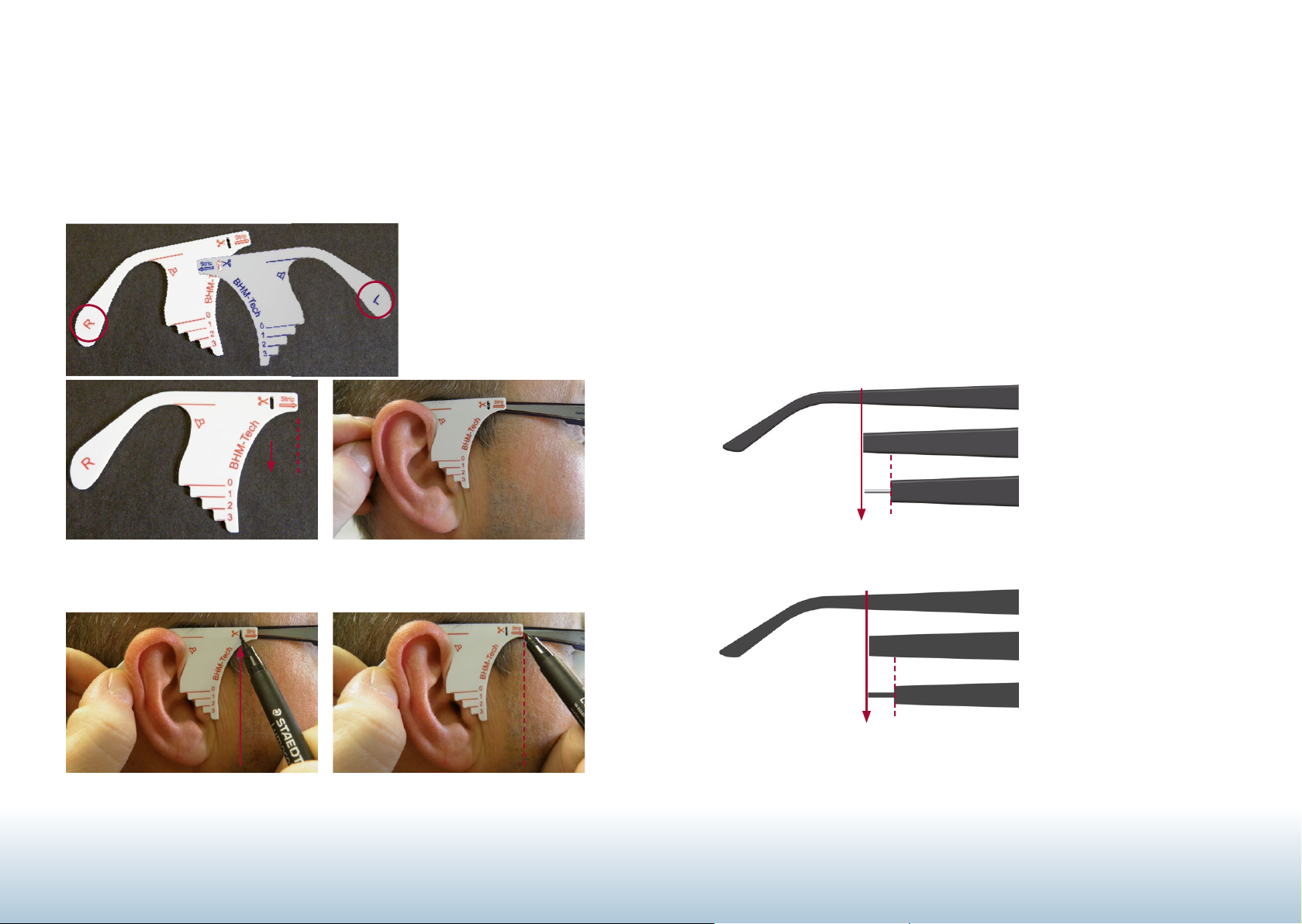
Determining the temple length
Preparation of the temple
To determine the correct temple length, use the fitting template supplied (Fig.1). Ensure the
wearing position of the spectacles is correct.
Use a pen to mark Points A and B by putting the fitting template onto the spectacle
temple (Figs. 3 to 5).
The fitting template is
labelled with letters L (left)
and R (right) for the respective side. (Fig. 1)
Fig. 1
B
A
Fig. 2
A: Cut to length here ( " symbol)
B: Strip plastic
Fig. 3
Put on fitting template
To prepare the temple, remove the temple from the front of the spectacles if required. The
temple is cut to length at marking A using a suitable tool (such as with side-cutting pliers)
and the plastic is stripped to the wire core at marking B (Fig. 6). Then the cut surface has
to be worked with a suitable tool as required (such as a file or sandpaper) - Fig. 6.
Note: When using spectacles with metal temple, this must be cut at marking A using a
suitable tool (such as side-cutting pliers) and be adjusted to the shape of the inner profile
of the adapter at marking B (Fig. 7).
Fig. 6
Plastic temple example:
A: Cut to length temple
B: Strip temple, prepare cut surface
A B
Fig. 7
Metal temple example:
A: Cut to length temple
B: Align to adapter inner profile
Fig. 4
The mark for cutting the temple
to length (A ")
A
Fig. 5
The mark for stripping the plastic
( B Strip Ú )
B
54
A B
Page 4

Cosmetic adjustment of the temple
Mounting the adapter
The temple must be adapted cosmetically to the hearing system by cutting, sanding or
similar such that a smooth transition is created (Fig. 8).
plastic temple
or flat metal temple
Fig. 8
Cosmetic adaptation of plastic or flat metal temple
Clean the protruding wire core with spirit. The glued surface must be free of grease (Fig. 9).
Included with the product is an adapter ring with different adapters suitable for different wire
cores (Fig. 10). Select from them the adapter suitable for your temple.
Fig. 9
Clean the wire core and
remove any grease
1.1 mm
C
0.7 x 2.0 mm
0.9 x 2.0 mm
1.2 mm
1.3 mm
ED
1.1 x 2.0 mm
1.2 x 2.0 mm
1.3 x 2.0 mm
1.4 mm
1.5 mm
C
Fig. 10
C: Adapter for plastic and metal glasses with slimline temples (Ø 1.1 mm)
D: Adapter for plastic and metal glasses with flat wire core (0.7 x 2.0 mm to 1.3 x 2.0 mm)
E: Adapter for plastic and metal glasses with round wire core (Ø 1.2 to Ø 1.5 mm)
76
Page 5
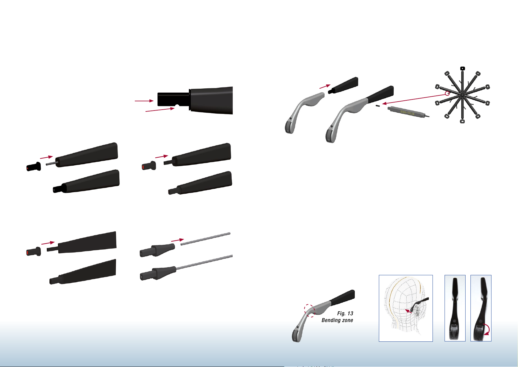
Apply glue to the wire core and the cut surface and fit the adapter onto the temple. Ensure
the adapter sits straight and secure (Fig. 11).
Recommendation: Cyanoacrylate quick-action glue with low viscosity (such as
Loctite 406) Hardening time: approx. 2 minutes.
Fig. 11
Push the adapter onto the temple all the way
The indent must be on the underside when fitting
Plastic temple with round wire core Plastic temple with flat wire core
Mounting the hearing system
Mount the hearing system onto the adapter and secure it using a BHM pin setter and locating
pin (on the adapter ring) - Fig. 12.
Abb. 12
Individual fitting
Individual fitting (Figs. 13 to 15) is possible after adequate warming of the hearing system by
using hot air only on the area specified in Fig. 13 using a frame warmer. The hearing system
may only be heated uniformly in the area stipulated. Please do not use any tools such as
pliers because damage to the plastic material may result.
Flat metal temple Slimline and round metal temple
WARNING: RISK OF BURNS – ENSURE THAT ALL THE PARTS OF THE HEARING SYSTEM HAVE
COOLED BEFORE COMING INTO CONTACT WITH BODY PARTS!!!
CAUTION: When bending the hearing system, never use a naked flame for heating. This can
cause damage to the hearing system. Only the frame warmer with slit nozzle provided may
be used for heating. Max. temperature: 60 degrees Celsius / max. 45 seconds
Fig. 13
Bending zone
Fig. 14
Fig. 15
98
Page 6
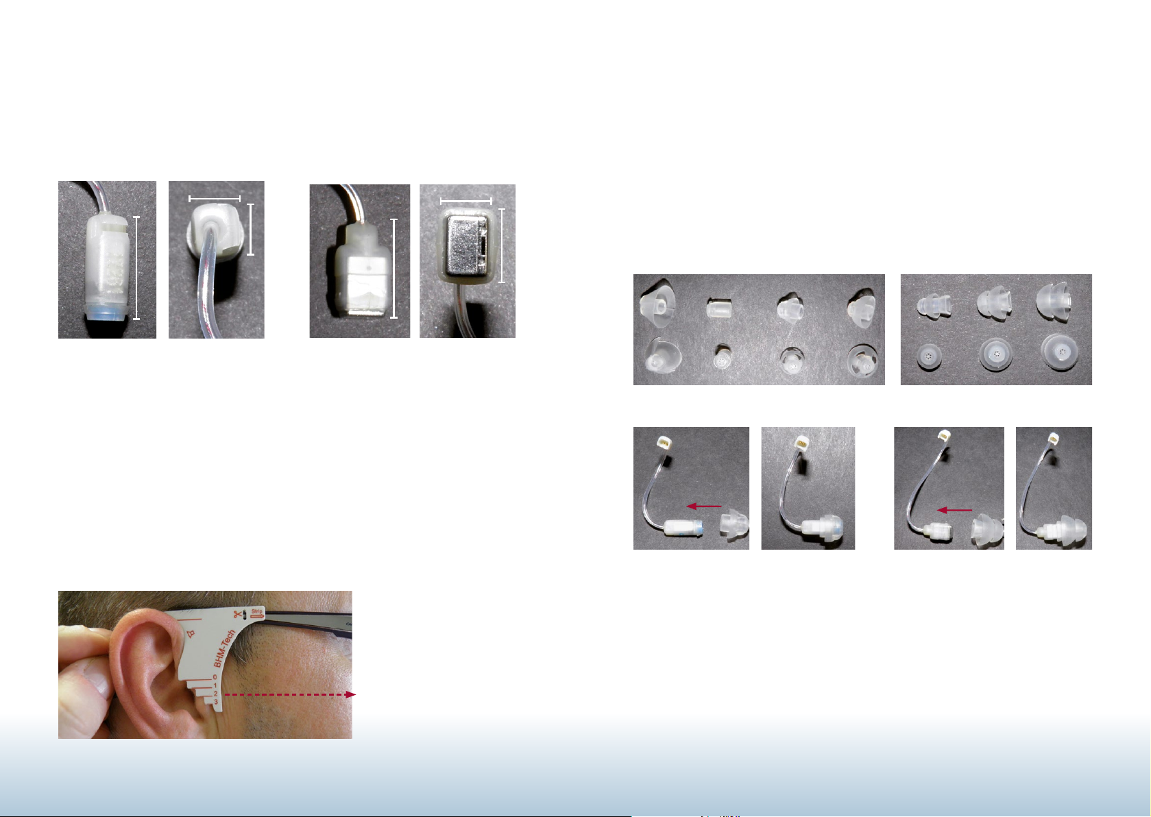
External receiver
Selection and mounting of the earpiece
Use the audiogram, the condition of the auditory canal and the datasheet to decide
whether your customer requires a Normal Power (Fig. 16) or High Power receiver
(Fig. 17).
H
J
G
K
F
Fig. 16
Normal Power receiver
F = 10 mm, G = 3.8 mm, H = 3.6 mm
Fig. 17
High Power receiver
I = 10 mm, J = 4.5 mm, K = 5.5 mm
I
Determining the receiver tube length
At the same time as determining the temple length, the fitting template is used to determine
the correct length of the external receiver tube length, as shown in Fig. 18. Lengths 0, 1, 2
and 3 are available. The value in the centre of the auditory canal is read to determine the
receiver tube length (Fig. 18).
Use the condition of the auditory canal to select the earpiece suitable for your customer
and fit it onto the external receiver (Figs. 21 and 22).
Note there are different earpiece types for Normal Power and High Power receivers
(Figs. 19 and 20).
Fig. 19
Earpieces, Normal Power
Standard SmallSmall MediumMedium LargeLarge
Fig. 21
Example: Normal Power, medium
Fig. 20
Earpieces, High Power
Fig. 22
Example: High Power, medium
Fig. 18
Receiver tube length 2
for example
1110
Page 7
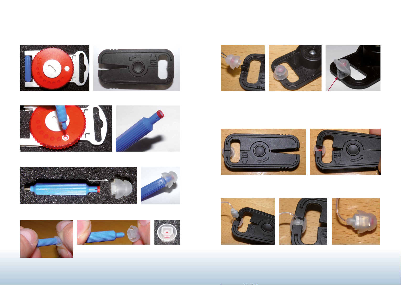
Mounting the High Power earpiece
Cerumen Filter HF3 Mounting tool for High Power earpiece Fit the earpiece over the adapter of the mounting tool.
Removing the HF3 filter
Open the earpiece by pressing together the mounting tool.
Press the HF3 filter as far as it will go into the High Power earpiece.
Ensure that the earpiece is
fully on the mounting tool.
Hold the earpiece and filter at the end and release the
tool from the filter by turning.
Insert the High Power receiver into the open earpiece. Carefully remove the
mounting tool.
1312
Page 8
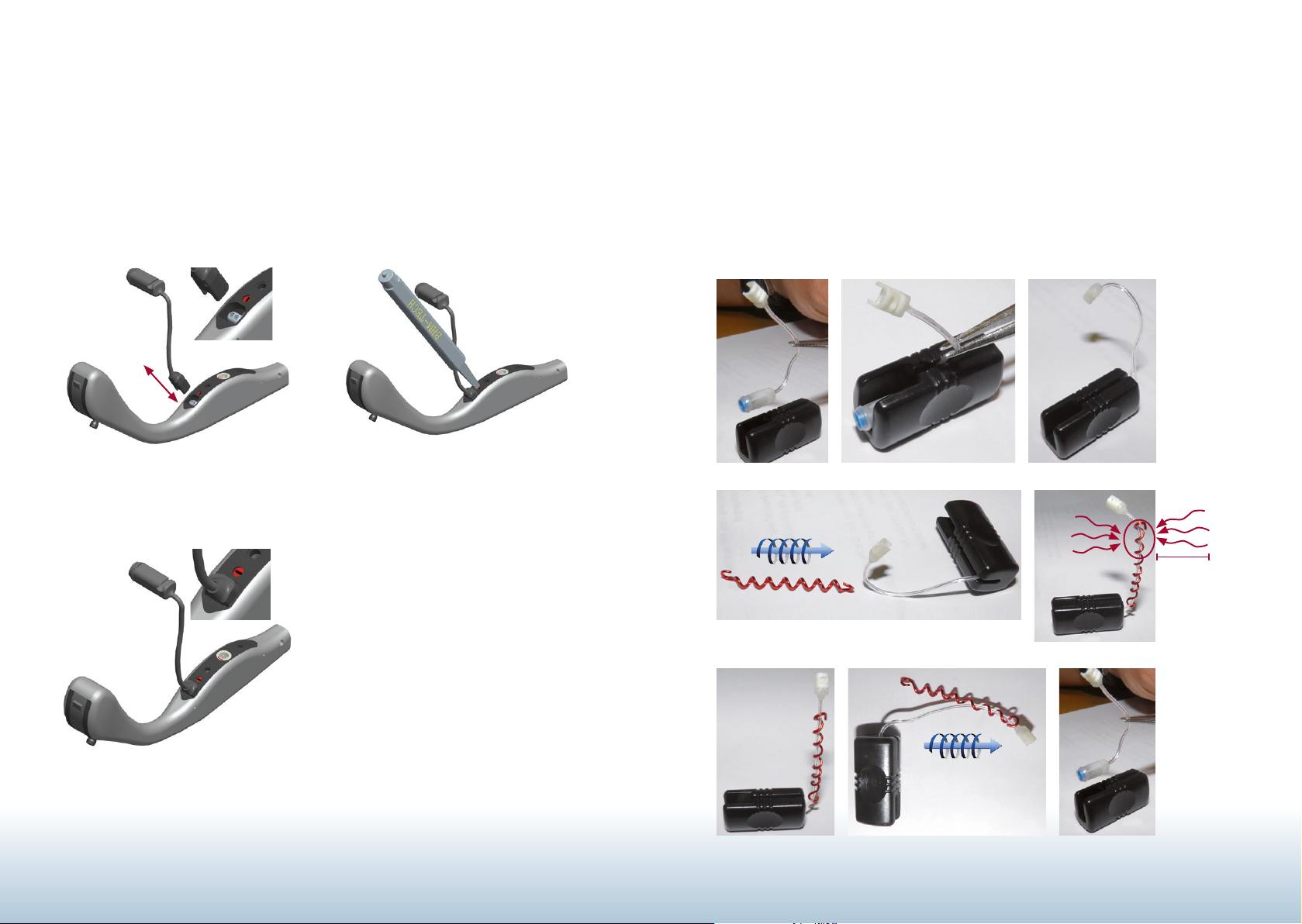
Mounting and dismounting the receiver
See Figs. 23 to 25 for fitting and removing the receiver.
Fig. 24
Fig. 23
1. Receiver lock must be open
2. Open or close the lock with a slotted
screwdriver
Adaptation of the receiver
The tube shape of the receiver can be adapted as follows if required:
Place the receiver into the protective sleeve provided (Fig. 26). Rotate the spiral spring onto
the receiver tube (Fig. 27). Adapt the receiver shape to the customer and heat the receiver
tube using the frame warmer (Fig. 28).
Allow the receiver to cool for at least one minute and remove the spiral spring and protective
sleeve (Fig. 29).
Fig. 26
Fig. 25
3. Receiver lock closed
Note: Unlock 90°clockwise.
Lock 90° anticlockwise.
Remove the receiver
in the reverse sequence!
Fig. 27
15-30 sec.
> 2,5 cm
Fig. 28
Fig. 29
1514
Page 9

Special cases
If the customer has a spectacle frame from Coselgi or BHM-Tech, we offer special adapters
for these (Figs. 30 and 31). When using the pan with these adapters, an overall length as
with existing BHM-Tech and Coselgi hearing temples is attained. This means no subsequent preparation of the existing glasses is necessary.
Fig. 30
COSELGI adapter (left & right)
Connection for programming
Note: No battery needs to be inserted for programming.
Remove the programming socket cover and plug the connector of the programming cable
into the programming socket (Fig. 32).
Note: Ensure that the red marker on the programming cable connector is on the same
side as the marking on the housing (no connection is established otherwise).
Fig. 32
Fig. 31
BHM-Tech adapter (usable left
& right)
Fitting software
To guarantee problem-free function, only use BHM-Tech software approved for this product. Please refer to the „BHMFitpan“ software description for details on the programming
process. Please contact your vendor or BHM-Tech Produktionsgesellschaft mbH if you require clarification.
After the programming process, remove the programming cable and put on the programming
socket cover. If the hearing system is not used for a longer period, keep it in the original
packaging without batteries in a safe place not accessible to anyone unauthorised.
1716
Page 10

Notes
18
Page 11

BHM-Tech Produktionsgesellschaft mbH
Grafenschachen 242
7423 Grafenschachen, Austria
www.bhm-tech.at
According to EU guidelines 93/42/EEC
Quality management system according to DIN EN ISO 134850297
Perfection made in Austria
Responsible for the content: BHM Tech / Design: RABOLD UND CO. / Photos: BHM, Erwin Muik
Version 1.1 - 06/2016
 Loading...