

Page 1
bhi DSP Noise-Canceling
In-Line Module
Reviewed by Paul Danzer, N1II
From the very beginning, radio amateurs have been
trying to pull weak signals out of the accompanying
noise. The designs used depended on the technology
and parts available at the time. As an example, clipping peaks and reducing the bandwidth were initially
all that were available. Later, more sophisticated (and
complicated) circuits were used, such as the current
approach used for some units that sample the noise
alone, usually through a second antenna, so the noise
is captured before it enters the receiver. This noise is
then subtracted from the combined signal and noise
from the main antenna. The expectation is that some,
or hopefully most, noise will be subtracted out.
Another way to reduce, or hopefully eliminate, the
noise is to place an outboard circuit in line with the
audio output of the receiver. The bhi DSP NoiseCanceling In-Line Module is designed to be used this
way — inserted between the receiver audio output and
an external speaker or headphones.
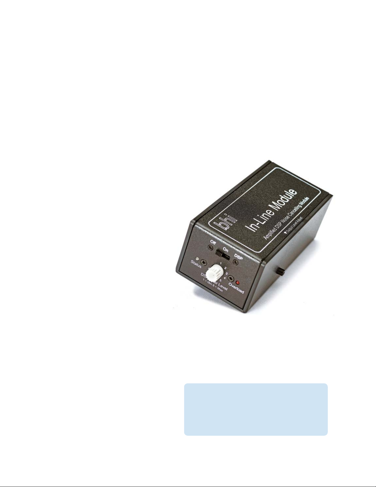
Packaged in an enclosure whose face is approximately
1.82.5 × 5.3 inches (4665135 millimeters), it
occupies very little space on the operating table or
desk (see Figure 5). Today’s availability of complex
integrated circuits results in a weight of approximately
10.6 ounces, excluding interconnecting cables.
Installation Takes Only a Few Minutes
The back of the enclosure has four jacks (see Figure 6).
The white label is a warning that opening the box results
in voiding the warranty. The top left jack accepts a standard 3.5-millimeter monaural plug. Enclosed with the
unit is a cable that has this mating plug on both ends
— one end for the In-Line Module and the other end
for the external speaker output of your receiver. Just
below, on the left, is a 2.1-millimeter barrel connector for
Bottom Line
The bhi DSP Noise-Canceling In-Line Module
works well and is good for noise suppression,
in most cases without distortion on strong
incoming signals.
44 January 2023 QST www.arrl.org
Reprinted with permisison; copyright ARRL.
Page 2
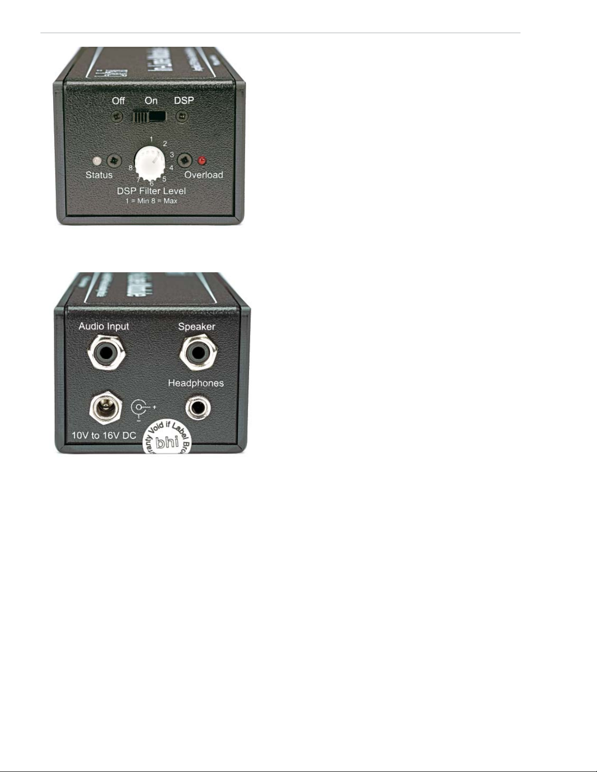
Figure 5 — Only one front panel control, the DSP Filter Level,
might have to be touched during normal operation and then
rarely thereafter.
The controls and LED indicators are on the front panel,
with one more rotary knob on the right side. This knob
controls output volume level.
Control Settings and Indicator Lights
The three-position miniature slide switch on the top of
the panel controls power and processing state. Slid far
left, the unit shuts off and no audio is sent out. In the
center position, indicated as
out but there is no processing. In the far right position,
the
DSP (digital signal processor) circuit is turned on.
The DSP level is controlled by the center rotary switch,
with position
1 the least processing and position 8 the
maximum processing. Noise-canceling levels, corresponding to the switch positions, are speci ed up to
40 dB. Heterodyne tone reduction is speci ed up to
65 dB.
Your selections and the results are echoed by the left
LED (
STATUS) and the right red LED (OVERLOAD). The
STATUS LED goes red when power is applied, and
turns green when the noise cancellation is active.
When the input audio is too high, and the circuit goes
into overload, the right-hand LED goes on. This indicates that you should reduce your receiver audio output
level. The internal 5 W audio ampli er output level is
adjusted by the small knob on the right-hand side of the
enclosure.
ON, ampli ed audio is sent
Figure 6 — Input, output, and power — these are the only
needed connections. You can choose an output to a speaker
or headphones.
10 – 16 V dc to power the unit. A mating cable is
included, with the connector on one end and tinned wire
leads on the other. The monaural speaker jack at the
top right and the headphone jack just below it are also
standard 3.5-millimeter jacks. The power lead includes
a fuse, and dc current requirements are speci ed as
500 mA. There is a warning not to ground any part of
the headphone jack. Four small rubber feet are included
to protect the operating table or desk.
Installation time is, therefore, short. Disconnect your
speaker from your receiver, connect the bhi module to
the receiver speaker jack, and plug your speaker cable
into the unit. Connect the dc lead to your power source,
and you are ready to go.
What’s Inside?
The small instruction book doesn’t provide much
insight into the contents of the module. But you will nd
the details on the manufacturer’s website. Here’s a
summary: The In-Line Module has a powerful programmable DSP audio-processing chip in conjunction with a
10 W mono class D audio power ampli er chip. The
high-performance audio DSP chip delivers exceptional
sound quality and incorporates a full audio signal chain
with 16-bit analog-to-digital (A/D) converters and digital
interfaces to accept the signal through the fully exible
digital processing architecture to analog line level.
Today, a DSP for an audio application usually consists
of an A/D converter on the input, followed by a digital
processor, and nally a digital-to-analog (D/A) converter on the output, most often then feeding a standard audio ampli er. Some DSPs use a generalpurpose microprocessor, while others take advantage
of either chips designed speci cally for DSPs or general-purpose programmable chips. The programming
details of this unit are driven by a set of equations, most
likely proprietary to the manufacturer (bhi) and the
result of extensive testing.
Reprinted with permisison; copyright ARRL.
www.arrl.org QST January 2023 45
Page 3

The 100th edition of The ARRL Handbook for Radio
Communications contains a good deal of information on
DSPs. As faster processing chips (and faster A/D and
D/A converters) became available, more DSPs were
designed and incorporated in amateur radio equipment.
Dave Hershberger, W9GR, is credited as the rst
designer of an audio in/audio out DSP published in an
ARRL publication. It used an early DSP chip. For more
information on DSP designs, see the sidebar, “More
About DSPs.”
On-the-Air Results
A set of tests were run during daylight hours on an
Icom IC-7300 with an LDG tuner and an 80-meter
dipole. On 40 meters there was a Parks on the Air
(POTA) station with an S-8 signal and a background of
S2 – 3 noise. With the slide switch turned to
processing, audio through the unit’s ampli er), the
output volume was the same as it was with the switch
set to
OFF. This indicates that the small volume control
on the right-hand side of the enclosure was set properly. Then with the DSP Filter Level control advanced to
the
2 position, the POTA station popped out of the
noise; alternatively, the noise was well suppressed.
As an experiment, the lter level was advanced to
5 when distortion on the signal was noticeable. Past
that, the signal was too distorted to be usable. The
result was that a setting of
2 was sufficient to suppress
noise in this case.
The POTA station had a lot of activity. For the stations
calling, ranging from S-3 to S-9, the unit was hands-off.
A dial setting of
2 or 3 was good for noise suppression,
in most cases without distortion on strong incoming
signals.
While I was listening to a few other stations, the volume
on the IC-7300 was turned up until the red
OVERLOAD
LED lit. By the time the LED went on, the volume was
louder than you would want in your shack. There also
did not seem to be any difficulty in tuning in a station
with the DSP active. The instruction book warns that in
some cases there will be a slight delay in the received
signal when the unit is switched from
ON to DSP. This
delay did not seem to occur in these tests, but there
was often a delay when switching from
OFF to ON.
During a coincident RTTY contest, the unit was tested
to see if it changed, or perhaps improved, reception or
decoding of a few RTTY signals. No particular effect
was seen.
ON (no
®
4 or
More About DSPs
The 100th edition of The ARRL Handbook for Radio
Communications devotes an entire chapter (Chapter 8)
to DSPs and their functions. Among the examples
included are software-defi ned radios (SDRs). The
chapter begins by pointing out that the mathematical
basis for digital signal processing dates back to wellknown mathematical names in the 17th, 18th, and 19th
centuries. It was not until after the digital revolution in
the early 1990s, with the widespread availability of
digital processing — especially fast processing — that
many applications moved from the theoretical to the
practical. The chapter includes a full page of references and other material. There are also several
online fi les supplementing this chapter.
In the same Handbook edition, Chapter 10, titled
“Analog and Digital Filtering,” contains several sections
devoted to digital fi lter design. This chapter is supplemented by more than a dozen downloadable fi les and
a full page of references and other lists of helpful
materials.
Newer approaches, such as “Deep Learning,” are
also used to design various fi lters. A demonstration
of one such approach is posted by MathWorks at
www.mathworks.com/solutions/deep-learning/
deep-learning-signal-processing.html. They also
off er a free online book on the topic. Other new
approaches can be found under the general topic
“artifi cial intelligence” on the web.
A second set of tests were run in the evening on the
75-meter phone band, with the expectation that the
noise spectrum or other characteristics would be different. The noise level was different, running S-6 to S-7.
There was generally no difference in performance.
A few stations were barely discernable at this higher
noise level. Some could be pulled out by changing the
DSP Filter Level. Other barely discernable signals
popped out of the noise, but they were unintelligible.
At this location, many stations on the 75-meter phone
band tend to have signal strengths of S-9 plus 30 dB;
some of the noise around the weak stations may be
splatter of some sort from one of these strong stations.
Finally, a number of listening tests were run on
20 meters during the day. Results were the same as
on 40 meters. No S-9 plus 30 dB close stations were
encountered on either 40 or 20 meters.
In Summary
The most interesting characteristic noted in these tests
was that on a weekend afternoon, when the POTA contest was very active, operation was primarily hands-off.
46 January 2023 QST www.arrl.org
Reprinted with permisison; copyright ARRL.
Page 4

The DSP Filter Level was set to 2 and left there, except
for a few occasions when the level was turned up just
to see what would happen. However, the noise was
uniform and consistent; there were no thunderstorms
within range. Results might be different with burst noise
sources added into the situation.
Manufacturer: bhi Ltd, 22 Woolven Close, Burgess Hill,
West Sussex RH15 9RR, UK, www.bhi-ltd.com.
Price: $246. Available in the US from several amateur
radio equipment dealers.
Reprinted with permisison; copyright ARRL.
www.arrl.org QST January 2023 47
 Loading...