


L360FS
Instrucciones de montaje y utilización
Instructions for assembly and use

L360FS
INSTRUCCIONES DE SEGURIDAD.-
Rogamos leer estas instrucciones atentamente, antes del montaje y del primer uso. Obtendrá
importantes informaciones para su seguridad, así como para el uso y para el mantenimiento del
aparato de ejercicio.
Guardar cuidadosamente las instrucciones para su información, así como para los trabajos de
mantenimiento o los pedidos de piezas de repuesto.
ATENCIÓN:
Este equipo se debe utilizar solamente para su propósito previsto, es decir para el ejercicio
físico de los adultos.
■ Cualquier otro uso del equipo se prohíbe y puede ser peligroso. El fabricante no se
responsabiliza del daño o lesión causada por el uso incorrecto del equipo.
■ Utilice el equipo sobre una superficie sólida y nivelada.
■ El equipo deberá disponer a su alrededor de un espacio libre no inferior a 0,5 m.
■ El equipo se ha diseñado de acuerdo con lo más último en los estándares de seguridad.
■ Este equipo esta conforme con el estándar EN 957. Adecuado para uso profesional, con un
peso máximo del usuario 150kg.
■ Las reparaciones incorrectas y/o las modificaciones estructurales del equipo (Ejemplo: Retirar
o el reemplazar piezas, no originales) pueden poner en peligro la seguridad del usuario.
■ Los componentes dañados pueden poner en peligro su seguridad y/o reducir curso de la vida
del equipo.
Por esta razón, las piezas dañadas se deben sustituir inmediatamente y el equipo mantenerlo
fuera de uso hasta que se haya reparado. Utilice solamente el repuesto original de piezas BH.
■ El si el equipo está en uso regular, comprobar todos sus componentes a fondo cada 1 ó 2
meses, prestando atención muy particular al reapriete de tuercas y tornillos.
■ Antes de comenzar su programa del ejercicio, consulte a su doctor para asegurarse de que
puede utilizar el equipo.
Base su programa del ejercicio en el consejo dado por su doctor o preparador físico.
Los ejercicios incorrectos o excesivos pueden dañar su salud. Trabaje en el nivel de ejercicio
recomendado, no llegue al agotamiento.
■ Preste por favor mucha atención a las indicaciones del manual del entrenamiento.
Para la realización del montaje de este equipo, son necesarios dos personas al menos,
como le muestran las figuras adjuntas de este manual de instrucciones.

SAFETY INSTRUCTIONS
Please read these instructions carefully before assembling and using the equipment. They
contain important information for your safety and for the use and maintenance of the exercise
equipment.
Keep the instructions safe for future reference and maintenance tasks as well as for ordering
spare parts.
ATENTION:
■ This equipment must only be used for its intended purpose, i.e. physical exercise.
■ Any other use of the equipment is prohibited and may be dangerous. The manufacturer is not
responsible for damage or injury caused by misuse of the equipment.
■ Use the equipment on a solid level surface.
■ The equipment must have at least 0.5 metres of free space around it.
■ The equipment is designed in accordance with the latest safety standards.
■ This equipment complies with standard EN 957. Suitable for professional use, with a
maximum user weight of 150kg.
■ Incorrect repairs and/or structural modifications to the equipment (E.g.: Removal of parts or
non-original replacement parts) can endanger the user’s safety.
■ Damaged components may endanger your safety and/or reduce the useful life of the
equipment.
For this reason, damaged parts must be replaced immediately and the equipment taken out of
use until it is repaired. Use only original BH spare parts.
■ If the equipment is in regular use, check all components thoroughly every 1 or 2 months,
paying particular attention to retightening nuts and bolts.
■ Before beginning your exercise program, consult your doctor to make sure that you can use
your exercise equipment.
Base your exercise program on the advice given by your doctor or trainer.
Incorrect or excessive exercise can damage your health. Work at the recommended exercise
level, do not overexert yourself.
■ Pay close attention to the trainer's exercise instructions.
It is necessary at least, the assistance of a second person when assembling this
machine, as shown in the diagrams that accompany this instruction manual.

Saque la unidad de la caja, compruebe e identifique las piezas con respecto al listado de la Fig.A y Fig.B,
para asegurarse de que no falta ninguna pieza, para el montaje del equipo, en la primera fase.
Take the unit out of its box, check and identify the parts against the list in Fig.A and Fig.B to ensure that
there are no missing parts for the initial assembly stage of the equipment.
Fig.A
Nº
Nº
1
2
2R
1
2L
1
3
1
4
1
5
1
6
1
7
1

8
1
9
2
10
2
11
2
13
1
14
1
15
1
16
1

17
1
20
4
21
2
28
1
29
2
30
1

31
1
32
1
34
8
36
2
38
5
39
4
40
6
41
7

42
8
43
4
44
8
48
1
81
7

9
Fig.B
Nº
83
M-8x100
2 84
M-10x30
2
89
M-10x75
8 90
M-10x80
38
92
M-10x100
1 93
M-10x105
6
97
M-10x25
2 99
M-12x70
1
105
M-8x8
16 106
M-8
4
107
M-10
108
108
M-12
1
116
M-8
2 117
M-10
53
118
M-12
1 126
Hex Key
S=3/16”
1
127
Hex Key
S=4
1 128
Hex Key
S=6
1
129
Hex Key
S=8
1
NOTA: La descripción de las piezas con respecto a las figuras, corresponden siempre
a la posición de la persona en el equipo para la realización del ejercicio.
NOTE:
The description of the parts with respect to the figures always corresponds to
the position the person adopts on the equipment when exercising.

10
Fig.1
INSTRUCCIONES DE MONTAJE.-
Apoye en el suelo el soporte principal (5).
Coloque en las barras laterales (1), (2R), (2L) los tacos de apoyo (40) y atorníllelos con los tornillos junto
con las arandelas y las tuercas suministrados en los tacos (40).
Coloque en las barras laterales (1), (2R), (2L) las pletinas (38), la polea superior (17) y los soportes
barra (21) y atorníllelos con los tornillos (90) junto con las arandelas (107) y tuercas (117) tal como se
muestra en la figura 1 al soporte inferior (5) y al soporte superior (4).
INSTRUCTIONS FOR ASSEMBLY.-
Rest on the floor the main support (5). Place in lateral bars (1), (2R), (2L) the adjusting pads (40) and
tighten the screws with washers and nuts provided inside the pads (40).Place the lateral bars (1), (2R),
(2L) the plates (38), the upper pulley (17) and the fixed frames (21) and tighten the screws (90) with
washers (107) and nuts (117) as shown in Fig 1 to the main support (5) and upper support (4).

11
Fig.2
Atornille el soporte brazos (3) al soporte superior (5) atorníllelos con los tornillos (89) junto con las
arandelas (107) y tuercas (117) manteniendo la posición tal como se muestra en la figura 1.
Tighten the arm support (3) to the upper support (5) with screws (89), washers (107) and nuts (117)
maintaining the position as shown in Fig 1.

12
Fig.3
Sitúe el tope de pesas (42) en la torre de pesas, introduzca las barras de pesas (34).
A continuación coloque las pesas (130); (131); (132), siempre las de mayor peso en la parte inferior, por
ultimo coloque la pesa de guía con su barra selectora (39), atornille las barras de pesas por la parte
superior con las arandelas (44) y los tornillos (105). Coloque la anilla del selector (43), en el casquillo
central de la pesa guía (39).
Realice el mismo montaje para los otros tres lados.
Place the weight stop (42) on the weight stack, insert the weight guide bars (34). Then place the weights
provided (130); (131); (132) the heavier weights always at the bottom. Finally fit the guide weight with the
selector bar (39), tighten the top of weight guide bars using washers (44) and screws (105).
Fit the selector ring (43) into the central bushing on the weight guide (39). Now go through the same
procedure for the other three sides.

13
Fig.4
Coloque en el soporte del banco remo (6) el taco de apoyo (40) y atorníllelo con el tornillo junto con la
arandela y la tuerca incluida en el taco (40). Coloque el soporte (8) sobre las barras (1) y atorníllelo con
los tornillos (90) junto con las arandelas (107) y las tuercas (117).
Acerque el soporte del banco remo (6) hasta hacer coincidir con el soporte (8). Atornillar el soporte
banco remo (6) al soporte (8) con los tornillos (90) junto con las arandelas (107) y las tuercas (117) y al
soporte principal (5) con los tornillos (93) junto con las arandelas (107) y las tuercas (117).
Place the adjusting pad (40) in the rower support (6) and screw with the screw, washer and nut included
in the pad (40).
Place the bracket (8) on the bars (1) and tighten with the screws (90) along the washers (107) and nuts
(117).
Bring the rower support (6) to join with the support (8). Tighten the rower support (6) to the support (8)
with screws (90) along washers (107) and nuts (117) and the main support (5) with screws (93), washers
(107) and nuts (117).

14
Fig.5
Coloque la placa metálica (32) sobre el soporte banco remo (6) y atornille con los tornillos (97) y apriete
fuertemente. Coloque el soporte reposapiés (7) sobre el soporte banco remo (6) y atornille con los
tornillos (84) y arandelas (107) y apriete fuertemente.
Coloque los soporte de polea (36) en el soporte del banco remo tal y como indica la figura 5 y fíjelos con
los tornillos (83) junto con las arandelas (106) y las tuercas (116) y apriete fuertemente.
Place the fixed plate (32) on the rower support (6) and with the screws (97) tighten securely. Place the
footrest bracket (7) on the rower support (6) and with the screws (84) and washers (107) tighten
securely.
Place the double pulley brackets (36) in the rower support bracket as shown in Fig 5, and secure with
screws (83) with washers (106) and nuts (116) and tighten securely.
15
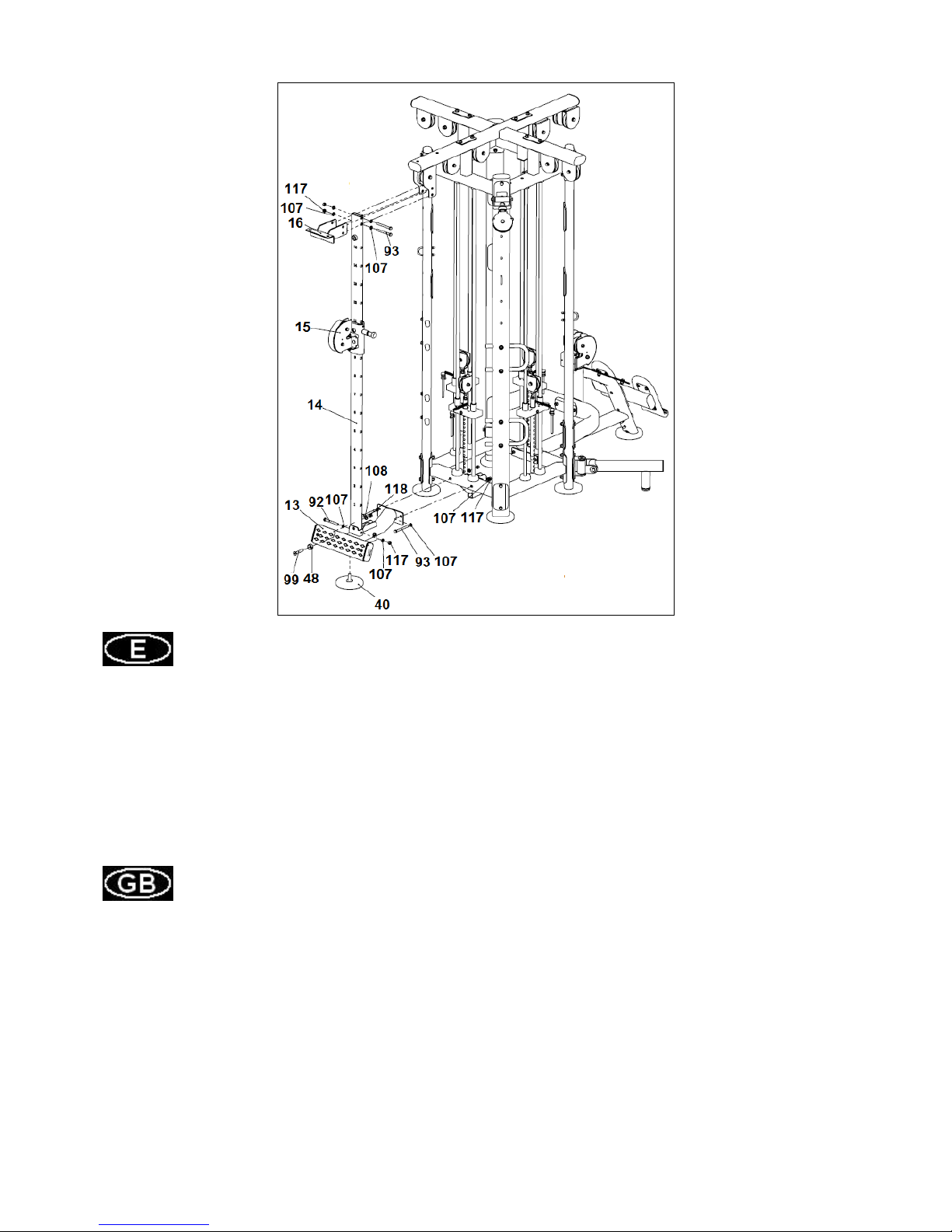
Fig.6
Coloque en el soporte (13) el taco de apoyo (40) y fíjelo con el tornillo junto con la arandela y la tuerca
suministrado en el taco (40).
Introduzca en el mástil de posiciones (14) el selector de posiciones (15) tal y como muestra la fig. 6.
Posicione el mástil de posiciones (14) en la “U” del soporte inferior (13), atorníllelo a las “U” con los
tornillos (92) y (93) y el taco (118) y arandela (108) y con las arandelas (107) y las tuercas (117) como
se indica en la figura 6.
Posicione el mástil de posiciones (14) junto con el soporte inferior en el bastidor principal (5). Atorníllelo
en la parte superior junto con la pletina (16) al soporte (4) con los tornillos (93) junto con las arandelas
(107) y las tuercas (117) y al bastidor principal (5) según la figura 6.
Place the adjusting pad (40) in the support (13) and screw with the screw, washer and nut included in
the pad (40).
Insert in the adjusting tube (14) the selector frame (15) as shown in Fig. 6. Position the adjusting tube
(14) in the "U" rear frame (13), screw the "U" with screws (92) and (93), nylon nut (118), washer (108),
washers (107) and nuts (117) as shown in Figure 6. Place the adjusting tube (14) with the rear brake
(13) on the main frame (5). Fit on the top along with the plate (16) to the upper support (4) with screws
(93), washers (107) and nuts (117) and to the main frame (5) according to Fig 6.

16
Fig.7
Coloque el soporte inferior del brazo Buttlerfly (10) en los brazos laterales (2L) y (1) como indica la
figura 7. Atorníllelo con los tornillos (90) junto con las arandelas (107) y las tuercas (117).
Una vez apretado coloque el eje del brazo Butterfly (11) en el soporte (10) e introduzca el eje superior
del brazo Buttlerfly en el soporte (9). Fije el soporte (9) a los brazos laterales (2L) y (1) como indica la
figura 7. Atorníllelo con los tornillos (90) junto con las arandelas (107) y las tuercas (117).
Realice el mismo montaje descrito anteriormente con el brazo derecho (11R).
Place the lower support arm Buttlerfly (10) in the side arms (2L) and (1) as shown in Figure 7. Screw the
screws (90) with washers (107) and nuts (117). A tight time place the Butterfly arm shaft (11) in the
bracket (10) and enter the upper arm shaft Buttlerfly on the support (9). Attach the support (9) to the side
arms (2L) and (1) as shown in Figure 7. Screw the screws (90) with washers (107) and nuts (117).
Perform the same setup described above with the right arm (11R).

17
Fig.8
Coja el cable (30) y enebre el cable en las poleas (A) y (B) que se encuentra en el soporte poleas (3) y
en la polea (C) hasta los soportes poleas (36) tal y como se muestra en la figura 8.
Coja los enganche de cadenas (81) y una los extremos del cable (30) con los tensores y únalos al asa
(41) como muestra la figura 8.
Take the cable and thread the cable on pulleys (A) and (B) located in the pulley bracket (3) and through
the pulley (C) to the double pulley bracket (36) as shown in fig 8.
Take the chain hook (81) and join the end of cable (30), which you have just threaded through, with the
cable tensioner and join to the handle (41). Fig.8.

18
Fig.9
Sujete el extremo del cable (28) a la tuerca tensora de cables como se indica en la figura 9.
Coja el otro extremo del cable (28) y siguiendo las flechas indicadas en el cable páselos por las poleas
indicadas como (D), (E), (F), (G), (H), (I).
Seguido pase la punta del cable (28) por la polea (J),
Coja el enganche de cadenas (81) y una el extremo del cable (28) con el tensor y únalo al asa (41)
como muestra la figura 9.
Attach the end of the cable (28) to the cable tensioning nut as shown in Figure 9. Take the other end of
the cable (28) and looking the arrows shown thread it through the pulley marked as (D), (E), (F), (G), (H),
(I). Then thread the end of the cable (28) through the pulley (28). Take the chain hook (81) and join the
end of cable (28), which you have just threaded through, with the cable tensioner and join to the handle
(41). Fig.9.

19
Fig.10
Sujete el extremo del cable (29) a la tuerca tensora de cables como se indica en la figura.
Coja el otro extremo del cable (29) y enebre el cable en las poleas (K), (L), (M), (N) y (O) como muestra
la figura.
Coja el enganche de cadenas (81) y una el extremo del cable (29) con el tensor y únalo al asa (41)
como muestra la figura 10.
Realice el mismo montaje para el cable del brazo Butterfly (11R), descrito anteriormente.
Attach the end of the cable (29) to the cable tensioning nut as shown in figure 10. Take the other end of
the cable (29) and looking the arrows shown thread it through the pulley marked as (K), (L), (M), (N) and
(O). Take the chain hook (81) and join the end of cable (29), which you have just threaded through, with
the cable tensioner and join to the handle (41). Fig.10.
Perform the same setup described above with the Butterfly arm cable (11R).

20
Fig.11
Por último enebre el cable (31) en la polea (17) tal y como se muestra en la figura 11.
Coja los enganche de cadenas (81) y una los extremos del cable (31) con los tensores y únalos al asa
(41) como muestra la figura 11.
Finally thread the cable (31) on pulleys (17) and (B) as shown in fig 11.
Take the chain hook (81) and join the end of cable (31), which you have just threaded through, with the
cable tensioner and join to the handle (41). Fig.11.
MUY IMPORTANTE:
Una vez realizado el montaje, compruebe que todos los tornillos que han sido montados en esta
maquina, están fuertemente apretados.
VERY IMPORTANT:
After assembling the unit, check that all of the screws have been fitted to the machine and that
they are tightened securely.

L360FS

Para pedido de repuesto: Indicar el código de la pieza y la cantidad.
To order replacement parts: State the part code and Quantity.
Nº
Code Nº
Code Nº
Code Nº
Code
1 A-L360FSK0100 33 A-L360FSK3500 65
A-BNH0528 97
A-CNLM10*25DS20
2 A-L360FSK0200 34 A-L360FSK3600 66
A-L1-6800 98
A-CNLM12*60DS20
3 A-L360FSK0300 35
A-IZ70120200 67
A-IZ70051000 99
A-CNLM12*70DS20
4 A-L360FSK0400 36
A-IT9325G1500 68
A-IT9315G1500 100
A-PNLM6*12DS20
5 A-L360FSK0500 37
A-HG51200 69 A-IN-D20021000 101
A-PNLM8*15DS20
6 A-L360FSK0600 38
A-AXT3S0302 70
A-IZ70120400 102
A-PNLM10*25DS20
7 A-L360FSK0700 39
A-IT93021900 71
A-M01004800 103
A-PNLM10*40DS20
8 A-L360FSK0800 40
A-IT93201800 72
A-SG500110400 104 A-YLS0.5*13*95DS20
9 A-L360FSK0900 41 A-CWRVL0021600 73
A-MFT-7002700 105
A-GB77M8*8DS18
10 A-L360FSK1000 42
A-IT80023000 74
A-IT90302303 106
A-GB958DS2
11 A-L360FSK1100 43
A-IE95191400 75 A-IN-D20020802 107
A-GB9510DS2
12 A-L360FSK1200 44
A-IT93252800 76 A-HF900-03A1002 108
A-GB9512DS2
13 A-L360FSK1300 45
A-IZ70010600 77
A-KFFT0700 109
A-DQ10DS2B
14 A-L360FSK1400 46
A-IT90013800 78
A-GB30151104 110
A-DQ10DS2D
15 A-L360FSK1500 47
A-IT80101800 79 A-GB27661804-2Z 111
A-DQ16DS2
16 A-L360FSK1600 48 A-CMJ61752100 80 A-GB2766005-2Z 112 A-YDQ13.5*27*2DS2
17 A-L360FSK1700 49
A-KPSFID3000 81
A-HLG8DS2 113
A-GB938DS12
18 A-L360FSK1800 50
A-BNH0514 82
A-BNH0718 114
A-GB9310DS12
19 A-L360FSK1900 51
A-BNH0533 83
A-
GB5780M8*100DS20
115
A-GB41M6
20 A-L360FSK2000 52 A-IT80261500V1 84
A-
GB5780M10*30DS2NL
116
A-NM8DS2
21 A-L360FSK2100 53 A-TCS130WS4700 85
A-
GB5780M10*30DS20
117
A-NM10DS2
22 A-L360FSK2200 54
A-SL70013200 86
A-
GB5780M10*40DS20
118
A-NM12DS2
23 A-L360FSK2500 55
A-FS544600 87
A-
GB5780M10*50DS20
119
A-NM16DS2
24 A-L360FSK2600 56
A-TPF-533000 88
A-
GB5780M10*55DS20
120
A-GB923M8DS2
25 A-L360FSK2700 57
A-HV66700 89
A-
GB5780M10*75DS20
121 A-YNM0.313*18*8DS2

26 A-L360FSK2800 58 A-IN-B72011700 90
A-
GB5780M10*80DS20
122
A-YNM0.5*13*8DS2
27 A-L360FSK2900 59
A-KL22019500 91
A-
GB5780M10*95DS20
123
A-GB894.125DS12
28 A-L360FSK3000 60
A-TBT12100 92
A-
GB5780M10*100DS20
124
A-
GB17880.5M8*16.5DCS17
29 A-L360FSK3100 61
A-IT9008B3800 93
A-
GB5780M10*105DS20
125
A-LHφ6.8*1DS2
30 A-L360FSK3200 62 A-HVCORE5400 94
A-
GB5780M10*115DS20
130
A-IT80033200ST
31 A-L360FSK3300 63
A-M02502000 95
A-
GB5780M10*120DS20
131
A-IT80033300ST
32 A-L360FSK3400 64
A-HF985A1800 96 A-CNLM8*20DS20 132
A-IT80124400ST

BH HIPOWER SPAIN
EXERCYCLE,S.L. (Manufacturer)
P.O.BOX 195
01080 VITORIA (SPAIN)
Tel.: +34 945 29 02 58
Fax: +34 945 29 00 49
e-mail: hipower@bhfitness.com
www.bhfitness.com
POST-VENTA
Tel: +34 945 292 012 /
902 170 258
Fax: +34 945 56 05 27
e-mail: hipower@bhfitness.com
BH HIPOWER NORTH AMERICA
20155 Ellipse
Foothill Ranch
CA 92610
Tel: + 1 949 206 0330
Toll free: +1 866 325 2339
Fax: +1 949 206 0013
e-mail:
fitness@bhnorthamerica.com
www.bhnorthamerica.com
BH HIPOWER ASIA
No.139, Jhongshan Rd.
Daya Township
Taichung 428, Taiwan. R.O.C.
Tel.: +886 4 25609200
Fax: +886 4 25609280
e-mail: info@bhasia.com.tw
BH HIPOWER PORTUGAL
MAQUINASPORT, APARELHOS
DE DESPORTO, S.A.
Rua do Caminho Branco Lote
8, ZI Oiã 3770-068 Oiã
Oliveira do Bairro (PORTUGAL)
Tel.: +351 234 729 510
Fax: +351 234 729 519
e-mail: info@bhfitness.pt
BH SERVICE PORTUGAL
Tel.: +351 234 729 510
Fax: +351 234 729 519
e-mail: info@bhfitness.pt
BH HIPOWER MEXICO
BH Exercycle de México S.A.
de CV
Eje 132 / 136
Zona Industrial, 2A Secc.
78395 San Luis Potosí
S:L:P: MÉXICO
Tel.: +52 (444) 824 00 29
Fax: +52 (444) 824 00 31
www.bh.com.mx
BH HIPOWER CHINA
BH China Co., Ltd.
Block A, NO.68, Branch Lane
455, Lane 822,
Zhen Nan RD., Li Zi Yuan,
Putuo, Shanghai 200331,
P.R.C.
Tel: +86-021-5284 6694
Fax:+86-021-5284 6814
e-mail: info@i-bh.cn
BH HIPOWER UK
Tel: 02037347554
e-mail:
sales.uk@bhfitness.com
AFTER SALES – UK
Tel.: 02074425525
e-mail:
service.uk@bhfitness.com
BH HIPOWER FRANCE
SAV FRANCE
Tel : +33 0810 000 301
Fax : +33 0810 000 290
savfrance@bhfitness.com
BH Germany GmbH
Altendorfer Str. 526
45355 Essen
Tel: +49 201 450910-0
e-mail: info@bhgermany.com
Kostenfreie Telefonnummer:
0800 0996655
Ersatzteile:
www.bhfitness.com
BH SE RESERVA EL DERECHO A MODIFICAR LAS ESPECIFICACIONES DE SUS PRODUCTOS SIN PREVIO
AVISO.
SPECIFICATIONS MAY BE CHANGED WITHOUT PRIOR NOTICE DUE TO OUR PROGRAMME OF
CONTINUOUS PRODUCT DEVELOPMENT.
BH SE RÉSERVE LE DROIT DE MODIFIER LES SPECIFICATIONS DE SES PRODUITS SANS PRÉAVIS.
BH BEHALT SICH DAS RECHT VOR, ÄNDERUNGEN DER MODELL-ANGABEN OHRE VORHERIGE
ANKÜNDIGUNG VORZUNEHMEN.
DATI TECNICI E COMMERCIALI RELATIVI AGLI ARTICOLI DEL PRESENTE CATALOGO POSSONO ESSERE
SOGGETIL A VARIAZIONI SENZA ALGUN PREAVVISO.
BH SE RESERVA O DIREITO A MODIFICAÇÀO ESPECIFICAÇOES DOS SEUS PRODUCTOS SEM PRÉVIO
AVISO.
DOOR KONSTANTE PRODUKTVERNIEUWING EN VERBETERING HOUDEN WIJ ONS HET RECHT VAN
WIJZIGING VOOR ZONDER VOORAFGAAND BERICHT.
v1
 Loading...