

BGW 85 Owner's Manual
13130
SOUTH
YUKON
AV~NUE
HAWTHORNE,
CAL-JFORNJA
90250
PHONE
(213)
973-8090
TEL-EX NO,
66-4494
.,
"'
OWNER'S MANUAL
MODEL 85
BROADCAST POWER AMPLIFIER
TABLE
OF
CONTENTS
DESCRIPTION
FORM NUMBER
,"
Important
• .
· 00601
Description
• • • • •
· 00831
Option
Page
• •
• 00835
Specifications
• • 00940
Unpacking and
Set-Up
•
. . . . . . .
02510
Rack
Mounting
Hints
. .
. . . . . . .
02650
Input
Connections.
•
• 03060
Output
Connections.
•
• • 03520
Speaker
Fuse
Nomagraph.
03530
Damping
Factor
Nomagraph
03510
Stereo
Headphone
Connections
• .
03590
Mono
Operation.
• . . . •
03680
Power Mains
Connection
.
04000
Opera
tion . . . . . . .
05200
f ' :
Circuit
Description
• • . • • • • • .
. . 06265
Schematic
Diagram,
Amplifier
• • •
15720
Schematic
Diagram,
Power
Supply. 15730
Chassis
Interconnection
Wiring • . . • . . .
1574-0
Option
-06/07
Transformer
Input
Connections.
.
1574-1
Option -01
Active
Input
Connections.
1574-2
Block
Diagram
• . . . . . . . . .
15710
Parts
List . • • . . . . 15790
Product/Option
Matrix.
16000
Warranty 17000
Service
Authorization
Form
17020
Warranty
Registration
Form
.
17030
OUb<J!-!
-
IMPORTANT-
PLEASE. READ THIS PAGE BEFORE OPERATING
YOUR
BGW
POWER AMPLIFIER
Your new
BGW
amplifier
is
designed to provide
years
of
trouble
free
performance.
Observing
these
few
precautions
will
insure
proper
operation:
Read all
Instructions
before
connecting
any
AC power
to
your power
amplifier.
Retain
this
Manual
for
future
reference.
Heed all warnings on
the
top
or
rear
of
the
power
amplifier.
The
amplifier
should
not
be used
near
water -for
example,
near a bathtub,
washbowl,
kitchen
sink, laundry tub, in a
wet
basement,
or
near
a swimming pool,
etc.
The
amplifier
should be
situated
so
that
its
location
or position does
not
interfere
with
its
proper
ventilation.
For
example,
it
should
not
be
situated
on a bed,
sofa,
rug, or
similar
surface
that
may
block
the
ventilation
openings;
or,
placed
in a
built-in
installation,
such
as
a bookcase or
cabinet
that
may
impede
the
flow of
air
through
the
ventilation
openings.
The
amplifier
should be
situated
away
from
heat
sources
such
as
radiators,
heat
registers,
stoves,
or
other
appliances
that
pr.oduce
heat.
The
amplifier
should be
connected
to
a power supply only of
the
type
described
in
the
operating
instructions
or
as
marked
on
the
rear
panel.
Precautions
should be
taken
so
that
the
grounding
means
of
the
amplifier
is
not
defeated.
The power supply
cord
should be
routed
so
that
it
is not
likely
to
be walked on or
pinched by
items
placed
upon or
against
it,
paying
particular
attention
to
cord
at
the
plug,
convenience
receptacles,
and
the
point
where
they
exit
from
the
amplifier.
Care
should be
taken
so
that
objects
do
not
fall into, and liquids
are
not spilled into
the
amplifier
through
openings.
00601-2
'!he
amplifier
should
be
serviced
by
qualified
sezvice
personnel
when:
'!he
IXMer
supply
cord
or
the
plug
has
been
damaged;
or
abj
acts
have
fallen
into,
or
liquid
has
been
spilled
into
the
amplifier:
or
has
been
exposed
to
rain;
or
does
not
~
to
operate
normally
or
exhibits
a marked c.hange
in
perfo:cnance;
or
has
been
dropped,
or
the
enclosure
has
been
damaged.
All
connections
should
be
made
to
the
power
amplifier
with
the
power OFF.
Speaker
fuses
should
be
used
to
afford
maxilm.un
speaker
protection.
Never
connect
the
rut:put
of
one
channel
to
that
of
another.
Connect
the
IXM9r
cord
to
the
proper
voltage
mains
as
in:li.cata:1. CI'l
tie
rear
of
the
amplifier.
Conversion
to
arxXharvolta;)e
req..rires
intemal
~.
I):)
not
rencve
the
amplifier's
cover.
Amplifiers
may
not
be
covered
\.ll'Der
warranty
if
they
are
tanpered
with.
'!here
are
NO
adjustments
within.
Potentially
lethal
voltages
exist
within
the
amplifier.
Iefer
all
se:rvicE
YJOrk
to
an
authorized
EGi
sern.ce
station.
DESCRIPTION
The
BGW
Model 85 is one
of
the
most
advanced
solid
state,
full
complementary,
bridgeable,
stereo
power
amplifiers
available.
Features
of
the
Model 85 include
Magnetic
Circuit
Breaker/Power
Switch,
Input
Level
Controls,
Headphone
Jack,
and
Power
Indicator,
~"
input
connectors,
separate
circuit
and
chassis
grounds, and
small
size.
The
Front
Panel
includes
two
Input
Level
Controls,
Power
Switch,
Headphone
Jack,
and Green LED
Power
Indica
tor.
The
Rear
Panel
includes
AC Input
Cord,
two
Yt.
Phone
Jack
Input
Connectors,
Mono/Stereo Switch
to
convert
amplifier
to
a fully
bridged
Mono
amplifier
and
a 6
point
screw
terminal
strip
for
the
output
of
each
amplifier
and
ground
circuits.
Both
the
circuit
and chassis grounds
are
connected
to
separate
barrier
strip
terminals
on
the
rear
of
the
amplifier.
They
are
connected
together
by a
removeable
link.
By
removing
the
link,
the
circuit
grounds
of
all
active
units
(amplifiers,
preamplifiers,
mixers,
etc.)
can
be
tied
to
earth
ground
at a common
point.
This aids
in
eliminating
ground loops.
The
size
of
the
Model 85 is
convenient
for a wide
variety
of
applications.
However,
please
note
the
following
precautions:
1)
Do
not
use
the
front
panel
as
the
sole
support
for
the
amplifier.
Side rails
or
rack
shelves
should
be
employed.
2)
Do
not
stack
Model 85
amplifiers. A minimum
of 1
3/4
inches
above
each
amplifier
should be provided for
free
air
circulation.
The
output
voltage
follower
stage
of
your
amplifier
uses
the
most
advanced
type
of
transistors
available.
These
large
geometry,
150
watt
complementary
power
devices
have
large
safe
operating
areas
and
extended
power
bandwidth.
Electrostatic
and
other
highly
reactive
speaker
systems
present
no
difficulties
for
the
Model 85.
All of
the
semiconductors
in
the
output
area
are
in
intimate
contact
with
the
heat
sink. The bias
stage
is
mounted
on
the
same
heat
sink
as
the
output
transistors
and
provide
temperature
compensated
bias
current
to
the
output
stage.
The input
stage
utilizes
NPN
matched
low noise
transistors
connected
as
a
differential
pair.
This
stage
drives
two common
emitter
voltage
stages
in
Push
Pull. The
output
of
the
voltage
amplifier
stage
is loaded
by a current
mirror
stage,
bias
stage
and
the
complementry
Darlington
output
stage.
The Model 85
is
wired for use
at
120
VAC
only
I
...."
J
The-
ampUfler should
be
serviced
by
qualWed
service
personnel when:
nr
I'
The
power
supply
card
.
or
the
plug
has
been
damaged;
or
objects have
fallen
intc~
or
Uquici ·hu
been
spilled
1ntD
me
amplifier;
or
has
been
expcsed
to
rain;
or
aces
no't
appear
to
oper&'te normally
or
extUbit:s a
marked c:hange in
perlcrmance;
or
has
been
drop~
«
the
enc:icsure has
been
damqed.
All
camectioas
shoWci
be
made
to
the
power
amplifler
with
the
power
OFF.
Speaker fuses should
be
'4sed
to
affCX"d
maximum speaker pro'teeCon.
Neve"
ecnnec:t
Ute
output
at ene d1annei
to
that
at another.
Connect
the
pow
..
=rd
to
the
proper
voltage
mains
as
indicated
on
the
rear
ot
the
amplWer. Convenicn
to
anather
voltage
requires
in'tem&L
rewiring.
00
nC't remove Ute
amplifiers
=ver.
Amplifiers
may no't be covered under
warnnty
if
they
are
tampered
.
with.
There are NO adjustments
within.
Potentially
lethal
voltages
exist
within
the
amplifier.
Reter
all
service
work
to
an authorized
SGW
service
staticn.
'
00835
OPTIONS
FOR
'mE
r-DDEL
85
'!he
Model
85
may
be
ordered
with
the
follor.ori.rq
options:
85-01
Dlal
C1"lannel
Active
Balanced
Inputs
(with
70
dB
omR)
85-06
Dlal
Cllannel
Transfonner
Balanced
Inputs
85-20
XIR
Unbalanced
Inputs
THE
BGW
85
BROADCAST POWER
AM
PLIFIER
Exacting
design
standards
and unique
features
establish
the
BGW
amplifier
as
the
industry
leader
in
power
amplifier
technology.
Features
such
as
all
steel
chassis
and
covers,
metal-case
output
transistors,
totally
modular
construction
and
large
alumimum
heat-sink
have
set
the
industry
standard
in audio
power
amplifiers.
Delivering
at
least
35
watts
per
channel
into
8 ohm loads and using
the
latest
in
full
complementary
circuitry
techniques,
the
Model 85
offers
reliability
and
performance
unparalleled
in
the
industry.
SPECIFICATIONS:
BGW
MODEL 85
OUTPUT POWER
35
watts
minimum
sine
wave
continuous
average
power
output
per
channel
with
both
channels
driving 8-ohm loads
over a power
band
from
20tfz
to
20kHz. The
maximum
Total
Harmonic
Distortion
at
any power
level
from
250-milliwatts
to
25
watts
shall
be
no
more
than
.05% from 20Hz
to
5kHz
then
rising
linearly
to
a
maximum
of
.10%
at
20kHz.
45
watts
minimum
sine
wave
continuous
average
power
output
per
channel
with
both
channels
driving 4-ohm loads
over a power
band
from
20Hz
to
20kHz. The
maximum
Total
Harmonic
Distortion
at
any power
level
from
250-milliwatts
to
45
watts
shall
be
no
more
than
.10% from 20Hz
to
5kHz
then
rising
linearly
to
a
maximum
of
.20%
at
20kHz.
90
watts
minimum
sine
wave
continuous
average
power
output
monaural
driving an
8-ohm load
over a power
band from 20Hz
to
20kHz. The
maximum
Total
Harmonic
Distortion
at
any
power
level
from
250-milliwatts
to
90
watts
shall
be
no
more
than
.10%
from
20Hz
to
5kHz
then
rising
linearly
to a maximum
of
.20%
at
20kHz.
*"
All
specifications
and
features
are
subject
to
change
without
notice.
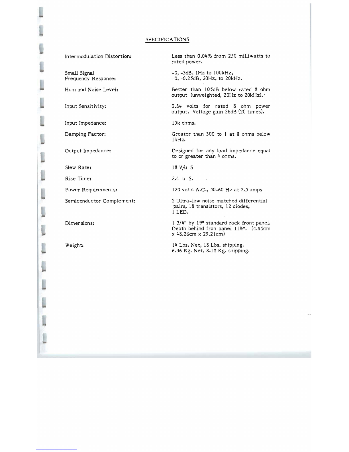
Intermodula
tion
Distortion:
Small Signal
Frequency
Response:
Hum and Noise Level:
Input
Sensitivity:
Input
Impedance:
Damping
Factor:
Output
Impedance:
Slew
Rate:
Rise
Time:
Power
Requirements:
Semiconductor
Complement:
Dimensions:
Weight:
SPECIFICATIONS
Less
than
0.04%
from
250
milliwatts
to
rated
power.
+0, -3dB, 1Hz
to
100kHz,
+0, -0.25dB, 20Hz,
to
20kHz.
Better
than
105dB below
rated
8 ohm
output
(unweighted,
20Hz
to
20kHz).'
0.84
volts
for
rated
8 ohm
power
output.
Voltage gain 26dB (20
times).
15k ohms.
Greater
than
300 to 1
at
8 ohms below
1kHz.
Designed for any
load
impedance
equal
to
or
greater
than 4 ohms.
18
V/u
S
2.4 u S.
120 volts
A.C.,
50-60
Hz
at
2.5
amps
2
Ultra-low
noise
matched
differential
pairs,
18
transistors,
12
diodes,
1 LED.
1 3/4" by 19"
standard
rack
front
panel.
Depth
behind fron
panel
11Y2".
(4.45cm
x 48.26cm x 29.21cm)
14
Lbs.
Net,
18
Lbs. shipping.
6.36 Kg.
Net,
8.18 Kg. shipping.
02'10
UNPACKING AND SET-UP
Your
BGW
Power Amplifier is shipped in an advanced packing
container.
SA
VE
THE CONT AINER
AND ALL PACKING MATERIAL!
The
container
should be saved in
the
event
the
unit is moved or shipped
at
some
future
date.
Replacement
containers
are
available
from
BGW
Systems.
Inspect
the
unit for
damage
in
transit
immediately
upon
receipt.
If
damage
is
found,
notify
the
transportation
company
immediately.
Only
the
consignee
may
institute a claim
with
the
carrier
for shipping
damage.
BGW
will
cooperate
fully in
such an
event.
Be
sure
to
save
the
container
as
evidence
of
damage
for
the
shipper
to
inspect.
The
amplifier's
mounting position
must
be
chosen
carefully,
so
that
the
air
flow
around
the
unit is
not
restricted.
Inadequate
ventilation
may
cause
failure
of
the
amplifier.
For
rack
mounting,
the
four rubber
feet
on
the
bottom
of
the
unit
may
be removed and no
hardware
wiJ1
be loosened inside
the
unit.
The
size
of
the
amplifier
is
convenient
for a wide
variety
of
applications.
However, please
note
the
following
precautions:
1.) Do not use
the
front
panel
as
the
sole
support
for
the
amplifier.
Side
ralls or
rack
shelves should be
employed.
2.)
Do
not
stack
amplifiers.
A minimum of 1 3/4" above
each
amplifier
should be provided for
free
air
circulation.
DO NOT PLUG THE AMPLIFIER
IN
YET!
AU
connections should be made
before
power is
applied.
RACK MOUNTING HINTS
KEEPING
IT
COOL
A power
amplifier
draws
energy
from a primary
electrical
?ervice,
usually a
l20
VAC
outlet,
to
drive
loudspeaker
systems
with an audio
signal.
Typically,
only
half
of
the
energy
can
be
delivered
to
the
loudspeakers;
remaining
energy
is
converted
into
heat,
and
must
be
dissipated
(ventilated)
into
the
air.
Air
circulating
past
heat-producing
components
absorbs
the
heat
and
carries
it
away. To
accomplish
this,
low and
medium
power
amplifiers
rely
on
natural
convection
currents,
while
most high power
amplifiers
use
fans.
If
the
air
flow
is
impeded,
the
resulting
rise
in
heat
may
cause
an
amplifier
to
stop
working or
fail.
Circulating
air
currents
must
not
be
cut
off
when
installing
power
amplifiers
in
racks.
Power
amplifiers
using
convection
cooling
require
spacing
between
amplifiers
to
permit
air
flow
between
them.
Power
amplifiers
using
forced-air
cooling,
on
the
other
hand,
can
usually be
stacked
closer
to
each
other
and
may
not
need
any blank panel
spacing
between
amplifiers.
To
improve
natural
convection
currents
within a
rack, a chimney
can
be
created
by
closing
the
back
of
the
rack
and
venting
the
rack
at
the
bottom
to
let
in
fresh
air,
and
at
the
top
to
exhaust
hot
air.
Vents should be
large
rectangular
slots
approximately
19"
wide by
4"
high.
The
rack
cabinet
will
require
some
type
of blower if a
large
air-flow
is
required.
It
is
best
to
exhaust
air
from
the
top
of
the
rack
rather
than
to
blow
it
in
from
the
bottom.
There
will be less dust and
dirt
in
the
rack
this
way, if
the
bottom
vent
is
sufficiently
large.
INST ALLING THE UNITS
Use
care
when
mounting
equipment
in a
rack.
Place
the
heaviest
units
near
the
bottom
of
the
rack
and fill in
all
unused
rack
spaces
with
blank
panels.
Equipment
cannot
always be
supported
by
front
panels
alone.
This is
especially
true
of
amplifiers
whose
depth
is
more
than
twice
their
height.
Uniform
support
can
be
insured
by
installing
bottom
or side
rails.
When racks
are
to
be
transported
or used in a
mobile
installation,
some
means
of
securing
the
rear
of
the
equipment
are
required.
Angle
brackets
either
attached
to
the
bottom,
side
rails
or
rear
panel
are
practical
approaches.
03060
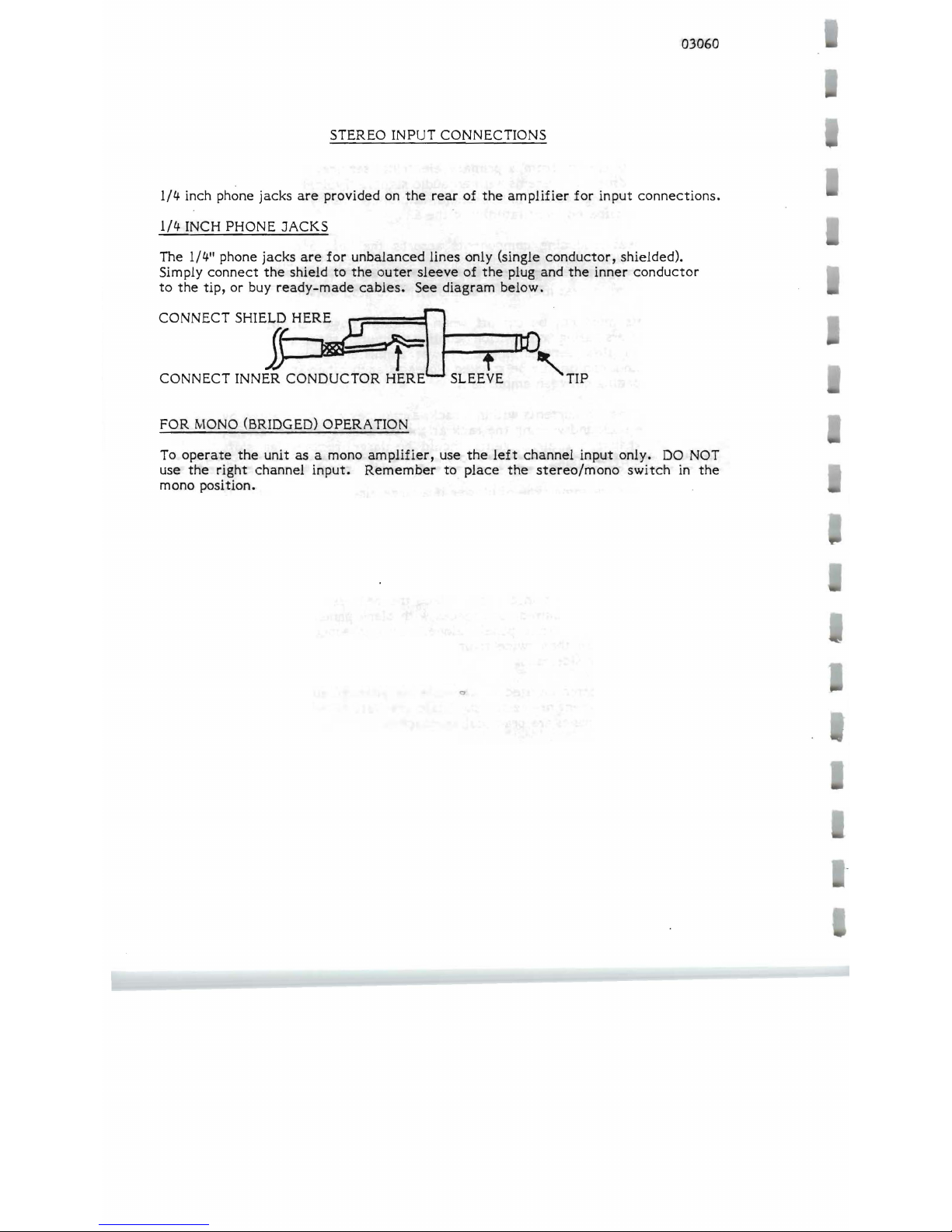
STEREO INPUT CONNECTIONS
1/4 inch phone jacks
are
provided on
the
rear
of
the
amplifier
for
input
connections.
1/4 INCH PHONE JACKS
The 1/4" phone
jacks
are
for
unbalanced
lines only (single
conductor,
shielded).
Simply
connect
the
shield to
the
outer
sleeve
of
the
plug and
the
inner
conductor
to
the
tip, or buy
ready-made
cables.
See diagram
below.
CONNECT
SHI]
HE~
=t1J-_-r---
1
t1)
CONNECT INNER CONDUCTOR HERE
SLEEtE
'TIP
FOR
MONO
(BRIDGED) OPERA TrON
To
operate
the
unit
as
a mono
amplifier,
use
the
left
channel
input
only.
DO
NOT
use
the
right
channel
input.
Remember
to
place
the
stereo/mono
switch
in
the
mono position.
..,
03520
STEREO OUTPUT CONNECTIONS
A six
(6)
station
screw
barrier
block on
the
rear
panel,
serves
as
output
connectors,
with
one plus (+)
and
one minus (-)
for
each
channel.
Left
Channel
leads
go
to
barrier
stations
marked
LEFT;
right
channel,
to
those
marked
RIGHT.
Output
leads
are
best
connected
to
the
amplifier
with
the
use of
tinned
wires.
Make
certain
that
the
speakers
are
properly
phased.
Connect
the
black
or minus (-)
terminal
on
the
speaker
cabinet
to
t!:1e
appropriate
minus (-)
barrier
on
the
amplifier.
Connect
the
red
or
plus (+)
terminal
to
the
plus (+)
barrier.
Check
to
see
that
the
stereo-mono
switch
on
the
rear
of
the
amplifier
is in
the
stereo
position.
SPEAKER PROTECTION
All
speakers
can
be
damaged
by having too much power
applied
to
them.
Fuse
protection
is
an
effective
and inexpensive
way
of
preventing
this
from
occurring.
If
your
speaker
system
does
not
contain a fuse
or a
circuit breaker, a fuse
should
be
placed
in
series
with
each
speaker
and
the
wire
going
to
the
red
terminal
on
the
rear
of
the
am plif
ier
.
Maximum
protection
can
be
obtained
with
fast-acting
fuses.
Use
the
value
recommended
by
the
manufacturer.
If
no
value
is
specified,
use
the
chart
provided
to
select
the
correct
value.
(MFRM 03530)
To
use
the
chart,
take a straightedge,
such
as a ruler,
and
line
up
the
speaker's
impedance
with
its
peak
music
power
rating.
The
proper
fuse
value
can
then
be
read from
the
center
column.
Choose a
fuse
that
is
closest
to,
and
below,
the
value
indicated.
WIRE SIZE AND DAMPING FACTOR
The high damping
factor
of
BGW
amplifiers
results
in a very
dean
bass
response.
Excessively long, and
small
diameter
speaker
wires
can
lower
the
damping
factor
and
distort
the
lower
frequencies.
A
damping
factor
of
at
least
50
should be
maintained
to
insure good audio
quality.
The
relationship
between
wire
length
and
diameter,
and
damping
factor
can
be
calculated
using
the
chart
(MFRM 03510) on
the
following
page.
Proceed
as
follows:
1.
Using a
straight-edge,
line
up
the
gauge of
the
speaker
wire
with
its
length.
Mark
off
the
resul
ting
source
resistance
where
this
line
crosses
the
center
column.
2. Line
up
the
source
resistance,
determined
in
step
Ill,
with
the
manufacturer's
impedance*
of
the
speaker
system.
The
damping
factor
can
now be
read.
*The
impedance
of a
speaker
system
can
be
approximated
by
measuring
the
resistance
across
the
speaker
terminals,
with
the
amplifier
disconnected.
Multiplying this
result
by 1.33, gives you
the
approximate
impedance.
Note:
This
method
cannot
be used with
electrostatic
speakers.
 Loading...