

BGH BSBSM24CMO, BSBSM72CTO, BSBSM36CTO, BSBSM60CTO Installation & User Manual
Installation & User Manual
Middle Static Pressure Duct Type
Air Conditioner
Modelos:
BSBSM24CMO, BSBSM36CTO, BSBSM60CTO, BSBSM72CTO
Important note:
Read this manual carefully before installing or operating your new air conditioning unit. Make sure
to save this manual for future reference.

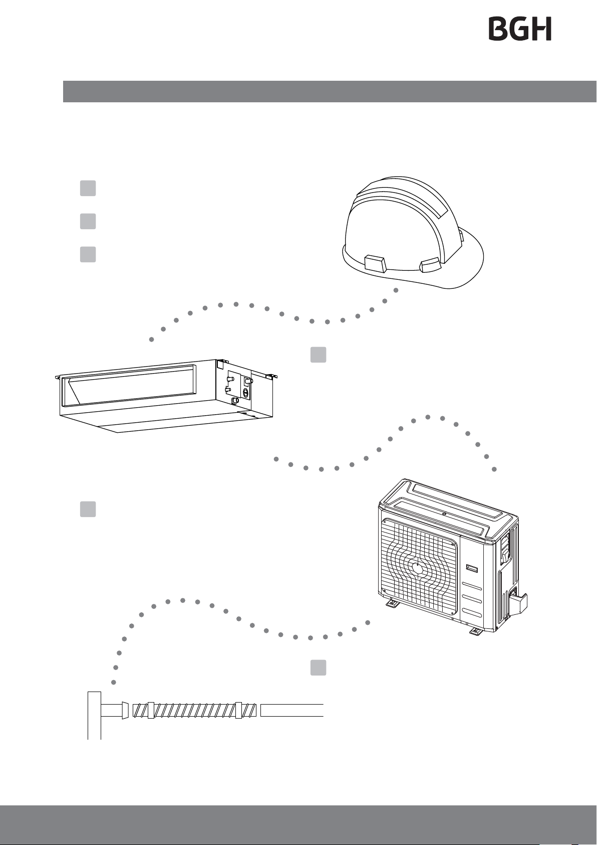
Table of Contents
Installation Manual
1
Accessories ....................................................05
2
Safety Precautions .....................................06
3
Installation Overview ............................... 07
5
Outdoor Unit Installation ......................... 13
a. Outdoor Unit Installation Instructions ......13
b. Outdoor Unit Types and Specifications ....14
c. Notes on Drilling Hole in Wall ....................15
4
Indoor Unit Installation
a. Indoor Unit Parts ........................................ 08
b. Indoor Unit Installation Instructions .......09
........................... 08
6
Drainpipe Installation ...............................16
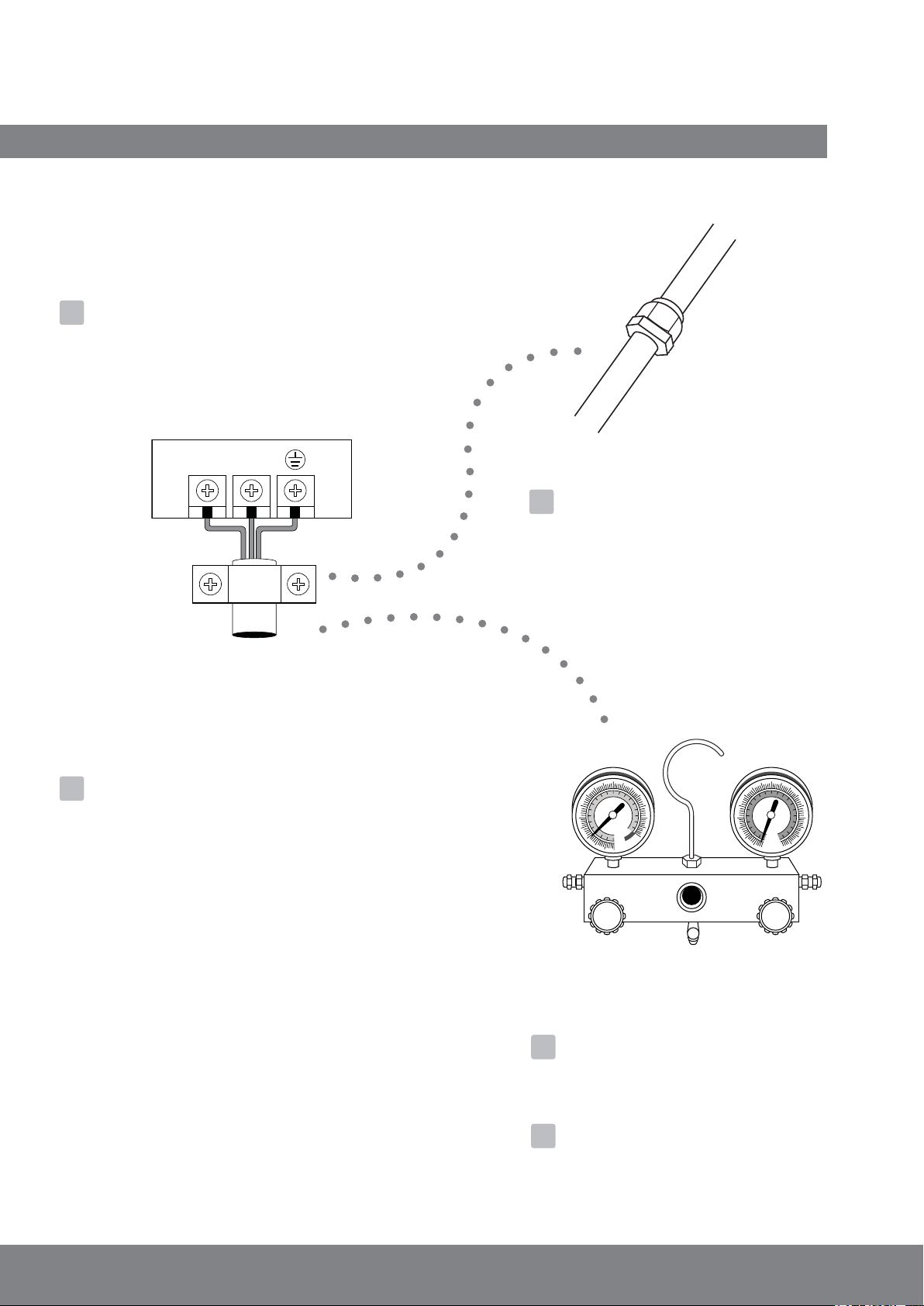
Refrigerant Piping Connection .......................18
7
A. Notes on Pipe Length and Elevation ..............18
B. Refrigerant Piping Connection Instructions ...20
L N
8
Wiring ................................................. 23
a. Outdoor Unit Wiring .................. 23
b. Indoor Unit Wiring ..................... 24
c. Power Specifications ................... 26
9
Air Evacuation ..................................................28
a. Evacuation Instructions ................................ 28
b. Note on Adding Refrigerant ....................... 29
MC MC
10
Test Run ............................................. 30
11
Impedance Information 31
.............
Page 3
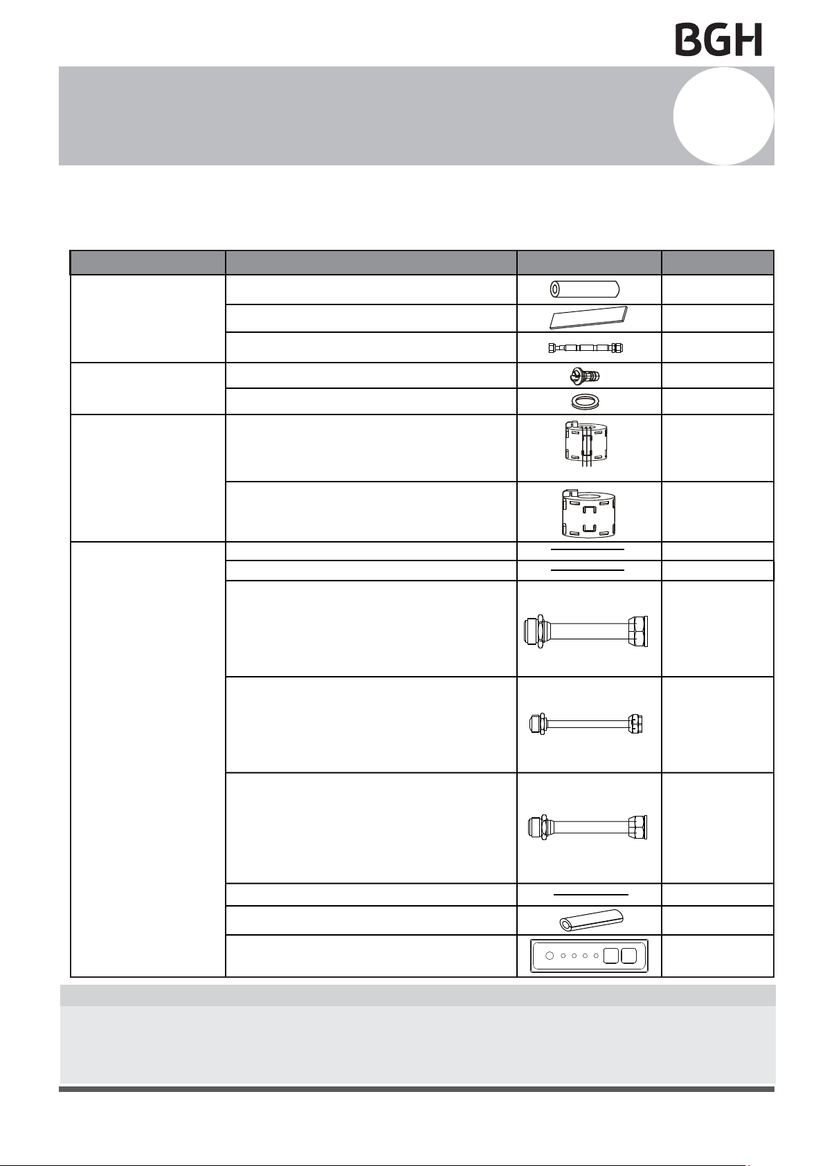
Accessories
1
The air conditioning system comes with the following accessories. Use all of the installation parts
and accessories to install the air conditioner. Improper installation may result in water leakage,
electrical shock and fire, or equipment failure.
Tubing & Fittings
Drainpipe Fittings
(for cooling & heating)
EMC Magnetic Ring
(some models)
Others
Soundproof / insulation sheath
Seal sponge (some models)
Orifice (some models)
Drain joint (some models)
Seal ring (some models)
Magnetic ring
(wrap the electric wires S1 & S2 ( P & Q & E )
around the magnetic ring twice)
Magnetic ring
(Hitch on the connective cable between the indoor
unit and outdoor unit after installation.)
Owner‘s manual
Installation manual
Transfer connector(Φ12.7-Φ15.9)/
Φ0.5in-Φ0.63in
( )(Packed with the indoor unit )
NOTE: Pipe size may differ from appliance to
appliance. To meet different pipe size requirements,
sometimes the pipe connections need a transfer
connector installed on the outdoor unit .
Transfer connector(Φ6.35-Φ9.52)/
( )(Packed with the indoor unit)
Φ0.25in-Φ0.375in
NOTE: Pipe size may differ from appliance to
appliance. To meet different pipe size requirements,
sometimes the pipe connections need a transfer
connector installed on the outdoor unit .
Transfer connector(Φ9.52-Φ12.7)/
Φ0.375in-Φ0.5in
( ) (Packed with the indoor unit,
used for multi-type models only )
NOTE: Pipe size may differ from appliance to
appliance. To meet different pipe size requirements,
sometimes the pipe connections need a transfer
connector installed on the outdoor unit .
Connecting wire for display (2m)
Cord protection rubber ring
SHAPENAME
S1&S2(P&Q&E)
QUANTITY
2
1
1
1
1
1
1
1
1
1
(on some models)
1
(on some models)
1
(on some models)
1(on some models)
1(on some models)
Display panel
*Just for testing purposes only
1(on some modelsKJR-120G,KJR-120H)
Optional accessories
•
There are two types of remote controls: wired and wireless.
Select a remote controller based on customer preferences and requirements and install in an
appropriate place.
Refer to catalogues and technical literature for guidance on selecting a suitable remote controller.
Page 5
Safety Precautions
Failure to observe a caution may result in injury or equipment damage.
2
Read Safety Precautions Before Installation
Incorrect installation due to ignoring instructions can cause serious damage or injury.
The seriousness of potential damage or injuries is classified as either a WARNING or CAUTION.
Failure to observe a warning may result in death. The product must be installed by
WARNING
CAUTION
WARNING
installers or contractors who are licensed HVAC professionals and in compliance with
all local, state and provincial laws.
• Carefully read the Safety Precautions before installation.
• In certain functional environments, such as kitchens, server rooms, etc., the use of specially
designed air-conditioning units is highly recommended.
• Only trained and certified technicians should install, repair and service this air
conditioning unit.
Improper installation may result in electrical shock, short circuit, leaks, fire or other damage to
the equipment and personal property.
• Strictly follow the installation instructions set forth in this manual.
Improper installation may result in electrical shock, short circuit, leaks, fire or other damage to
the equipment.
• Before you install the unit, consider strong winds, typhoons and earthquakes that might affect
your unit and locate it accordingly. Failure to do so could cause the equipment to fail.
• After installation, ensure there are no refrigerant leaks and that the unit is operating properly.
Refrigerant is both toxic and flammable and poses a serious health and safety risk.
Note about Fluorinated Gases
This air-conditioning unit contains fluorinated gases. For specific information on the type of gas
1.
and the amount, please refer to the relevant label on the unit itself.
2.
Installation, service, maintenance and repair of this unit must be performed by a certified
technician.
Product uninstallation and recycling must be performed by a certified technician.
3.
4.
If the system has a leak-detection system installed, it must be checked for leaks at least every 12
months.
5.
When the unit is checked for leaks, proper record-keeping of all checks is strongly recommended.
Page 6
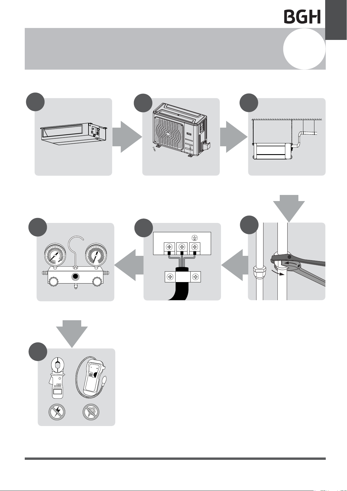
Installation Overview
L N
INSTALLATION ORDER
Unit Installation
Overview
3
1
Install the indoor unit
(Page 8)
6
MC MC
2
Install the outdoor unit
(Page 13)
5
3
Install the drainpipe
(Page 15)
4
Evacuate the refrigeration system
(Page 28)
7
Perform a test run
(Page 30)
Connect the wires
(Page 23)
Connect the refrigerant pipes
(Page 18)
Page 7

Indoor Unit
Installation
Indoor Unit Parts
Indoor Unit Installation
4
Air inlet
Electric control cabinet
Air filter(on selected models)
Air outlet
Fig. 4.1
Safety Precautions
WARNING
• Securely install the indoor unit on a structure
that can sustain its weight. If the structure is
too weak, the unit may fall causing personal
injury, unit and property damage, or even
death
• DO NOT install the indoor unit in a bathroom
or laundry room as excessive moisture can
short the unit and corrode the wiring.
Indoor Unit Installation Instructions
Step 1: Select installation location
The indoor unit should be installed in a location
that meets the following requirements:
√
Enough room for installation and maintenance.
√
Enough room for the connecting pipe and
drainpipe.
√
The ceiling is horizontal and its structure can
sustain the weight of the indoor unit.
√
The air inlet and outlet are not impeded.
√
The airflow can fill the entire room.
√
There is no direct radiation from heaters.
√
It is embeded installation.
√
Models with a cooling capacity of 9000Btu to
18000Btu only apply to one room.
Drain hose
Refrigerant connecting pipe
CAUTION
• Install the indoor and outdoor units, cables
and wires at least 1m (3.2’) from televisions
or radios to prevent static or image
distortion. Depending on the appliances, a
1m (3.2’) distance may not be sufficient.
• If the indoor unit is installed on a metal
part of the building, it must be grounded.
CAUTION
DO NOT install the unit in the following
locations:
Where oil drilling or fracking is taking place.
Coastal areas with high salt content in the air
Near geothermal activity and corrosive gas
Buildings that may experience power
Enclosed spaces
Areas with strong electromagnetic waves
Areas that store flammable materials or gas
Rooms with high humidity, such as
fluctuations
bathrooms or laundry rooms
Page 8
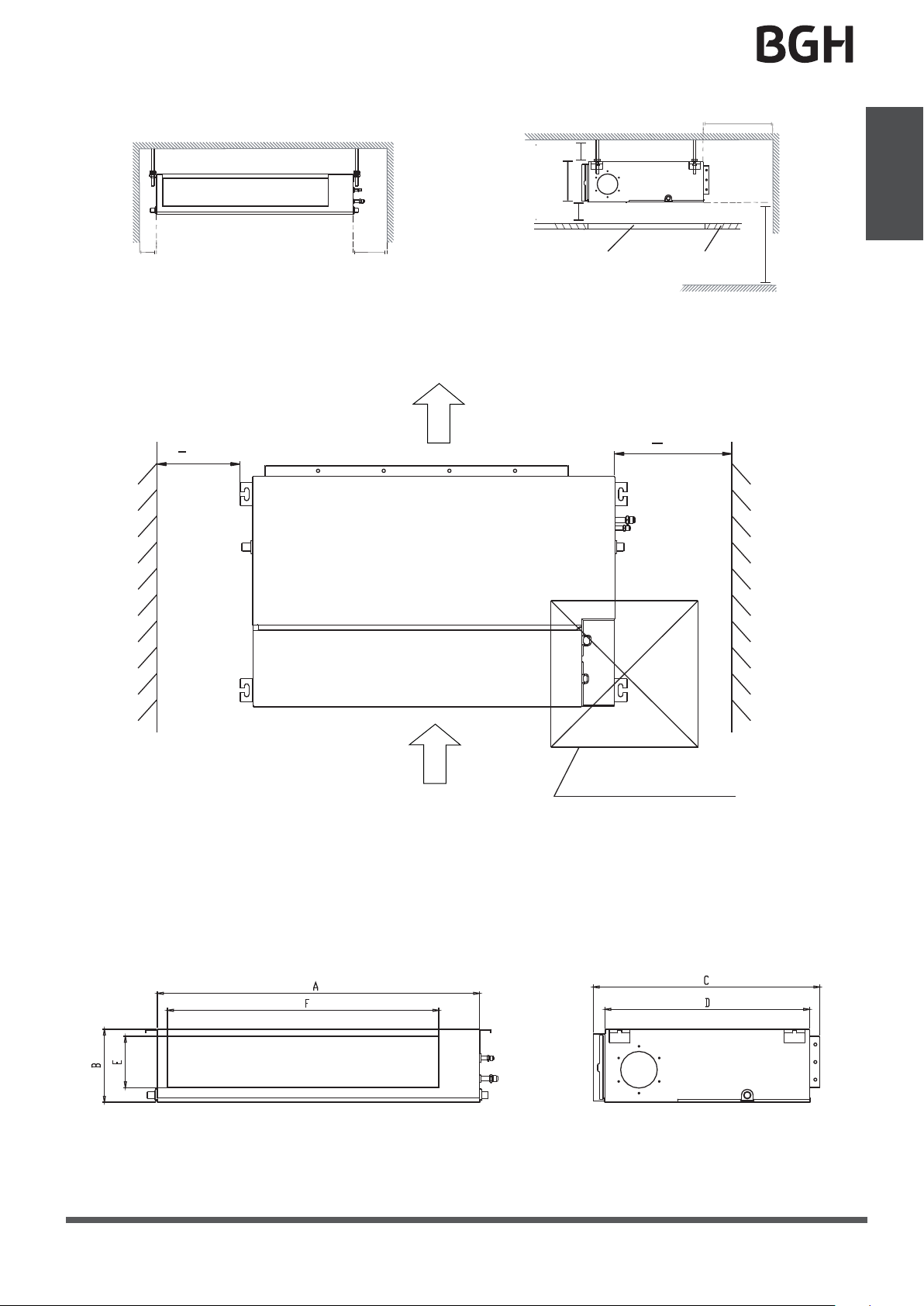
Installation place
Strong and durable ceiling
Left
side
Indoor unit
Right
side
>0.8in(2cm)
B
>0.8in(2cm)
>11.8in(30cm)
Indoor Unit
Installation
>4in(10cm) >11.8in(30cm)
Maintenance space
> (20cm)
7.9
in
Air outlet
Service access Ceiling
Floor
> (30cm)
11.8in
(When no ceiling)
> 8.2in(250cm)
Air inlet
23.6inx23.6in (60cmx60cm)
checking orifice
Fig. 4.2
Step 2: Hang indoor unit.
1. Please refer to the following diagrams to locate the four positioning screw bolt holes on the
ceiling. Be sure to mark the paces where you will drill ceiling hook holes.
Air outlet dimensions
Page 9
Indoor Unit
Installation
Air inlet dimensions
Air filter
Descending ventilation opening and mounted hook
Air filter
Electric control box
Fig. 4.3
Table.4-1 (unit: mm/inch)
MODEL
(Btu/h)
9K/12K
18K 210/8.3 674/26.5880/34.6
24K 249/9.8 774/30.51100/43.3
30K~36K 249/9.8 774/30.51360/53.5
36K~72K 300/11.8 874/34.41200/47.2
A B C
Outline dimension
200/7.9 506/19.9700/27.6
Wood
Place the wood mounting across the roof beam,
air outlet opening size
D E F
152/6 537/21.1450/17.7 186/7.3 741/29.2599/23.6
136/5.4 706/27.8600/23.6
175/6.9 926/36.5700/27.6
175/6.9 1186/46.7700/27.6
227/8.9 1044/41.1800/31.5
New concrete bricks
Inlay or embed the screw bolts. (See Fig. 4.5)
air return opening size
G
190/7.5
228/8.9
228/8.9
280/11
H
Size of mounted lug
I
920/36.2782/30.8
1140/44.91001/39.4
1400/55.11261/49.6
1240/48.81101/43.3
then install the hanging screw bolts.(See Fig.4.4)
Wood mounting
Roof beam
Ceiling
(Blade shape insertion)
Fig. 4.5
(Slide insertion)
Hanging screw bolts
Fig. 4.4
Original concrete bricks
Use an embedding screw bolt, crock, and stick
Steel Roof beam structure
Install and use the supporting steel angle.
(See Fig.4.7)
harness.(See Fig.4.6)
Hanging screw bolt
J
360/14.2
508/20
598/23.5
598/23.5
697/27.4
(Pipe hanging and embedding screw bolt)
Page 10
Steel bar
Embedding screw bolt
Fig. 4.6
Hanging
bolts
Supporting
steel angle
Fig. 4.7
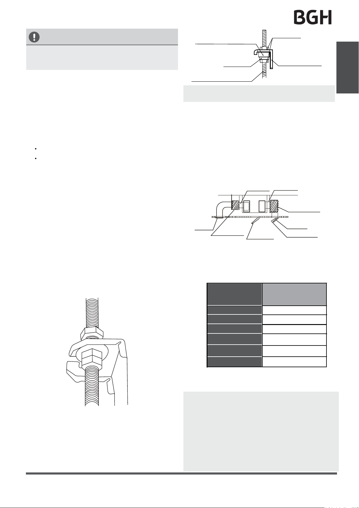
CAUTION
The unit body must be completely aligned with
the hole. Ensure that the unit and the hole are
the same size before moving on.
Shockproof cushion
Washer
Screw nut
Overhang part
Indoor Unit
Installation
2.
Install and fit pipes and wires after you have
finished installing the main body.When
choosing where to start, determine the
direction of the pipes to be drawn out.
Especially in cases where there is a ceiling
involved, align the refrigerant pipes, drain
pipes, and indoor and outdoor lines with their
connection points before mounting the unit.
3.
Install hanging screw bolts.
Cut off the roof beam.
Strengthen the point at which the cut
was made. Consolidate the roof beam.
4. After you select an installation location,align
the refrigerant pipes, drain pipes, as well as
indoor and outdoor wires with their
connection points before mounting the unit.
5.
Drill 4 holes 10cm (4”) deep at the ceiling
hook positions in the internal ceiling. Be sure
to hold the drill at a 90° angle to the ceiling.
6.
Secure the bolt using the washers and nuts
provided.
7.
Install the four suspension bolts.
8.
Mount the indoor unit with at least two
people to lift and secure it. Insert suspension
bolts into the unit’s hanging holes. Fasten
them using the washers and nuts provided.
(See Fig. 4.8).
Hanging screw bolt
NOTE:
Confirm the minimum drain tilt is 1/100
Fig. 4.9
or more.
Step 3: Duct and accessories installation
1. Install the filter (optional) according to the size
of the air inlet.
2. Install the canvas tie-in between the body and
the duct.
3. The air inlet and air outlet duct should be far
enough apart enough to a avoid air passage
short-circuit.
Connect the duct according to the following
4.
diagram:
Air outlet
Isolation booth
Canvas tie-in Canvas tie-in
Isolation booth
Air inlet
checking orifice
Air dust filter
Fig. 4.10
5. Refer to the following static pressure guidelines
when installing the indoor unit.
Table.4-2
MODEL
(Btu/h)
Static Pressure
(Pa/in.wg)
Fig. 4.8
9. Mount the indoor unit onto the hanging
screw bolts with a block. Position the
indoor unit flat using a level indicator to
prevent leaks. (See Fig. 4.9).
9K
12K
18K
24K
30K~36K
60K~72K
0~50/0~0.2
0~50/0~0.2
0~100/0~0.4
0~160/0~0.64
0~160/0~0.64
0~160/0~0.64
Change the fan motor static pressure
according to external duct static pressure.
NOTE: 1. Do not place the connecting duct
weight on the indoor unit.
2. When connecting the duct, use an
nonflammable canvas tie-in to prevent
vibrating.
3. Insulation foam must be wrapped outside the
duct to avoid condensate. An internal duct
underlayer can be added to reduce noise,
if the end-user requires.
Page 11
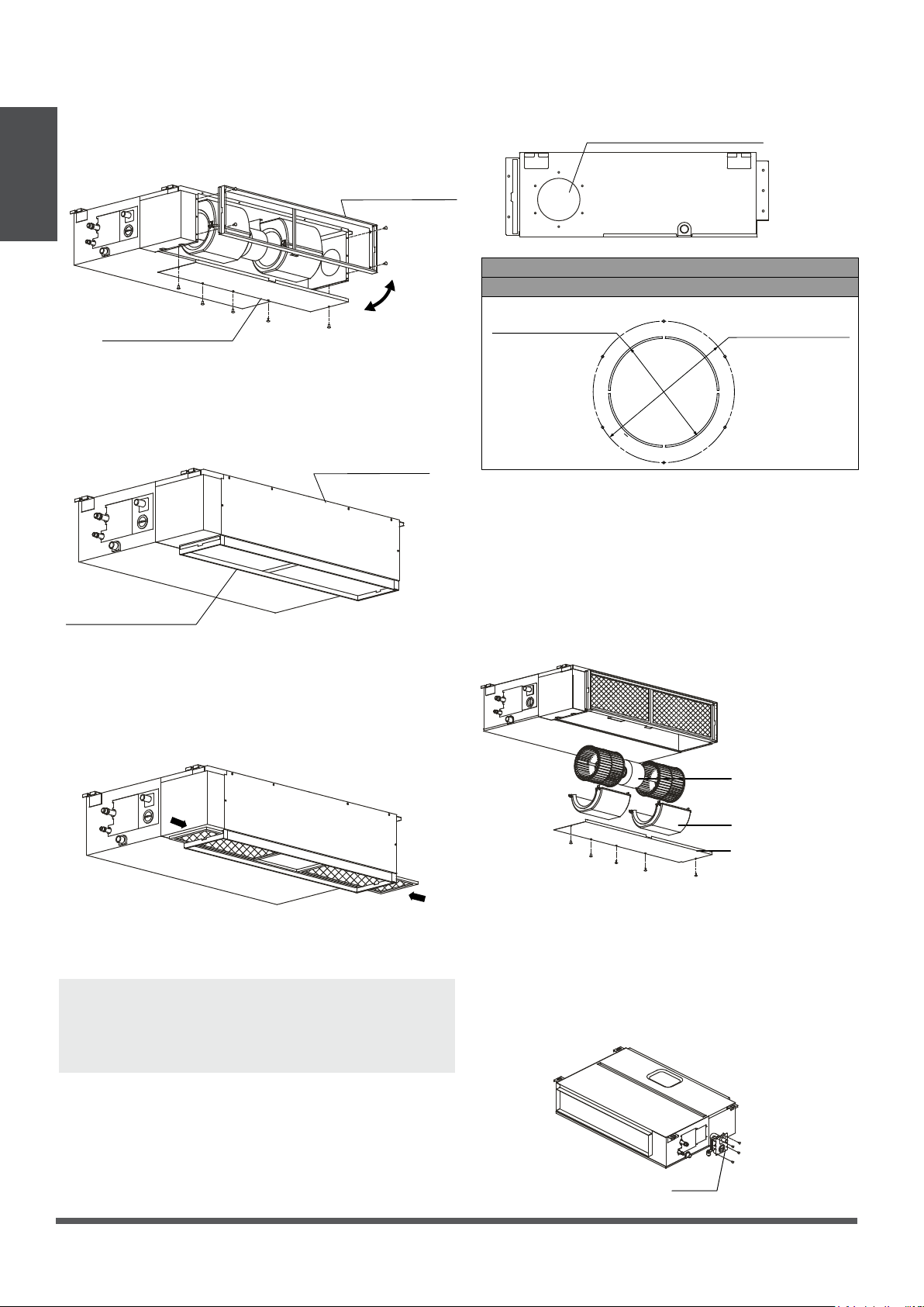
Step 4: Adjust the air inlet direction
(from rear side to under-side).
Indoor Unit
Installation
1. Take off the ventilation panel and flange.
Step 5: Fresh air duct installation
Dimension :
Duct joint for fresh air
Air return flange
MODLE
18-60
Ventilation panel
Fig. 4.11
2. Change the mounting positions of the
ventilation panel and air return flange.
Ventilation panel
Air return flange
Fig. 4.12
3. When installing the filter mesh, fit it into the
flange as illustrated in the following figure.
Ø125mm(4.92”)
Ø160mm(6.3”)
Fig. 4.14
Step 6: Motor and drain pump maintenance
(the rear ventilated panel is used as an example)
Motor maintain:
Take off the ventilated panel.
1.
Take off the blower housing.
2.
Take off the motor.
3.
Fig. 4.13
NOTE: All the figures in this manual are for
demonstration purposes only. The air conditioner
you have purchased may be slightly different in
design, though similar in shape.
Motor
Blower housing
Ventilated panel
Fig. 4.15
Pump maintainance:
Remove four screws from the drain pump.
1.
Unplug the pump power supply and water
2.
level switch cable.
Detach the pump.
3.
Pump
Fig. 4.16
Page 12
Outdoor Unit Installation
Strong wind
Outdoor Unit Installation Instructions
Step 1: Select installation location.
The outdoor unit should be installed in the
location that meets the following requirements:
√
Place the outdoor unit as close to the indoor
unit as possible.
√
Ensure that there is enough room for
installation and maintenance.
√
The air inlet and outlet must not be
obstructed or exposed to strong wind.
√
Ensure the location of the unit will not be
subject to snowdrifts, accumulation of leaves
or other seasonal debris. If possible, provide
an awning for the unit. Ensure the awning
does not obstruct airflow.
√
The installation area must be dry and well
ventilated.
√
There must be enough room to install the
connecting pipes and cables and to access
them for maintenance.
5
√
The area must be free of combustible gases
and chemicals.
√
The pipe length between the outdoor and
indoor unit may not exceed the maximum
allowable pipe length.
√
If possible, DO NOT install the unit where it
is exposed to direct sunlight.
√
If possible, make sure the unit is located far
away from your neighbors’ property so that
the noise from the unit will not disturb them.
√
If the location is exposed to strong winds (for
example: near a seaside), the unit must be
placed against the wall to shelter it from the
wind. If necessary, use an awning.
(See Fig. 5.1 & 5.2)
√
Install the indoor and outdoor units, cables
and wires at least 1 meter from televisions or
radios to prevent static or image distortion.
Depending on the radio waves, a 1 meter
distance may not be enough to eliminate all
interference.
Outdoor Unit
Installation
Strong wind
Fig. 5.1 Fig. 5.2
Step 2: Install outdoor unit.
Fix the outdoor unit with anchor bolts (M10)
>60cm / 23.6”
CAUTION
• Be sure to remove any obstacles that
Fix with bolts
may block air circulation.
• Make sure you refer to Length
Specifications to ensure there is
enough room for installation and
maintenance.
Strong wind
Fig. 5.3
Page 13
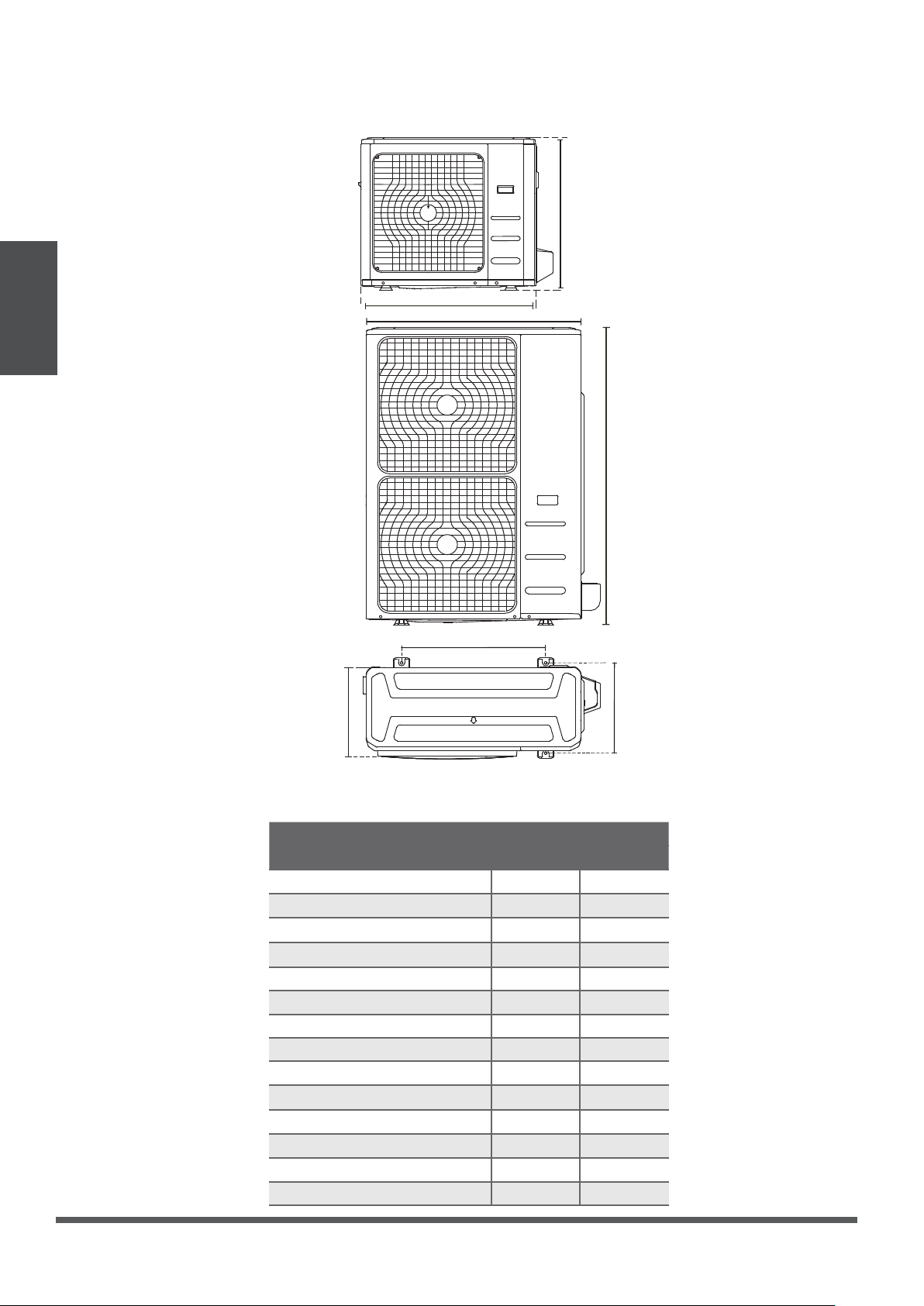
Outdoor Unit
Installation
Split Type Outdoor Unit
(Refer to Fig 5.4, 5.5, 5.6, 5.10 and Table 5.1)
H
Fig. 5.4
W
W
H
Fig. 5.5
A
D
B
Fig. 5.6
Table 5.1: Length Specifications of Split
Type Outdoor Unit (unit: mm/inch)
Outdoor Unit Dimensions
W x H x D
770x555x300 (30.3x21.85x11.81) 487 (19.2) 298 (11.73)
810x558x310 (31.9x22x12.2) 549 (21.6) 325 (12.8)
845x700x320 (33.27x27.5x12.6) 560 (22) 335 (13.2)
900x860x315 (35.4x33.85x12.4) 590 (23.2) 333 (13.1)
945x810x395 (37.2x31.9x15.55) 640 (25.2) 405 (15.95)
990x965x345 (38.98x38x13.58) 624 (24.58) 366 (14.4)
938x1369x392 (36.93x53.9x15.43) 634 (24.96) 404 (15.9)
900x1170x350 (35.4x46x13.8) 590 (23.2) 378 (14.88)
800x554x333 (31.5x21.8x13.1) 514 (20.24) 340 (13.39)
845x702x363 (33.27x27.6x14.3)
946x810x420 (37.24x31.9x16.53) 673 (26.5)
946x810x410 (37.24x31.9x16.14) 673 (26.5)
952x1333x410 (37.5x52.5x16.14) 634 (24.96)
952x1333x415 (37.5x52.5x16.34) 634 (24.96)
Mounting Dimensions
Distance A Distance B
540 (21.26)
350 (13.8)
403 (15.87)
403 (15.87)
404 (15.9)
404 (15.9)
Page 14
 Loading...