

Page 1
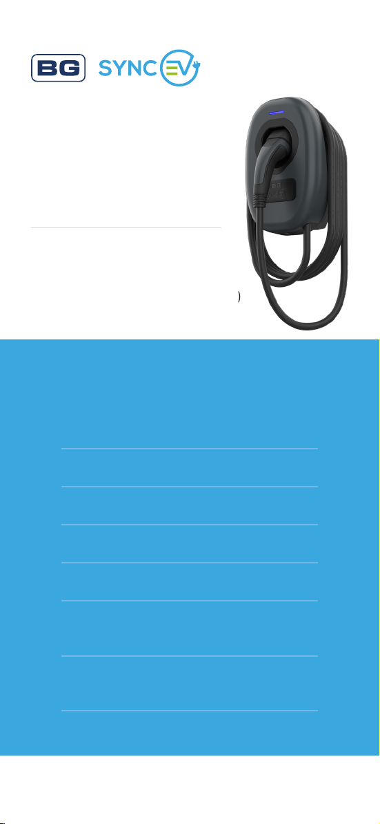
Wall Charger 2
Installation
Guide
7.4kW TETHERED SINGLE PHASE :
EVWC2T7G (7.4KW / WI-FI / LAN)
EVWC2T7GG (7.4KW / WI-FI / LAN / 4G)
Contents
click to navigate directly to the page
Introduction / Box contents
Safety information
Installation & testing
Troubleshooting
Commercial Installation & Commissioning
Domestic Commissioning
Stage 1 (Installer app)
Domestic Commissioning
Stage 2 (User app setup)
Technical
syncev.co.uk
EVWC2T7G EVWC2T7GG V2 0823 GJW
Page 2
Introduction
This guide is intended for use by
competent electrical installers to
explain basic requirements and
options to be considered when
installing a BG SyncEV charger.
The unit is designed for installations
inside or outside, the advanced
safety technology we have built
into the unit ensures its safe usage.
This guide provides information to
assist when installing the EVWC2Sx
chargers and should not be used
3
WARRANTY
with other EV chargers.
Box contents
• EV charger with 7.5m tethered cable and
Type 2 charging gun
• Decorative fascia
• Installation template & quick start guide
• Accessories pack containing:
year
» Power connector
» Cord grip and screws
» M25 gland
» 25mm blind grommet
» Bonded sealing washers
» Assembly screws
» Anti-tamper bit
» x1 CT clamp
(EVA120CT1)
» x1 CT clamp connector
Tools required
Hex bit holder, PZ2 screwdriver, suitable drill bit
and fixings
Return to Contents
Page 3

Safety information
Warning: The supplied BG SyncEV charger
is manufactured to be safe without risk
provide they are installed correctly, used, and
maintained in accordance with the manufacturers
recommendations and installed by a competent
electrical installer in accordance with national
and local regulations and legislation applicable
at the time of installation, e.g. BS7671:2018
amendment 2.
The EV Charger is suitable for use with a single
phase (for up-to 7.4kW charging) 220-240V
Nominal AC supply.
The supply should run from a dedicated 40A
circuit breaker. We recommend the use of a Type
B curve circuit breakers. The EV charger features
an integral 30mA type-A RCD with 6mA DC
leakage detection and therefore an external RCD
is not usually required:
1. For cables without earthed metallic covering
installed in walls or partitions at a depth of
less than 50mm and also within walls and
partitions with metal parts, and not protected
by steel conduit or similar then RCD
protection is required.
2. If the cable is clipped directly to the surface
of a wall and does not pass through a wall or
partition to the EV charger then a standard
B type 40A MCB may be installed into the
Consumer unit, however RCD protection
may be required for other reasons such as
if it forms part of a TT system and the earth
Return to Contents
Page 4

fault loop impedance values cannot be met.
This will be in compliance with the current
BS7671 Amendment 2 Wiring Regulations.
To conform with BS 7671, on occasions a two
pole MCB/RCD or other means of isolation
may be required.
Important note: A DC Leakage fault in the
vehicle may “blind” a type “AC” RCD and render
it ineffective, never feed any EVSE From an
upstream Type “AC” RCD.
Earthing requirements
The supplied EV charger features an on-board
safety monitoring system to detect low or high
voltage supplies and potential earth-neutral faults,
this in accordance with regulation 722.411.4.1
(iv) of BS7671 2018. If such a condition is
encountered the charge cycle is ended or
prevented and the EV charger indicator flashes
red and effectively becomes a double insulated
(class II) device. The vehicle becomes isolated
in accordance with Regulation 543.3.3.101(ii)
from incoming supply and poses no risk to
touch. This feature removes the requirement for
an earth electrode where it may be ineffective or
introduce further risk.
The EV charger may be connected directly
to a TN-C-S (PME) earthing system without
any special arrangements. It remains the
responsibility of the installer to conduct a risk
assessment of the immediate area to a range
of 10 meters (equipotential zone) to ensure no
other conductive metal fixings pose risks (mixture
Return to Contents
Page 5

of TT/TN-S and TN-C-S), this is important where
cable length may enable charging inside or
outside of a building/garage where the vehicle is
within touch distance.
Where certain conditions dictate an earth
electrode must be used it shall be independent
from the distributors earth system with no direct
interconnection (the incoming supply SWA
protective earth should be isolated from the
housing and/ or earth electrode). The electrical
installer shall install a suitable electrode complete
with termination housing and covers where
appropriate, warning labels should be visible
and close to the unconnected SWA protective
earth, e.g. inside the charger.
The earth connection shall be made from the
electrode to the charger via copper conductor
earth wire of an appropriate CSA for the
installation. The earth wire shall be installed
in conduit where there is a risk of mechanical
damage or UV exposure. Recommended Earth
electrode impedance to be <100 ohms.
Return to Contents
Page 6

Surge protection
Guidance on requirements for surge protection
devices given In BS7671: section 443.
The EV charger is protected against transient
over voltages (+/-2kV Line-Earth and +/-1kV LineLine as a requirement of EN 61000-6-1), a direct
lightning strike carries a current of 30~ 200kA
the EV charger’s internal protection would
provide little or no protection in such an event,
likewise nor would an SPD rated less than 30kA.
If life support equipment or business operations
could be affected by a lightning strike central
SPD protection is advised if it does not already
exist.
The guidance on risk calculation in section 443.5
of BS7671 in most cases is not possible due
to unknown location of any SPD already fitted,
length of cables to calculate LP etc, it is therefore
recommended a common sense approach is
used on choice of SPD (or if required).
Return to Contents
Page 7

Isolation and switching for safety
and maintenance
To ensure the EV charger can be “turned off”
to enhance security and enable maintenance
activities, a two pole isolator (or DP RCD or
RCBO) suitably rated must be installed within the
customer’s property.
An isolator switch is a mandatory requirement for
“new builds”, but optional for existing dwellings
(at customer’s request), the switch should be
mounted between 500mm and 1500mm above
finished floor level to comply with regulations.
The switch should be rated at 45 Amps.
All installations must comply to BS7671: 2018.
Return to Contents
Page 8

Installation requirements
The EV charger is suitable for installation inside
and outside on a solid wall or structure.
The installer should consult with the building
owner to establish their preferred installation
location. This should take into consideration
the length of charging cable and risk of vehicle
impact etc.
It is recommended the charger is installed at
a height of 500mm-1500mm as per building
regulations BS8300:2018.
If no suitable permanent structure is available,
the EV charger can be mounted to a stand.
We recommend of the BG SyncEV stand,
EVASTAND12S (single) or EVASTAND12T (twin).
Ensure suitable fixings are used depending on
the mounting surface. To avoid unnecessary
dust inside the enclosure, it is recommended to
use the included fixing hole template drill the
surface, before fitting the enclosure.
Ensure installation wall has been checked for
electric cabling or pipework with a suitable
detector.
NOTE: if any groundworks are required e.g.
cable trenching or earth electrode fitment, it is
advisable to check if underground services could
be present before commencement. Plans may be
available at: www.linesearchbeforeudig.co.uk
(free to domestic users).
Return to Contents
Page 9

The EV charger is suitable for bottom or rear
cable entry, if using rear cable entry ensure
the included 25mm rubber grommet is used to
maintain the IP rating.
If using SWA cable the included 25mm
compression gland is NOT suitable, an
alternative gland will be required.
When using SWA please supply the charger
from the bottom left cable entry point.
A maximum hole size of 32mm is acceptable
at this location. Its advisable to earth the SWA
armouring at the supply end of the cable.
Do not drill alternative cable entries into the
charger housing, except marked cable entry
location for rear or bottom entry.
We recommend using BG SyncEV Power &
Data Combined cable on installs that require
a CT clamp to use the chargers dynamic load
management capabilities.
All of the cables that are to be connected in to
the supply connector should have their insulation
striped back 18-20mm. Connectors supplied are
suitable for cables of 4-10mm².
Return to Contents
Page 10
Load balancing
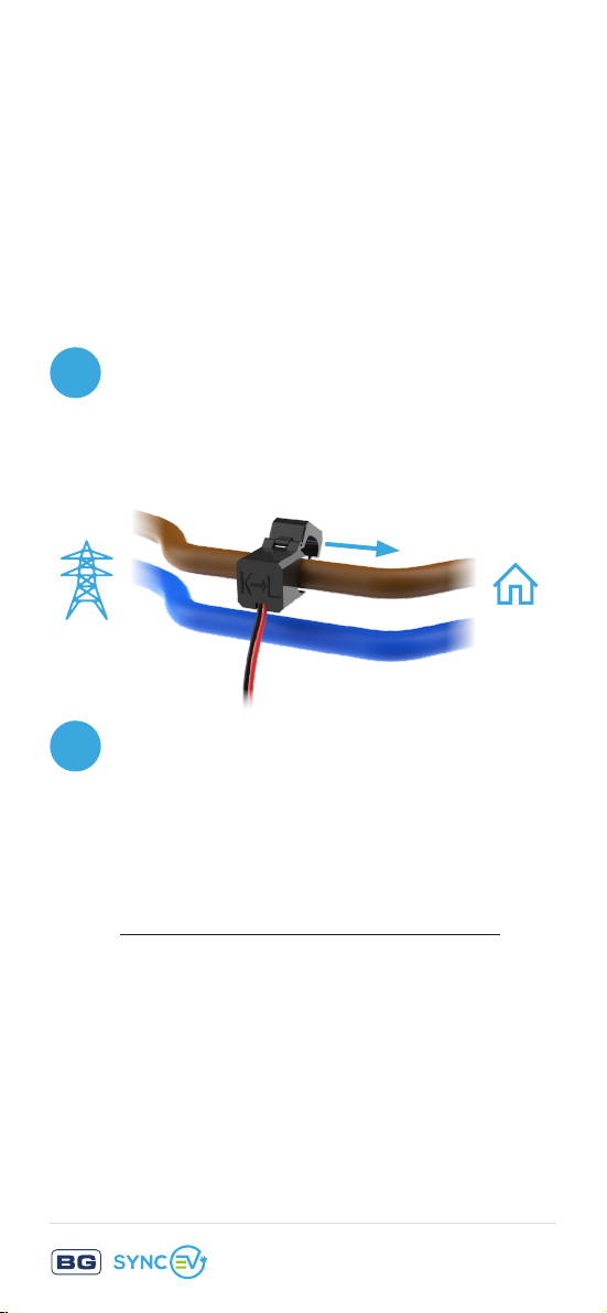
If load balancing is required, a CT clamp should
be used for correct balancing. One BG SyncEV
CT clamps, EVA120CT1, is supplied in the box
with this charger. This should be fitted around
the incoming power to the main fuse and the
correct max load (A) to be entered during setup
and installation steps.
Locate the main incoming power cable
1
into the property. The CT Clamp needs to
be fitted before any of the tails are split
for correct measurement.
Open the CT Clamp and fit around the
2
incoming Live power cable, this is typically
marked brown for most installations.
Ensure the Arrow is pointing into the
property from the incoming fuse.
K towards Source, L towards Load.
External Mid Metering - RS485
If using an external Mid Meter connected via a
RS485 connection the Dip switches need to be
set. Dip 2 Up/On is required for external Mid
Meter use.
Return to Contents
Page 11

Final Electrical testing
To meet the BS7671:2018 (18th edition)
requirements for testing of an electrical
installation, the following tests and checks shall
be performed by a competent electrical installer
before during and after a BG SyncEV charger is
installed:
• A visual inspection of the installation
including the existing electrical installation.
• Verification of the characteristics of the
electrical supply at the origin of the
installation to confirm the supply is suitable
for the additional load.
• A test to confirm the continuity of the circuit
protective conductors.
• A test to confirm the integrity of the circuit
insulation resistance.
• A test to confirm the polarity of the
installation is correct.
• Where applicable a test to confirm the earth
electrode resistance is within acceptable
tolerances.
(or)
• An earth loop impedance test.
Return to Contents
Page 12

• A test of the mechanical operation of
residual current devices (RCD’s).
• A test to confirm the operation of residual
current devices (RCD’s) is within stipulated
time scales (at the rated current and at five
times the rated current operating current).
• A test or calculated measurement of the
prospective fault current.
• A verification of the functional operation of
the EV charger.
• An electrical installation certificate must be
completed.
Ensure electrical testing is done before EV
charger commissioning and network setup is
performed.
For this testing, the Charger can be set to “Plug
and Charge” Mode in the installation App.
Return to Contents
Page 13
Electrical Installation
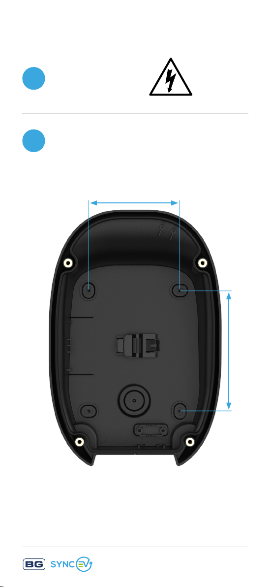
Isolate the power
1
Use the included hole template to
2
drill fixing holes
110 mm
145 mm
Return to Contents
Page 14
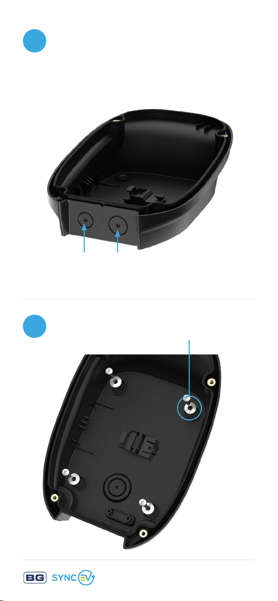
Drill base for required cable entry.
3
Suitable for 16-32mm hole size.
If using rear entry, ensure
included 25mm grommet is used
Left for
SWA cable
Ensure the supplied washers are
4
used to maintain IP rating
Right for rubber/
flex cable
Return to Contents
Page 15
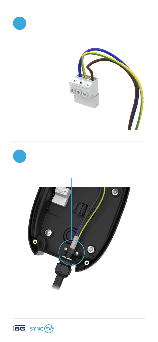
Ensure correct polarity when
5
making incoming power
connections
3 pin plug:
N - Blue
E - Yellow/Green
L - Brown
Ensure supplied cord grip is fitted
6
on incoming power cable if using
bottom cable entry location
Return to Contents
Page 16
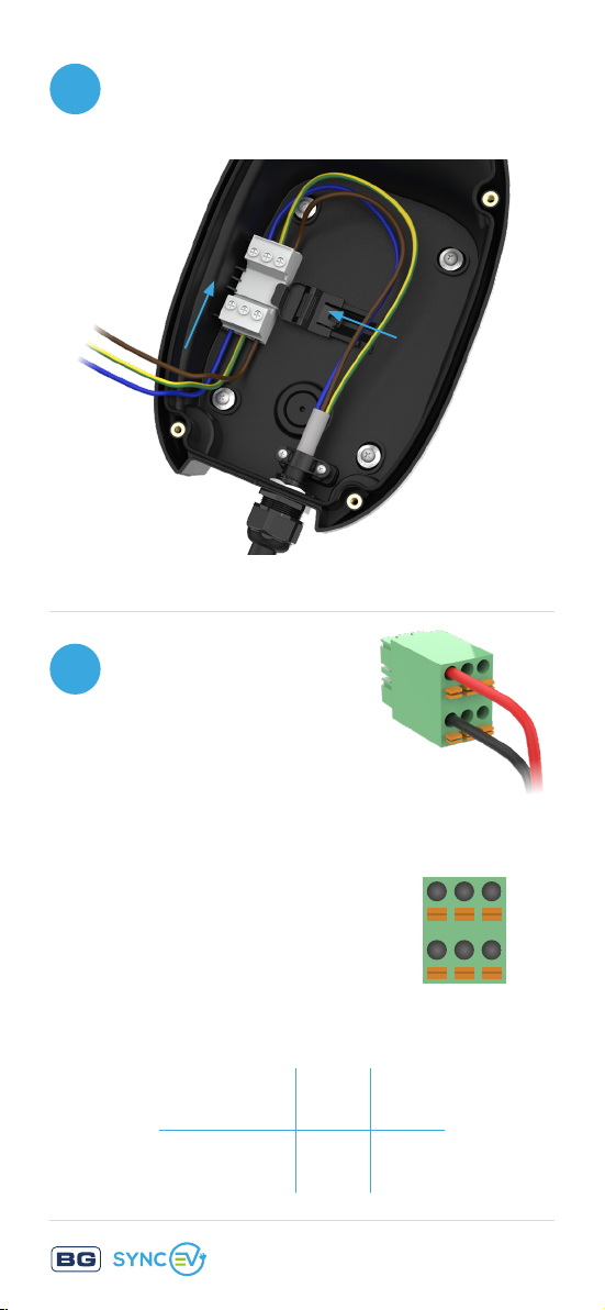
Ensure Power connector is fully
7
inserted then slide clip to secure
For dynamic load
8
balancing, insert
wires into the small
connector
If using external
485 meter, then dip
switch 2 needs to
be changed to ‘On’
1 32
+
1 2 3
485A PV CT
+
485B PV CT
‒
‒
Return to Contents
Page 17
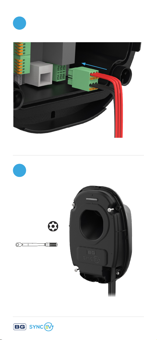
Plug connector into PCB, ensure
9
correct polarity
10
Fix charger to the base ensuring
correct torque settings
T25S Security Torx
2.5 Nm
Return to Contents
Page 18
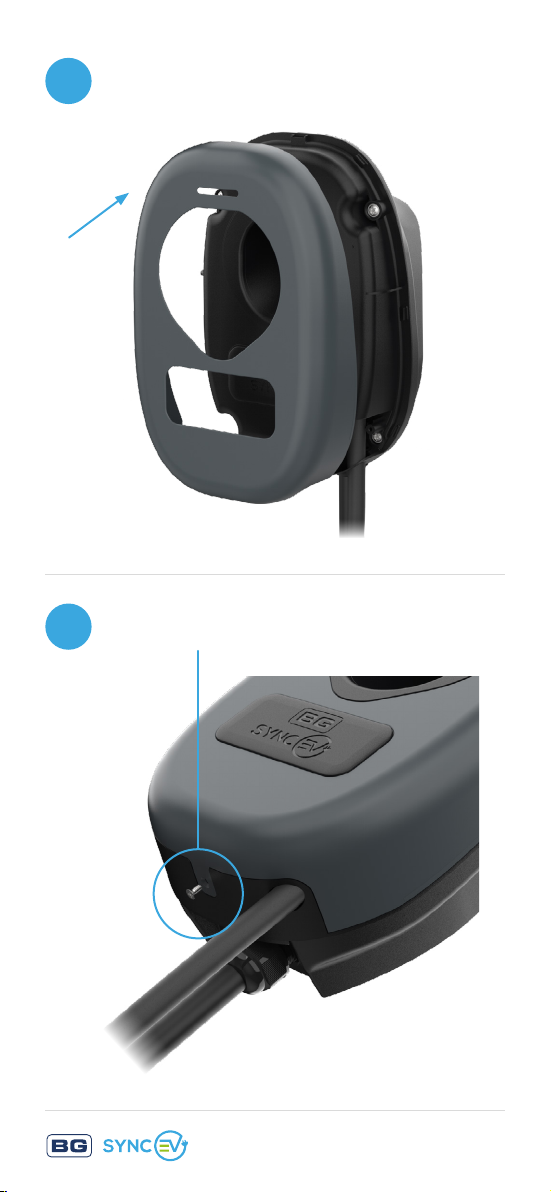
11
Snap front cover trim into place
12
Fit locking screw to secure cover
Return to Contents
Page 19

Troubleshooting
For further information, or to refer to our
FAQs, please visit our website:
www.syncev.co.uk
The status of the EV charger can be identified
by referencing the colour shown on the LED
indicator:
• Solid Blue – Standby – Charger has power
and is connected to the network. Or, if in
‘plug and charge’ mode is not connected to
the network, is ready to charge.
• Flashing BLUE – Charger is connected but
not charging, awaiting confirmation of charge
in APP or scheduled start time
• Solid Dark Green – Charger is active and
Charging
• Solid Yellow – Charger is offline from
network, check local network is active and
Wi-Fi is working on the 2.4Ghz band
• Flashing Red – Indicates the charger is in
fault mode and has stopped charging for users
safety
Potential causes:
• Internal RCD has tripped
• Vehicle fault
• Under or over suitable charging voltage
Remove connection to the vehicle and
reset power to the EV charger.
Return to Contents
Page 20

Commercial / Workplace / Fleet
installation & commissioning
4 simple steps:
1
CONTACT
Email [email protected] with the
charge-point owner contact details
2
CONNECT
Install the charge-points
3
CONFIGURE
Set the configurations in the
BG SyncEV installer app and connect
all chargers to the internet
4
COMPLETE
Pass the charger details to the
charge-point owner
How it works:
To streamline the process, email us
before the first day of installation
with the following information:
Return to Contents
Page 21

• Model and charger ID
(for every charger in the installation)
• Contact details for the charge-point owner:
• Company name
• Name of charge-point manager
• Site address
• Telephone number for
charge-point manager
• Email address for charge-point
manager
Our Commercial Team will contact the
charge-point owner to carry out the quick and
simply Monta setup process.
By using this process we will have the
back-office set up for installation day,
ensuring all chargers are immediately ready
for customer use once configured.
Return to Contents
Page 22
Domestic Commissioning
Stage 1 of 2
INSTALLER APP - Download the ‘BG SyncEV
Installer’ app by clicking this link
Also available from the
Installer Portal on the
syncev.co.uk website, or using
the QR code opposite.
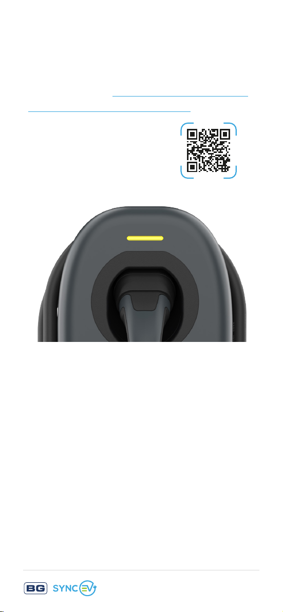
Upon powering the charger, the status indicator
light will show Yellow. This indicates that the
charger is ready for network setup but is not yet
connected to the internet.
For Wi-Fi connection we recommend that the
router is set to only 2.4GHz band to reduce
the risk of possible conflicts. Once setup the
router can be restored to both 2.4GHz & 5GHz
bands.
Return to Contents
Page 23
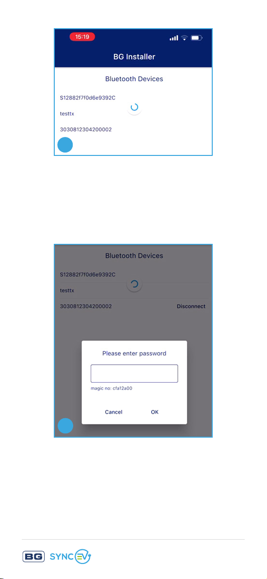
1
1. Ensure Bluetooth is active on your device.
Open the BG EV Charging App and select
the Charger ID Code as shown on the
charger identification label.
2
2. Then enter the password shown on the
identification label.
Return to Contents
Page 24
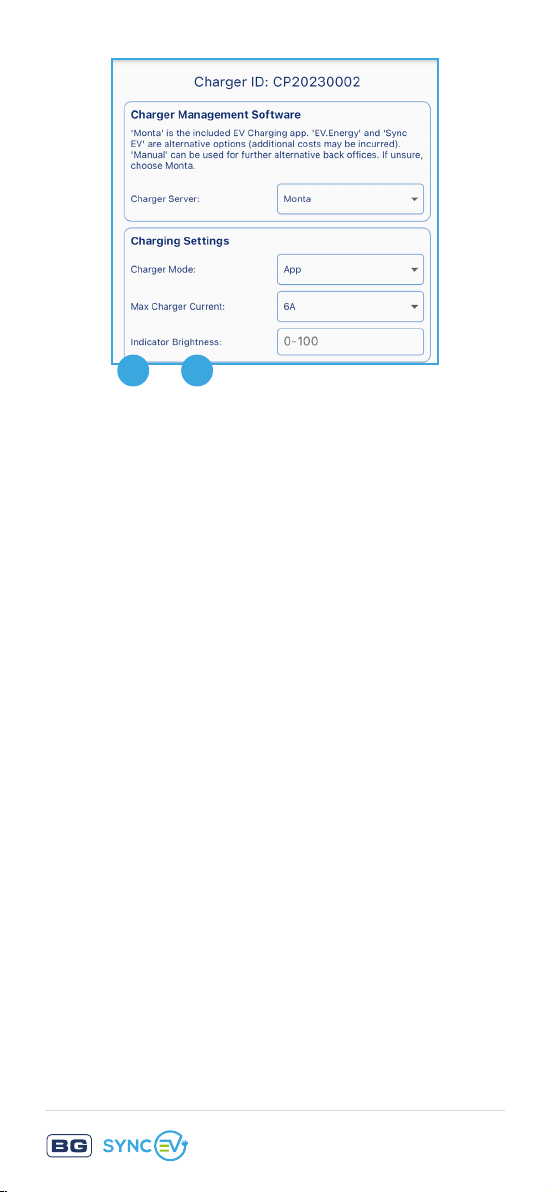
–
3 6
3. Select ‘Monta’ - this is the included app.
‘EV.Energy’ and ‘SyncEV’ are alternative
options (additional costs may be incurred).
‘Manual’ can be used for other alternative
back offices. If unsure, choose ‘Monta’.
4. Charge Mode:
‘APP’ for smart charging via the consumer
App (see next page);
‘Plug and Charge’ for non-smart charging.
Use ‘Plug and Charge’ if connection to
server cannot be established and car
charging is required.
5. Max Charger Current:
Set to max current supported by installation
if less than default 32A.
6. Indicator Brightness:
Adjust from 1 to 100% to change the
brightness of the status indicator.
Return to Contents
Page 25
–
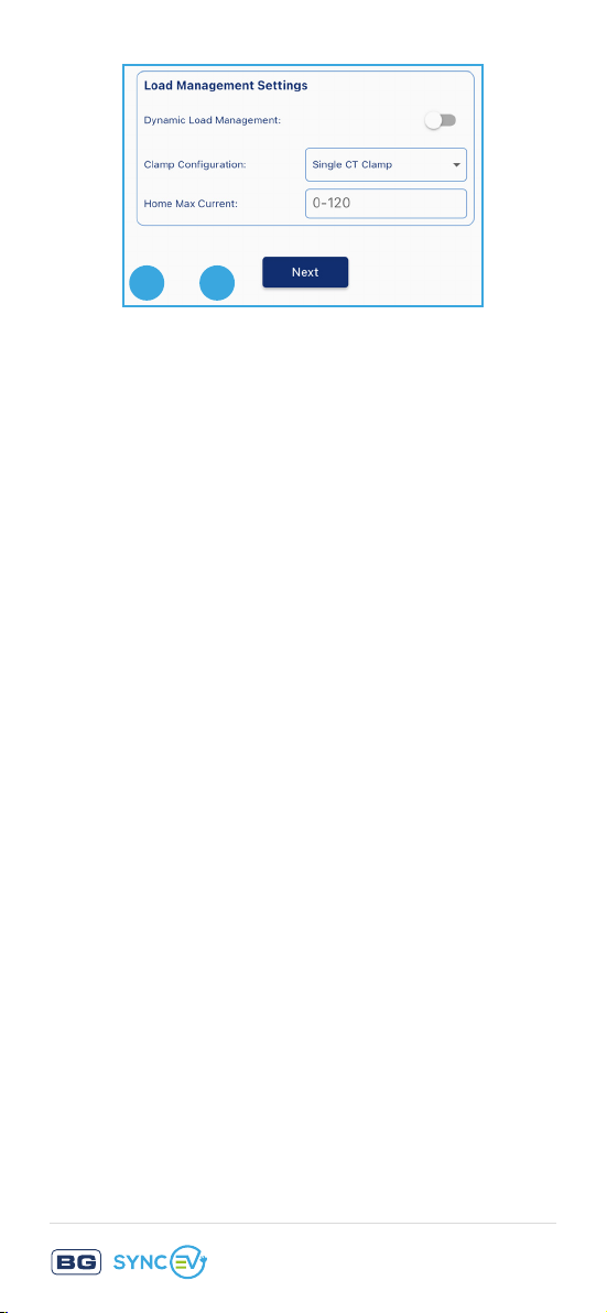
7 8
7. Dynamic Load management:
If dynamic load management is required
then toggle right and select Clamp
Configuration.
8. Home Max Current:
For load balancing this should be the same
or less than the main fuse rating. EV charger
will reduce its charging rate to limit the
total home load to be under the limit. If the
available current is under the minimum of
6A the EV charger will pause the charging
session.
Press Next to save these settings.
Return to Contents
Page 26
9
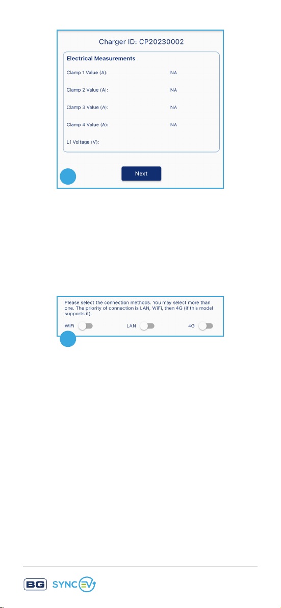
9. Check the shown electrical measurements
match measured readings. This will allow
checking the Load management CTs are
fitted correct orientation.
Press Next to continue
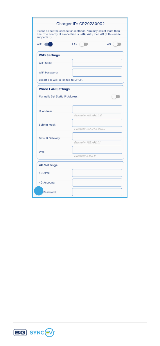
10
10. Choose between Wi-Fi, 4G and LAN.
• For Wi-Fi select the SSID network name
and enter password.
• For LAN ensure that “Manually set Static
IP Address” is set to OFF
(unless advanced settings are required).
• For 4G the setting will have been
pre-configured.
Multiple options can be selected if
required, this will allow a fall-back, e.g
From Wi-Fi to 4G if fitted in case of
network loss.
Return to Contents
Page 27
11
11. On LAN the charger will default to DHCP.
If static IP is required for the network
connection, set the option “Manually Set
Static IP Address” to OFF and a manual IP
address can be entered.
12. Press next to start network connection, the
charger will attempt a network connection,
If successful will then reboot to complete an
RCD and function check.
Return to Contents
Page 28
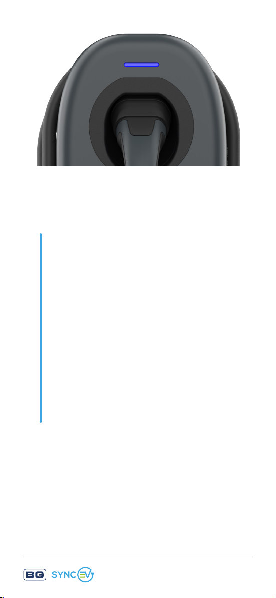
In less than 2 minutes, the indicator should
turn from Yellow to Blue to confirm network
connection.
If the charger continues to show yellow,
power cycle (switch off/on at fuse board)
and reconnect via the app to check the
settings are correct.
If still unable to connect to the network
but need to use the charger then change
the Charge Mode to ‘Plug and Charge’
and press ‘SET’ again to re-update
settings.
If unable to establish network connection
call 01952 983 940
or email: [email protected]
Note: The network connection from the device
to the Internet is fully encrypted and secure.
Additionally, no user data is stored on the
charger.
Return to Contents
Page 29
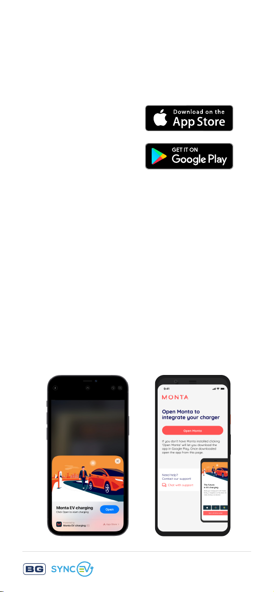
STEP 3
OPEN THE APP
Follow the links to open the app.
Android
STEP 4
CREATE YOUR ACCOUNT
Create your account using your phone number or
social logins (Apple/Google/Microsoft).
Domestic Commissioning
Stage 2 of 2
1. Download the Monta smart app:
Apple app store
click here
Google play store
click here
or search for ‘Monta EV charging’ on
Apple app store or Google Play
2. Using your smart-phone scan the unique
sheet supplied with the EV Charger.
If you’re unable to use the QR, open a web
browser on your smart-phone and manually
Monta QR Code on the ‘Quick Start Guide’
type the URL on the sticker
3. Open the Monta app
iOS
Android
Return to Contents
Page 30
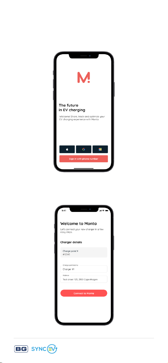
4. Create an account using your customers
SUCCESSFUL CONNECTION
When you reach this step, your charge point is con-
nected and you can use Monta to start charging.
phone number or social logins (Apple/
Google/Microsoft)
5. Connect the EV charger to Monta - name the
charge-point and set the location
Return to Contents
Page 31
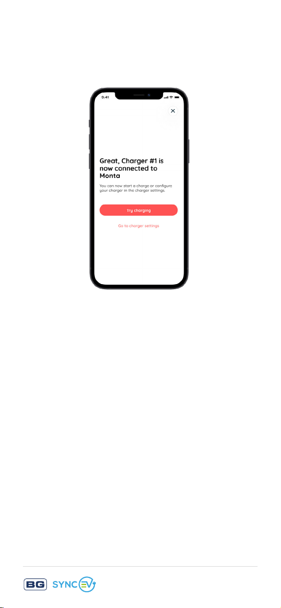
6. Successful connection - When you reach this
step, your charge-point is connected and you
can use Monta to start charging
Need help with the app?
Contact Monta customer support through the app
or via the website Monta.com
Need help with the charge-point?
Contact BG SyncEV technical support at:
or via the website at www.syncev.co.uk
Return to Contents
Page 32

Technical information
Environmental Protection
This symbol is known as the “Crossedout Wheelie Bin Symbol”. When this
symbol is marked on a product or
battery, it means that it should not
be disposed of with your general
household waste. Some chemicals
contained within electrical/electronic
products or batteries can be harmful
to health and the environment. Only
dispose of electrical/electronic/battery
items in separate collection schemes,
which cater for the recovery and
recycling of materials contained within.
Your co-operation is vital to ensure the
success of these schemes and for the
protection of the environment.
Guarantee
BG SyncEV products are guaranteed against
faulty materials and workmanship for a period
of 3 years from date of delivery: products will
be repaired or (at BG SyncEV’s discretion)
replacements will be supplied or (at BG SyncEV’s
discretion) a credit note will be issued.
This guarantee is subject to BG SyncEV’s
conditions of sale and in particular to the
following conditions being met:
Return to Contents
Page 33

1. Notification of any defect is given to BG
SyncEV as soon as reasonably practicable
after becoming apparent, and the products
then returned to BG SyncEV.
2. The products have only been operated under
normal operating conditions and have only
been subject to normal use.
3. No work (other than normal and proper
maintenance) has been carried out to the
products without BG SyncEV’s prior written
consent.
4. The products have been assembled, or
incorporated into other goods, by a qualified
and recognised electrician and only in
accordance with any instructions issued by
BG SyncEV.
5. The defect has not arisen from an item
manufactured or supplied by a person other
than BG SyncEV.
6. 3 year warranty as standard, optional product
registration can be completed on the
BG SyncEV website.
Follow this link to visit our Warranty web-page
Return to Contents
Page 34

Technical data
CODES : EVWC2T7G
TYPE : TETHERED
SOCKET / PLUG : TYPE 2 PLUG
KW : SINGLE PHASE : 7.4KW, 32A MODE 3
MIN CHARGE
CURRENT :
ELECTRICAL INPUT : SINGLE PHASE : 220-240V, 50-60Hz
COLOUR : BASE & BODY RAL 9005 (BLACK)
CABLE
MANAGEMENT :
PEN PROTECTION : YES, IN-BUILT EARTH DISCONNECTION
EARTH ROD : NOT REQUIRED
RCD PROTECTION : YES, 6mA DC, 30mA AC TYPE-A, IN-BUILT
(7.4KW / WI-FI / LAN)
EVWC2T7GG
(7.4KW / WI-FI / LAN / 4G)
CONFIGURABLE, 6 - 32A
TRIM - RAL 7016 (ANTHRACITE GREY)
OPTIONAL COLOURED TRIMS AVAILABLE
AS ACCESSORIES
BUILT IN CABLE WRAP & HOLSTER
OVERLOAD AND
FAULT PROTECTION :
ELECTRICAL CLASS : CLASS 1, HOUSING CLASS 2
CONSUMER UNIT
REQUIREMENTS :
LOAD BALANCING : 1x EVA120CT1 LOAD MANAGEMENT KIT
METER ACCURACY : 2% CLASS C EQUIVALENT INTERNAL
TERMINALS : COMBI SCREW FIRST FIX PLUG
INDICATOR : RGB LED AND BUZZER
OVER CURRENT AND FAULT PROTECTION
40A MCB OR 30mA TYPE-A RCD
(DEPENDENT ON CABLE TYPE &/OR ROUTE)
INCLUDED
METER WITH OPTION FOR CONNECTION
TO EXTERNAL RS485 MODBUS METER
CONNECTOR
Return to Contents
Page 35

INDICATOR MODES : BLUE - STANDBY, FLASHING BLUE -
PREPARING, GREEN - CHARGING,
YELLOW - NO NETWORK, RED - ERROR
HOUSING : UV STABILISED POLYCARBONATE
WALL FIXING : 4 POINT WITH HORIZONTAL AND
VERTICAL ADJUSTMENT, SUPPLIED FIXING
HOLE TEMPLATE.
FIXING HOLE CENTRES :
110 HORIZONTAL, 145 VERTICAL (MM)
IP / IK RATING : IP55 / IK10
SOC MODULE : AI ESP32-S SOC
WI-FI & ETHERNET : 2.4Ghz 802.11 B/G/N & RJ45
WI-FI SECURITY : WPA/WPA2/WPA2-ENTERPRISE/WPS
BLUETOOTH : 4.2 BR/EDR and BLE
CONNECTION
PROTOCOL :
OCPP 1.6J
4G DATA : MODEL SPECIFIC
3 YEARS INCLUDED, WHEN USED WITH
MONTA (ON THE INCLUDED PACKAGE).
TOP-UP ONLINE TO CONTINUE SERVICE
AFTER 3 YEARS
APP : POWERED BY MONTA
OPERATING TEMP : -25 TO +40°C
†
SOFTWARE &
OVER-THE-AIR
FIRMWARE UPDATE :
WARRANTY : 3 YEARS
STANDARDS &
APPROVALS :
IEC61851-1, IEC61439-7, IEC62955,
IC 61851-21-2, BS EN62196,
EN301 511, EN 301 908-1/2/13,
EN 301 489-3, EN 300 330,
EMC COMPLIANT, CE, UKCA,
THE ELECTRIC VEHICLES (SMART
CHARGE POINTS) REGULATIONS 2021
INCLUDING SCHEDULE 1
Return to Contents
Page 36
SUPPLIED
ACCESSORIES :
1x EVA120CT1 LOAD MANAGEMENT KIT,
5x BASE FIXING WASHERS,
5x ASSEMBLY LID BOLTS, 1x BLANKING
PLUG AND 1x 25MM COMPRESSION
GLAND, USER-SIDE CONNECTOR, CORD
GRIP AND 2x CORD GRIP ASSEMBLY
SCREWS
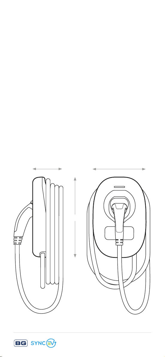
DIMENSIONS (MM) : 305 (H) x 201 (W) x 115 (D)
ADDITIONAL : ANTI TAMPER DETECTION - 2 LAYER
PROTECTION, BLUETOOTH TO
BLUETOOTH COMMISSIONING
ACCESSORIES : SINGLE CHARGER STAND
(EVASTAND12S)
TWIN CHARGER STAND
(EVASTAND12T)
CHARGING CABLES
COLOURED TRIMS
(VARIOUS OPTIONS, SEE SYNCEV.CO.UK)
115 mm
201 mm
305 mm
Return to Contents
Page 37

Technical support
Need help with the app?
Contact Monta customer support through the app
or via the website Monta.com
Need help with the charge-point?
Contact BG SyncEV technical support at:
or via the website at www.syncev.co.uk
BG SyncEV is a trading name of Luceco PLC.
Luceco PLC – Stafford Park 1, Telford, TF3 3BD,
England
(EU) Luceco SE – C/ Bobinadora 1-5, 08302
Mataro, Spain
Return to Contents
 Loading...