

Page 1

LPR Meter
Handbook
Page 2

CONTENTS
Section
Number
Page
Number
One Introduction Page 1
Two Major Components Page 2
Three Operating Instructions Page 3
Four Corrosion Rate Measurement Operation Page 6
Five LPR Standard Page 9
Page 3
1. Introduction
This handbook provides the Users Guide to the corrosion
rate monitoring handheld meter supplied by BGB Projects
Limited.
The meter has been designed to remove the complex nature
of corrosion rates by carrying out all of the calculations
internally.
The meter is supplied in a IP65 enclosure and is suitable for
external use.
The handheld meter equipment consist of the following
items:
• LPR Meter Part No. LPR174u
• Bigfoot Part No. BF225
• Ag/AgKCl(0.5M) Reference Electrode Part No. S100
All equipment is calibrated annually and calibration
certificates are available upon request.
LPR Meter Handbook Page 1
Page 4
2. Major Components
Handheld Meter
Bigfoot
Reference Electrode
Reinforcing Bar Connection
The following section outlines the major components of the
system with a detailed explanation to there use.
The handheld meter is the major component within the
system and carries out the Linear Polarisation test after
pressing a series of buttons.
The meter provides the following functions:
• Date & time
• Data logging up to 512 Readings
• PC Download Capability
• PT100 temperature Measurement
• LPR ID Reader (permanent probes only)
To carry out the corrosion rate measurement the big foot is
used to record the Corrosion potential (Ecorr) utilising the
reference electrode and pass a small current through the
integral Auxiliary electrode (AE).
The reference electrode is attached to the Big foot for
recording the corrosion potential from the reinforcing steel.
In carrying out the corrosion rate measurement the
handheld meter must be provided with a connection to the
reinforcing steel. This is carried out by either a single
connection (WE) if less than 10metres from the meter or by
two connections (WE & SENSE) for distances up to 30
metres.
NOTE: No testing should be carried out in excess of 30
metres and additional reinforcing steel connections are to be
made.
When using a single connection to the reinforcing steel the
supplied link must be installed between the WE and SENSE
terminals on the meter.
LPR Meter Handbook Page 2
Page 5
3. Operating Instructions
Set Up
The following section provides a step by step guide to the
operating instructions for the corrosion rate meter.
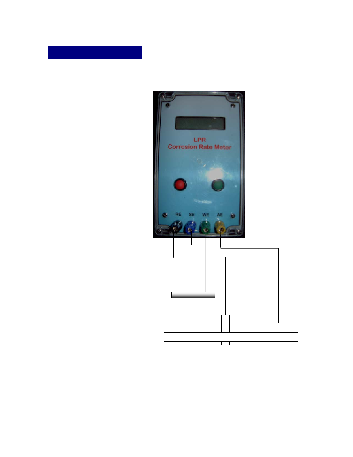
The above diagram provides the connections required to
carry out the corrosion rate measurement. Note that either
two connections are provided to the reinforcement or a
single connection is acceptable if less than 10metres. In this
application a link is required to interconnect the WE and SE
terminals on the meter.
Reinforcement
Reference Electrode
Big Foot
Auxiliary
Electrode
LPR Meter Handbook Page 3
Page 6

Connections
PC Communication
How to Use Meter
Charger Lead (5 pin plug):
Red +ve charger
Black -ve charger and RS485 ground
Yellow RS485 A
Blue RS485 B
ID Reader Lead (5 pin plug):
White ID chip
Black ID chip ground
Pt100 Lead (4 pin plug):
Red Pt100 sensor top
Black Pt100 sensor ground
RS485 Comms Protocol :
All comms at 9600, 8N1
When using a personal computer to access the meter please
install the supplied software. The software is supplied with
a separate manual and is not provided as standard please
consult manufacture for data logging software download.
Black is reference electrode (RE)
Blue is sense (short to Green if not used)
Green is test electrode (WE)
Yellow is auxilary electrode (AE)
Connect probe ID lead if used.
Connect Pt100 sensor lead if used.
• Power on.
• Meter displays its number, battery voltage and clock
setting.
• Meter then displays current reading slot number (eg.
01-006 is reading six on meter number one).
• Select GREEN button (LPR)
(RED button selects communications with computer)
• Meter reads Ecorr and probe ID number (if
connected).
• Select GREEN button (->)
(RED button aborts)
LPR Meter Handbook Page 4
Page 7

• Meter reads corrosion rate for 60 seconds (shown
on display)
(RED button pressed during the measurement skips
any remaining delay)
• Ecorr and corrosion rate are displayed
• Select EITHER button
• Meter confirms that data was stored
• Select GREEN button for next reading and repeat.
• RED button starts cycling through displays of stored
data as :
Date and Time
ID number
Ecorr
Epol
Corrosion rate
Temperature, Flags (Range, Measurement Time,
Errors)
Battery Voltage.
• Select RED button to exit data display.
• Power Off
LPR Meter Handbook Page 5
Page 8
4. Corrosion Rate
Measurement Operation
Introduction
Current Measurement
Autoranging
Overview
The LPR Handheld meter provides a complete corrosion rate
measurement system on a single Eurocard PCB.
Corrosion rate measurement is carried out potentiostatically,
using the three electrode linear polarisation resistance
measurement method.
The circuit samples the free corrosion potential of the test
electrode, applies a 20mV anodic polarisation and measures
the resulting polarisation current. This is directly
proportional to the corrosion rate of the test electrode.
The current measurement circuitry is fully autoranging and
the board is simply configured to take the measurement on
an instruction from the Main Control Unit.
Two outputs proportional to the polarisation current are
provided. The first is simply the output of the current
measuring amplifier. This varies during the time the
polarisation is applied to the test electrode, usually
approaching a steady state value after some 100 seconds or
more. At times when polarisation is not being applied to the
test electrode this output will be zero. The magnitude of
this output is simply equal to the polarisation current times
the range resistance.
The second output is proportional to the absolute value of
the polarisation current at the end of the polarisation period.
It is generated by a digital to analog converter and retains
its level during the ‘off’ (no polarisation applied) periods.
The value of this output represents the last polarisation
current measurement before the polarisation was removed
from the test electrode. The voltage of this output is equal
to the absolute value of the polarisation current times the
range resistance divided by two.
The polarisation current is measured as the voltage drop
across a resistance in the auxiliary electrode path. Some
+/- 12V are available at the output of the inbuilt potentiostat
for the test electrode polarisation, any voltage drop across
the current sensing resistor will reduce this amount
proportionally, in the extreme leading to a loss of
potentiostatic control of the test cell and erroneous
readings.
The autoranging circuitry is programmed to switch to the
next less sensitive range (lower measuring resistance) as
this voltage drop approaches some 3V and to switch to a
more sensitive range (larger resistance) as it decreases
below some 0.26V. In the autoranging mode the output of
the current measuring amplifier will therefore normally be
somewhere between these two limits. In certain situations
LPR Meter Handbook Page 6
Page 9

Δ
External Control Mode
Conversion of Reading to
Corrosion Rate
this output may move outside these limits to anywhere in
the +/- 15V range. Although the circuit is designed to
normally give a positive output, again, under certain
conditions, (test electrode potential drift etc) it may be
negative.
Since the second output is generated by a digital to analog
converter, it is somewhat more predictable, being always
the 0 to 2.048V range.
The Main Control Unit indicates the measurement by a logic
low input on the GO line. This causes the processor to
initiate the measurement and polarisation sequence.
Polarisation is then applied to the cell as long as the GO line
remains low. The RUN output is set high when the cell is
connected to the circuitry (RUN relay closed). The DONE
output is set high when the current measuring amplifier
output and the range indicator outputs are valid, it returns
low during any autoranging. The output of the current
measuring amplifier always reflects the current going to the
test electrode. The DAC2 output is set when the GO line is
released to high to reflect the cell current at that time.
The Outstation LPR board measures the current required to
polarise the test electrode anodically by 20mV. Conversion
to actual corrosion rate may be carried out as follows:
The voltage at the output of the current measuring amplifier
is the voltage drop across the current measuring resistor.
By Ohm’s law:
reading in mV/range = polarisation current in µA.
This is the applied current l
).
Δl
applied
The linear polarisation resistance measurement technique
(LPR) relies on a measurement of the slope of the current
vs. voltage response of the corroding interface at or near its
natural free corroding potential. It can be shown that this
slope, Δl
Stern-Geary equation:
/ΔE), is related to the corrosion current by the
applied
(or more accurately,
applied
LPR Meter Handbook Page 7
Δ
I
=
I
corr
Δ
where β
For practical purposes the equation can be simplified to:
corr
I =×
and βa are the cathodic and anodic Tafel slopes.
c
I
applied
=
E
Δ
×
E
b
⎛
1
⎜
⎜
3.2
⎝
B
p
R
⎞
ββ
acapplied
⎟
⎟
+
ac
ββ
⎠
Page 10

where B is an empirically determined constant and Rp is the
×
Δ
Δ
×
‘polarisation resistance’ of the corroding interface.
In order to calculate the actual penetration rate I
substituted to the Faraday equation, giving:
I
corr 1
npenetratio
time
××=
area
Thus, for example, to convert to cm/year for iron:
weightatomic
×
×
densityvalencyF
corr
is
ratenpenetratio
The PICLPR-2 board uses a 20mV anodic polarisation
applied potentiostatically to the test electrode. Hence ΔE is
0.02V, substituting in the above and solving gives:
ratenpenetratio
ratenpenetratio
B
R
p
BI
applied
=
×
area
02.0
I
applied
≅
×
/35
μ
×××××=
606024365
606024365
yearm
85.55
4
×××××
85.55
area
(l
in µA, area in cm², B=60mV)
applied
Or, using this board:
[]
μ
/
=
yearmratenpenetratio
×Ω
For example, a voltage of 1.00V at the DAC2 output on the
R1 range and using a 100cm² test electrode area is
equivalent to a penetration rate of:
35 x 1000 x 2 / 10 / 100 = 70µm/year
The nominal maximum measurable rate for this electrode
area, using the DAC2 output would be:
35 x 2047 x 2 / 1 / 100 = 1.4mm/year
and the minimum rate (assuming 20mV at DAC2 output):
35 x 20 x 2 / 100 / 100 = 0.14µm/year
1
×
××
87.7
210645.9
1
×
4
××
87.7
210645.9
][ 35
mVoutputamplifiercurrent
²][ ][
cmareasurfacerebarkrange
LPR Meter Handbook Page 8
Page 11
5. LPR Standard
LPR Meter Handbook Page 9
 Loading...