

Page 1
$12.00 U.S.
$12.00 U.S.
Pilot’s Guide
Pilot’s Guide
for the
for the
Traffic Alert/Advisory System
Traffic Alert/Advisory System
Model SKY899
Model SKY899
Preliminary
Page 2

Eyes That Never Blink
Early Traffic Alert/Advisory Systems
In the early days of flight, pilots were equipped with all they
needed for effective collision avoidance–a sharp pair of eyes.
But increasing traffic at higher speeds led to the development
TCAS I and II (Traffic Alert and Collision Avoidance Systems)
of
which were too expensive for most regional airlines, business
aircraft, and general aviation aircraft.
™
SKYWATCH
®
BFGoodrich Avionics Systems, Inc. recognized the need for an
alternative to expensive
SKYWATCH model SKY497 Traffic Advisory System (TAS) and
SKYWATCH HP model SKY899 TAS/TCAS I.
the
SKYWATCH HP can be installed as a TAS to provide most
The
of the capabilities of
making it practical for small aircraft. The
also be installed as a
In addition to its
upon the
range (
SKY497 by adding ADS-B surveillance, a larger display
15 nmi), and a higher maximum closure rate (1200 kn).
TCAS systems and developed the
TCAS I, but at a significantly lower cost,
SKYWATCH HP can
TCAS I.
TCAS I capability, SKYWATCH HP improves
Proven Experience
BFGoodrich Avionics Systems, Inc. has been involved in the
development of collision warning programs since the early
1980’s. In 1985, BFG began development of an enhanced
collision warning system for the
Based largely on the success of the
selected to validate the specifications for
Preliminary
BFG’s original TCAS I unit, the TCAS791 was the first TCAS I to
TSO’d, first to receive a full, unrestricted STC, first to fly,
be
and first to be delivered.
Navy’s T-34C training aircraft.
Navy project, BFG was
TCAS I. As a result,
A
SKY899 Pilot’s Guide
Page 3

$12.00 U.S.
Pilot’s Guide
for the
Traffic Alert/Advisory System
Model SKY899
Methods and apparatus disclosed and described herein have been developed solely on company funds of BFGoodrich Avionics Systems, Inc. No government or other contractual support or relationship whatsoever has
existed which in any way affects or mitigates proprietary rights of BFGoodrich Avionics Systems, Inc. in these
developments. Methods and apparatus disclosed herein may be subject to U.S. Patents existing or applied for.
BFGoodrich Avionics Systems, Inc. reserves the right to add, improve, modify, or withdraw functions, design
modifications, or products at any time without notice.
Preliminary
®
SKYWATCH
, EYES THAT NEVER BLINK™, and STORMSCOPE® are trademarks of
Designed and manufactured in the United States of America by
© Copyright 2001
BFGoodrich Avionics Systems, Inc.
BFGoodrich Avionics Systems, Inc.
BFGoodrich Avionics Systems, Inc.
5353 52nd Street, S.E.
Grand Rapids, MI 49512 USA
(800) 253-9525 or
Fax (616) 285-4224
www.bfgavionics.com
(616) 949-6600
Page 4
Safety Summary
These warnings and cautions appear later in this guide and are
repeated here for emphasis:
CAUTION
page 3-1
page 3-5
page 3-6
page 3-6
page 3-6
CAUTION
page 3-6
To avoid power surges that could damage the
optional
If the SKY899 is in SKYWATCH mode, the display will not automatically switch into Stormscope mode to display thunderstorms or
Stormscope errors. Use the remote SKYWATCH/Stormscope mode
switch to periodically check for thunderstorms or
The
nearby aircraft. The
are not equipped with an operating
Beacon System (ATCRBS) transponder.
The
closure rate greater than
Some traffic within the chosen display range may not be displayed
due to traffic prioritizing, antenna shielding, or ground intruder
filtering.
Optimum
are reporting their altitude (via a mode
reporting transponder).
WX-1000, start your engines before turning on the SKY899.
SKY899 relies on information obtained from transponders in
SKY899 does not detect or track aircraft which
Air Traffic Control Radar
SKY899 does not track intruder aircraft approaching at a
1200 knots.
SKY899 performance is realized when intruder aircraft
SKY899 and the
Stormscope errors.
C or other altitude
Do not attempt evasive maneuvers based solely on traffic informa-
page 3-6
ii
tion on the display. Information on the display is provided to the
flight crew as an aid in visually acquiring traffic; it is not a
replacement for
techniques.
Preliminary
Air Traffic Control (ATC) and See & Avoid
SKY899 Pilot’s Guide
Page 5

Section Page
Table of Contents
List of Illustrations ....................................... v
List of Tables ...............................................vi
Abbreviations & Acronyms ............................ vii
Chapter 1, System Description ................... 1-1
General Description ................................................................... 1-1
Transmitter Receiver Computer (TRC) ........................................ 1-2
Directional Antenna ................................................................... 1-2
Display ...................................................................................... 1-3
Interaction of Major Components ............................................... 1-4
Functional Description ............................................................... 1-4
Features ..................................................................................... 1-6
Chapter 2, Controls & Indicators ................. 2-1
Introduction .............................................................................. 2-1
Controls, Indicators, & Symbols ................................................. 2-1
Controls Required for the Stormscope Option ............................... 2-5
Controls & Indicators for an Alternate Display ............................. 2-6
Aural Announcements ................................................................ 2-6
Chapter 3, Operating Instructions ............... 3-1
Introduction .............................................................................. 3-1
Turn On the SKY899 ................................................................. 3-1
Run the Operator-Initiated Self Test ............................................ 3-3
Switch Between Standby & Normal Operating Mode ................... 3-3
Change the Display Range .......................................................... 3-4
Change the Vertical Display Mode ............................................... 3-5
Switch Between SKYWATCH & Stormscope .................................. 3-5
Preliminary
Observe the Display ................................................................... 3-6
Respond to Traffic Advisories ...................................................... 3-6
Turn Off the SKY899 and the Optional WX-1000 ....................... 3-7
Operate the WX-1000 Without the SKY899 ............................... 3-7
Operate the SKY899 Without the WX-1000 ............................... 3-7
Message Response ...................................................................... 3-7
Respond to a Failed System.................................................... 3-7
Respond to a Degraded System .............................................. 3-9
SKY899 Pilot’s Guide
iii
Page 6

Table of Contents (continued)
Section Page
Chapter 4, Principles of Operation ............... 4-1
Introduction .............................................................................. 4-1
Sensitivity Levels ........................................................................ 4-1
Sensitivity Level A ................................................................. 4-1
Sensitivity Level B ................................................................. 4-3
Audio Inhibit, SKY899 ............................................................... 4-5
Audio Inhibit, GPWS, EGPWS, or TAWS ................................... 4-5
TA Symbol Duration .................................................................. 4-6
Ground Intruder Filtering ........................................................... 4-6
ADS-B ...................................................................................... 4-6
Chapter 5, Display Interpretation ................ 5-1
Introduction .............................................................................. 5-1
Chapter 6, Specifications ........................... 6-1
Chapter 7, Warranty Information ................ 7-1
Introduction .............................................................................. 7-1
Warranty Statement.................................................................... 7-1
Related Policies and Procedures ................................................... 7-2
Preliminary
iv
SKY899 Pilot’s Guide
Page 7

List of Illustrations
Figure Title Page
1-1 SKY899 Major Components .............................................................. 1-1
1-2 Display with Typical SKYWATCH HP Screen .................................... 1-3
1-3 Display with Typical Stormscope Screen (Optional) ............................. 1-3
1-4 System Block Diagram ....................................................................... 1-5
1-5 Vertical Display Modes and Traffic Zones ............................................ 1-7
2-1 Controls & Screen Elements in Standby .............................................. 2-1
2-2 Controls & Screen Elements in Operating Mode ................................. 2-2
2-3 Vertical Display Mode Indicator Lamps ............................................... 2-6
3-1 BFGoodrich Screen ........................................................................... 3-1
3-2 Standby Screen .................................................................................. 3-2
3-3 In-Flight Traffic Screen ....................................................................... 3-2
3-4 Failed Screen ..................................................................................... 3-2
3-5 Test Screen ........................................................................................ 3-3
3-6 Traffic Screen on the Ground.............................................................. 3-4
3-7 Display Ranges .................................................................................. 3-4
3-8 Message Screen with Two Messages ..................................................... 3-9
3-9 Message Screen with No Messages .................................................... 3-10
4-1 TA Zones If Your Aircraft Has a Radio Altimeter .................................. 4-4
4-2 TA Zones If Your Aircraft Has No Radio Altimeter, But Does Have a
Retractable Landing Gear ................................................................... 4-4
4-3 TA Zones If Your Aircraft Has No Radio Altimeter
and a Fixed Landing Gear................................................................... 4-5
4-4 ADS-B ............................................................................................. 4-6
5-1 TA & OT on 15 nmi Range, UNR Mode ........................................... 5-1
5-2 Other Traffic on 15 nmi Range, UNR Mode ....................................... 5-2
5-3 Other Traffic on 6 nmi Range, NRM Mode......................................... 5-2
5-4 TA & OT on 2 nmi Range, BLW Mode .............................................. 5-2
5-5 Off-Screen TA on 2 nmi Range, ABV Mode ........................................ 5-3
Preliminary
5-6 Standby Screen .................................................................................. 5-3
5-7 Failed Screen ..................................................................................... 5-3
SKY899 Pilot’s Guide
v
Page 8

List of Tables
Table Title Page
4-1 Fourteen Situations in Which a Traffic Advisory Will Occur ................. 4-2
6-1 TRC899 Specifications ...................................................................... 6-1
6-2 BFG WX-1000/SKY497 Display Specifications .................................. 6-3
6-3 NY164 Directional Antenna Specifications
(for TAS installations only) ................................................................. 6-4
6-4 NY156 Directional Antenna Specifications
(
required for TCAS I installations, optional for TAS
)............................... 6-4
Preliminary
vi
SKY899 Pilot’s Guide
Page 9

Abbreviations & Acronyms
ABV Above
Ack Acknowledge
ADS-B Automatic Dependent Surveillance-Broadcast
AFM Aircraft Flight Manual
AFS Flight Standards Service
AGL Above Ground Level
AHRS Attitude and Heading Reference System
Alt Altitude
ARINC Aeronautical Radio, Inc.
ATC Air Traffic Control
ATCRBS Air Traffic Control Radar Beacon System
ATI Air Transport Indicator
ATM Air Traffic Management
BFG BFGoodrich
BFGAS BFGoodrich Avionics Systems, Inc.
BLW Below
Comm Communication
CPA Closest Point of Approach
CRT Cathode Ray Tube
EFIS Electronic Flight Instrument System
EGPWS Enhanced Ground Proximity Warning System
FAA Federal Aviation Administration
fpm Feet Per Minute
FSAW Flight Standards Information Bulletin for
Airworthiness
GPS Global Positioning System
GPWS Ground Proximity Warning System
Preliminary
Grnd Ground
HP High Performance
I/O Input/Output
IVSI Instantaneous Vertical Speed Indicator
kn Knots
MFD Multi-Function Display
Mod Modification
SKY899 Pilot’s Guide
vii
Page 10

Abbreviations & Acronyms (continued)
MSG Message
Nav Navigation
nm Nautical Miles (on the display)
nmi Nautical Miles (in the text)
NRM Normal
OPR Operate
OT Other Traffic
PA Proximity Advisory
P/N Part Number
Rev Revision
RGC Radar Graphics Computer
RTCA Requirements & Technical Concepts for Aviation
SLA Sensitivity Level A
SLB Sensitivity Level B
SSR Secondary Surveillance Radar
STB Standby
TA Traffic Advisory
TAS Traffic Advisory System
TAWS Terrain Awareness and Warning System
TCAS Traffic Alert and Collision Avoidance System
TRC Transmitter Receiver Computer
TSO Technical Standard Order
UNR Unrestricted
Preliminary
viii
SKY899 Pilot’s Guide
Page 11
Chapter 1
System Description
General Description
The SKYWATCH
SKY899, from BFGoodrich Avionics Systems, Inc. (BFG) can be
installed as a
(TCAS I) or as a Traffic Advisory System (TAS). In either
configuration, the
aircraft and advises the flight crew where to look for transponder-equipped aircraft that may pose a collision threat. Traffic
information on the display generally includes the range, relative
bearing, and relative altitude of intruder aircraft. The
also makes aural announcements such as traffic advisories on
the cockpit audio system. The
high performance corporate and general aviation aircraft.
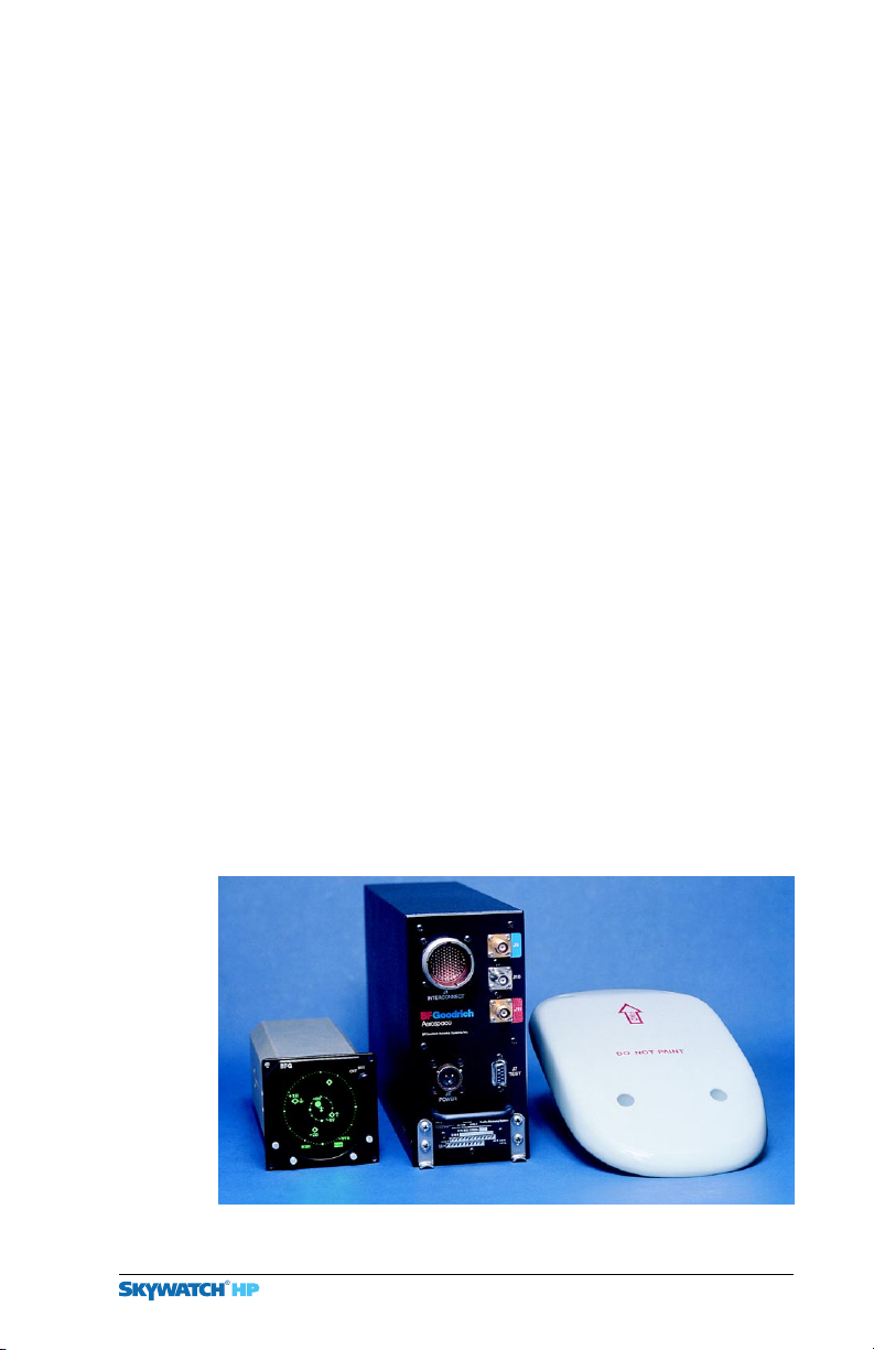
1-1 shows the major components of the SKY899.
Figure
®
HP Traffic Alert/Advisory System, model
Traffic Alert and Collision Avoidance System I
SKY899 monitors the airspace around your
SKY899
SKY899 is intended for use by
This is the SKY497
picture. I will substitute
a picture of the SKY899
when the equipment is
ready to photograph.
Preliminary
Display
Figure 1-1. SKY899 Major Components
SKY899 Pilot’s Guide 1-1
TRC
Directional Antenna
Page 12

TRC & Antenna
When installed as a TAS, the SKY899 can share a BFG model
WX-1000/SKY497 monochrome display (P/N 78-8060-5900-8 or 9
) with a BFG STORMSCOPE® model WX-1000 using a remote
SKYWATCH/Stormscope mode switch. As a TAS, the SKY899 can
also display traffic on a growing number of
Displays (MFDs) and Electronic Flight Instrument System
EFIS) displays from companies such as Avidyne, Garmin, and
(
Collins, or on select Instantaneous Vertical Speed Indicators
IVSIs) from Honeywell or Sextant, or on a compatible weather
(
radar indicator via the
RGC250. Check with your dealer or with BFG for a current list
of approved alternate displays.
Chapter 1 – System Description
Multi-Function
BFG Radar Graphics Computer, model
When installed as a
information on a
scribed above, but not on the
Hereafter the word display refers to the
display unless otherwise indicated. For any other display, refer
to that display’s manual for a description of how it displays
SKY899 traffic information.
TCAS I, the SKY899 displays its traffic
TCAS I-compatible alternate display as de-
WX-1000/SKY497 display.
WX-1000/SKY497
Transmitter Receiver Computer (TRC)
The TRC is the primary unit of the SKY899. It converts signals
from the directional antenna and from other aircraft systems
into an on-screen picture of intruder aircraft locations, and if
necessary, aural traffic advisories. The
intruder aircraft simultaneously, but to reduce clutter, the
SKY899 only displays the 8 most threatening intruders being
tracked. The
faults and to verify proper operation.
TRC also has built-in test equipment to detect
TRC can track up to 35
Directional Antenna
The directional antenna transmits omnidirectional mode C
interrogations and receives directional replies from other
Preliminary
transponder-equipped aircraft in the vicinity. The antenna also
receives
mode
Automatic Dependent Surveillance-Broadcast (ADS-B)
S extended squitter broadcasts from intruder aircraft.
1-2
SKY899 Pilot’s Guide
Page 13
Chapter 1 – System Description
Display
The display is a 3-inch Air Transport Indicator (3-ATI) unit
with a high resolution, green monochrome
CRT) display. The bezel contains four momentary contact
(
push-button switches and an on/off/brightness knob. The
display provides control and display functions for the
(installed as a TAS) and for a WX-1000 Stormscope (if installed).
The display does not display traffic and storm information
simultaneously. The position of a remote
S
tormscope mode switch determines whether the display shows
traffic or storm information; however, if you’re in
mode and the
ate threat to your aircraft, the display temporarily switches to
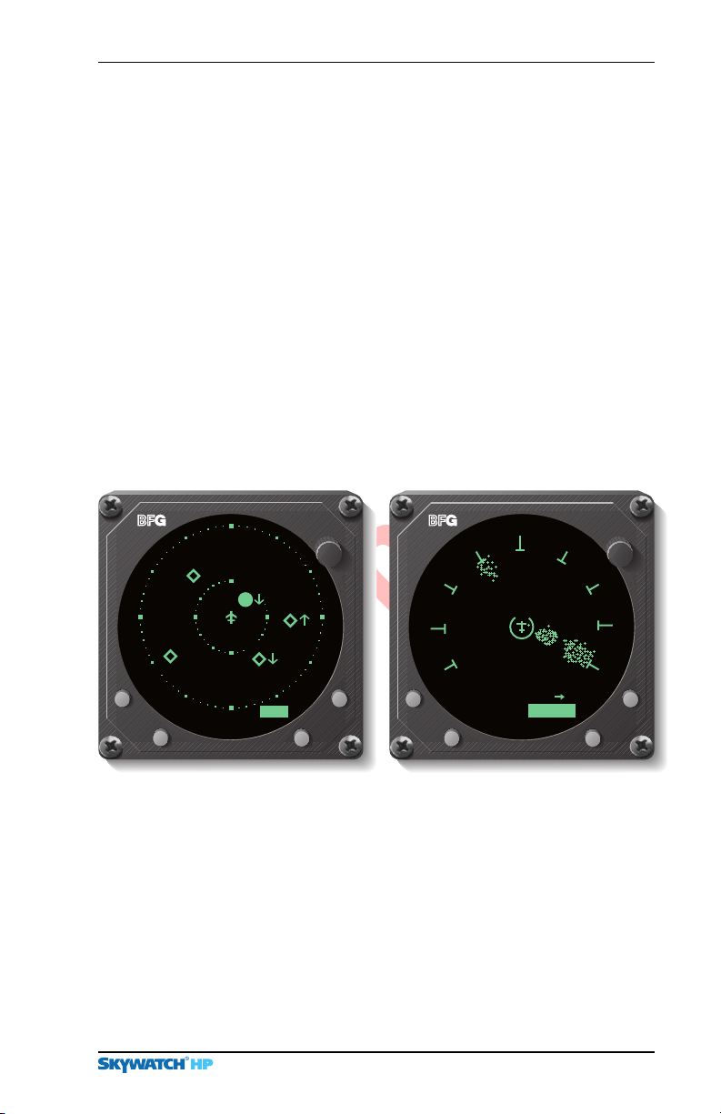
SKYWATCH mode. Figure 1-2 shows the display with a typical
SKYWATCH HP screen. Figure 1-3 shows the display with a
typical
SKY899 detects traffic that may pose an immedi-
Stormscope screen.
Display
Cathode Ray Tube
SKY899
SKYWATCH/
Stormscope
BRT
OFF
+03
-07
+80
-35
nm
UNR
15
Figure 1-2. Display with Typical
SKYWATCH HP Screen
25
MENU
CLEAR
200 nm
Figure 1-3. Display with Typical
Stormscope Screen (Optional)
120°
OFF
BRT
Preliminary
SKY899 Pilot’s Guide
1-3
Page 14

Interaction of Major Components
Chapter 1 – System Description
Interaction of Major Components
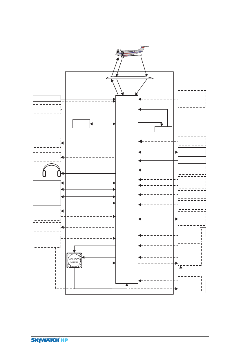
Figure 1-4 shows how the major components of the SKY899
connect to each other and to other aircraft systems.
Notes on Figure 1-4:
1. The optional radio altitude input affects the
inhibit feature, the ground intruder filtering feature, and
the sensitivity levels feature. (See chapter
2. GPS nav data is only required if you plan on using
SKY899’s ADS-B feature (for intruder location enhance-
ment).
3. The
4. Having a weight-on-wheels input allows the
5. The
6. The RGC250/radar indicator or alternate display can be in
7. Only required when using an alternate display that doesn’t
SKY899 works without a heading input, but experi-
ences degraded performance during high-rate-of-turn
maneuvers.
automatically switch out of standby when you take off,
and into standby when you land.
SKY899 may be installed on aircraft with fixed landing
gear. The optional landing gear position input affects the
sensitivity levels feature. (See chapter
place of, or in addition to the
TAS installations, but one of the two must be used for
TCAS I installations.
display vertical display mode indications.
WX-1000/SKY497 display for
SKY899 audio
4 for details.)
SKY899 to
4 for details.)
Functional Description
The SKY899 is an active system that operates as an aircraft-toaircraft interrogation device. The
transponders in the surrounding airspace (within a
horizontal radius) similar to the way ground-based radar
interrogates aircraft transponders. When the
Preliminary
replies to its interrogations, it computes the responding
aircraft’s range, relative bearing, relative altitude, and closure
rate. The
responding aircraft and uses that information along with your
own aircraft
data to enhance the computed relative position of the respond-
1-4
SKY899 also receives any ADS-B broadcasts from the
Global Positioning System (GPS) navigation (nav)
SKY899 interrogates aircraft
35 nmi
SKY899 receives
SKY899 Pilot’s Guide
Page 15
Chapter 1 – System Description
System Block Diagram
Intruder Aircraft
Transponder
Interrogations
Directional
Antenna
Transponder
Interrogations
Barometric Altitude
Configuration
Plug
Discrete Lamp Control
Indicator Lamp Outputs
Settings
ABV & BLW
Display (ARINC 429)
Control (ARINC 429)
Display (ARINC 429)
SKYWATCH
Control
Display Power
SKYWATCH-
Stormscope
SKYWATCH-
Stormscope
TAS o r
Control
Encoding Altimeter
Air Data Computer
(Optional)
Operate Lamp
(Optional)
ABV & BLW
Indicator Lamps
Aircraft
Audio
System
Future
Enhancements
BFG RGC250/
Radar Indicator
6
(Optional)
Alternate Display
Control Panel for
use with Alternate
Display (Optional)
(Optional)
6
SKY899
Personality
7
Aural TA's & Other Audio Output
Bi-directional Discrete I/O
Auxiliary Serial Data (RS-422)
Auxiliary Serial Data (RS-232)
Auxiliary ARINC 429 RX Data
SKYWATCH
SKYWATCH
SKYWATCH
WX-1000
Display
Preliminary
On/Off Control
TAS o r
Display
Transponder
Replies
Transponder
Replies
TRC
(with Option)
ADS-B Squitter
Broadcasts
ADS-B Squitter
Broadcasts
Radio Altitude
System Software
Updates
Flight Data
&System
Configuration
GPS Nav Data
(ARINC 429)
TX/RX Inhibit
+28 V dc
Audio Inhibit
Magnetic Heading
Mag. Heading Valid
Weight On Wheels
Landing
Gear Position
Diagnostic
Commands and
Status (RS-232)
SKYWATCH/
Stormscope
Mode Selection
TRC On/Off Control
Stormscope
Stormscope
TRC On/Off Control
When WX-1000 is
Powered Down or
Removed
On/Off Control
Stormscope
1
Flash Card
2
5
Display
Control
Override
Radio Altimeter or
3
4
Norm
Flight Data
Computer
(Optional)
GPS Navigation
System (Optional)
Aircraft
Suppression Bus
Aircraft Power
GPWS/TAWS
(Optional)
Synchro XYZ
Compass, or
AHRS (Optional)
Squat Switch
(Optional)
Landing Gear
Switch (Optional)
Diagnostic
Equipment e.g.
Laptop (Optional)
SKYWATCH/
Stormscope
Mode Switch
WX-1000
Stormscope
Processor
WX-1000
On/Off Control
WX-1000
Maintenance
Switch
Option
Stormscope
Figure 1-4. System Block Diagram
SKY899 Pilot’s Guide
1-5
Page 16

Features
Chapter 1 – System Description
ing aircraft. The SKY899 then predicts collision threats and
plots the eight most threatening aircraft locations on the
display.
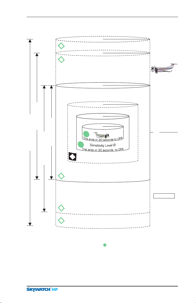
1-5 shows the SKY899 vertical display modes (look up,
Figure
look down, normal, and unrestricted). The figure also shows
the traffic zones around your aircraft and the traffic symbols
that appear on the display when intruding aircraft enter one of
those zones.
A solid circle is the visual part of the
the
may pose a collision threat. The aural part of the
traffic,” is annunciated over a cockpit speaker or headset. An
open diamond represents
an immediate collision threat. A solid diamond (
Advisory, PA) only appears on TCAS installations.
The
Level B (SLB) to determine when to display a TA. In general,
SLB is used during the in-flight phase and SLA is used during
takeoff and landing. Sensitivity levels and other factors affecting the display of traffic symbols are discussed in detail in
chapter
Features
• Tracks up to 35 intruder aircraft (displays the 8 most threat-
• Tracks intruder aircraft approaching at closure rates up to
• Installs as a
• Costs only a fraction of the price of a traditional TCAS I or II
Traffic Advisory (TA) that
SKY899 generates when it predicts that an intruder aircraft
TA, “traffic,
Other Traffic (OT) that does not pose
Proximity
SKY899 uses either Sensitivity Level A (SLA) or Sensitivity
4.
ening)
1200 knots
TAS or as a TCAS I
• Requires no mode S transponder
• Displays traffic information in three horizontal display
Preliminary
ranges:
• Displays traffic information in four vertical display modes:
normal (
(
• Generates visual and aural advisories of aircraft that may pose
a collision threat
1-6
15, 6, and 2 nmi
±2,700 ft), look up (+9,000 ft to –2,700 ft), look down
+2,700 ft to –9,000 ft), and unrestricted (±9,900 ft)
SKY899 Pilot’s Guide
Page 17
Chapter 1 – System Description
(OT)
(OT)
15 nmi
15 nmi
15 nmi
Traffic Zones Diagram
+9900 ft
+9900 ft
+9000 ft
Intruder Aircraft
Look Up (ABV)
15 nmi
4 nmi
0.55 nmi
0.2 nmi
S
e
n
s
i
t
i
A
l
e
v
e
v
L
ity
*
+2700 ft
+1200 ft
+800 ft
+600 ft
0 ft
–600 ft
Normal (NRM)
Unrestricted (UNR)
(
P
A
–
o
n
T
C
A
S
o
*
*
nly
)
Look Down (BLW)
(
O
T
)
(
O
T
)
(
O
T
)
*15 seconds for non-altitude reporti ng intruder aircraft
Preliminary
**20 seconds for non-altitude reporti ng intruder aircraft
CPA – Closest Point of Approach PA – Proximity Advisory
OT – Other Traffic
Refer to chapter 4 for details.
– Traffic Advisory
–800 ft
–1200 ft
–2700 ft
Not To Scale
–9000 ft
–9900 ft
Figure 1-5. Vertical Display Modes and Traffic Zones
SKY899 Pilot’s Guide
1-7
Page 18

Features
Features – Continued
• Performs automatic and operator-initiated self tests
Chapter 1 – System Description
• Offers a high-resolution, green monochrome,
TAS installations
• Transmits interrogations from the ground (if desired) as well
as from the air
• Shares a display with the
when the
• Switches to the SKYWATCH screen from the optional
Stormscope screen automatically when a TA occurs
• Uses only one antenna
• Eases installation since the standard
cutout in the cockpit panel
• Displays traffic on a variety of displays
• Uses information from
with own aircraft
computation
SKY899 is installed as a TAS
GPS nav data to enhance intruder location
Stormscope WX-1000 (if desired)
TAS display fits in a 3-ATI
ADS-B broadcasts (if available) along
CRT display for
Preliminary
1-8
SKY899 Pilot’s Guide
Page 19
Chapter 2
Controls &
Indicators
Introduction
This chapter describes the SKY899 controls and indicators
including the controls, indicators, and symbols on the display,
discrete controls and indicators, and aural announcements.
Controls, Indicators, & Symbols
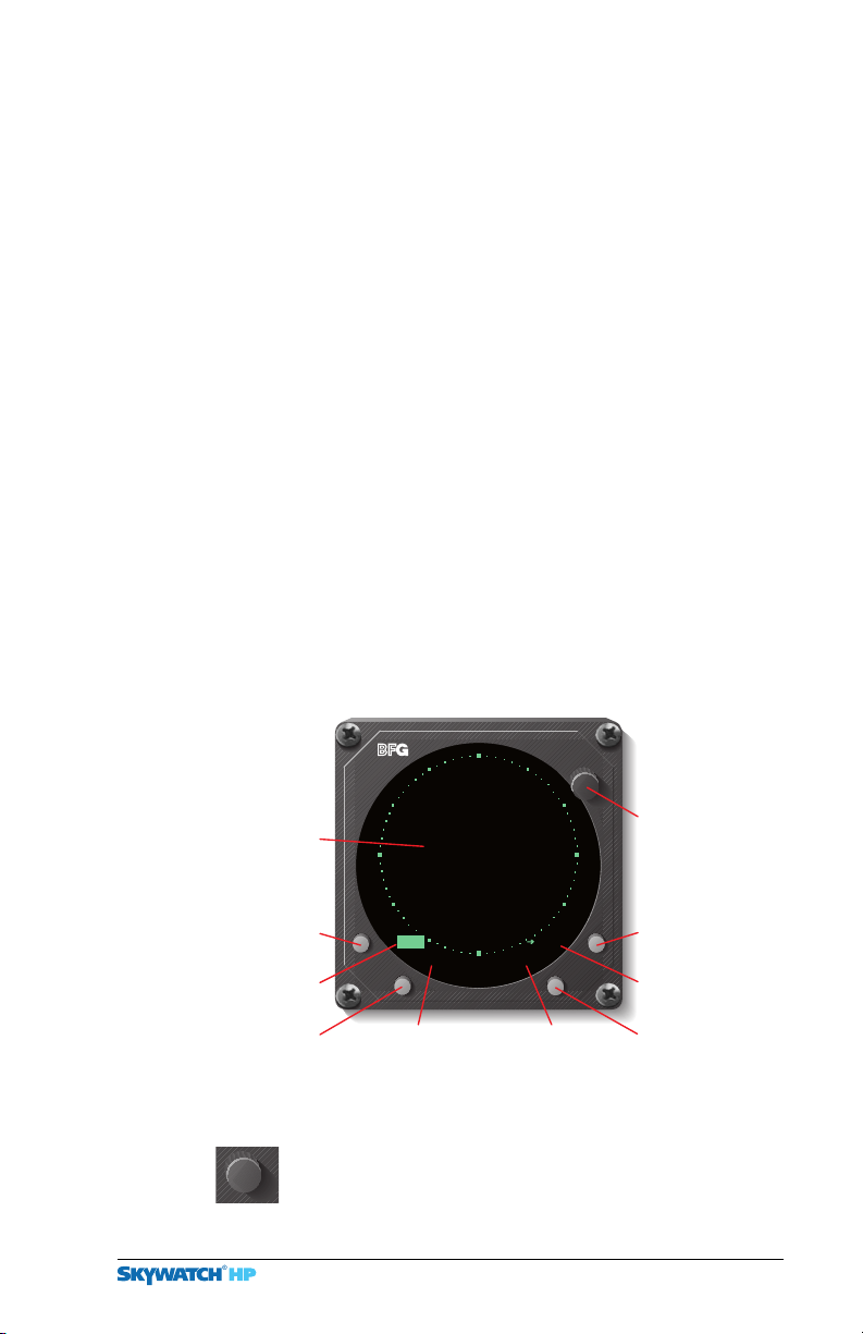
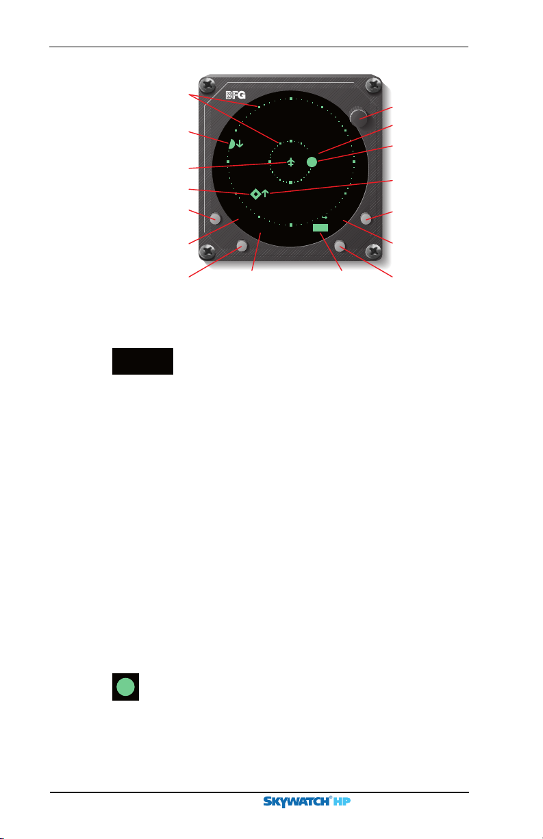
Figures 2-1 and 2-2 and the following paragraphs describe the
SKY899 controls, indicators, and symbols.
BRT
OFF
Standby
Indicator
Message
Button
Message
Indicator
Test
Preliminary
Button
Figure 2-1. Controls & Screen Elements in Standby
Power/Brightness Control Knob (OFF/BRT)
This knob controls power to the
(if installed) and adjusts display brightness.
SKY899 Pilot’s Guide 2-1
SKY899
Standby
TEST
Label for
Test Button
OPRMSG
nm
6
Display Range
Indicator
Power/
Brightness
Control Knob
Operating
Mode Button
Label for Op
Mode Button
Display Range
Button
SKY899 and WX-1000
Page 20
On-Screen Elements
Chapter 2 – Controls & Indicators
Range
Rings
Off-Screen
Tra f f ic
Advisory (
Own Aircraft
Other Traffic
Display Mode
TA)
Message
Button
Message
Indicator
Ver tica l
Button
+05
+10
UNR
Ver tica l
Display Mode
Indicator
+04
nm
6
Display
Range
Indicator
BRT
OFF
STBMSG
Power/
Brightness
Control Knob
Data Tag
Tra f f ic
Advisory (TA)
Ver tica l
Trend Arrow
Operating
Mode Button
Label for Op
Mode Button
Display
Range
Button
Figure 2-2. Controls & Screen Elements in Operating Mode
Data Tag These two digits indicate, in hun-
+04
dreds of feet, the relative altitude of the intruder
aircraft. In this case, +
aircraft is
400 feet above you. A positive data tag is
04 means the intruder
displayed above the traffic symbol to emphasize
that the intruder aircraft is above your aircraft.
Similarly, a negative data tag is displayed below
the traffic symbol. If the intruder is at the same
altitude as your aircraft,
00 is displayed above the
traffic symbol.
The data tag for a vertically out of range
TA stays
at the maximum or minimum relative altitude
number of the current vertical display mode until
the intruder aircraft comes within the relative
altitude limits of the vertical display mode. The
SKY899 only displays data tags for altitude report-
ing aircraft. Non-altitude-reporting aircraft are
Preliminary
considered to be at the same altitude as your awn
aircraft.
2-2
Traffic Advisory (TA) A
TA consists of a symbol on-
screen and a “traffic, traffic” message on the cockpit
speakers or headset. When an intruder aircraft that meets
TA criteria described in chapter 4 is within the
the
displayed range (inside or outside of the selected vertical
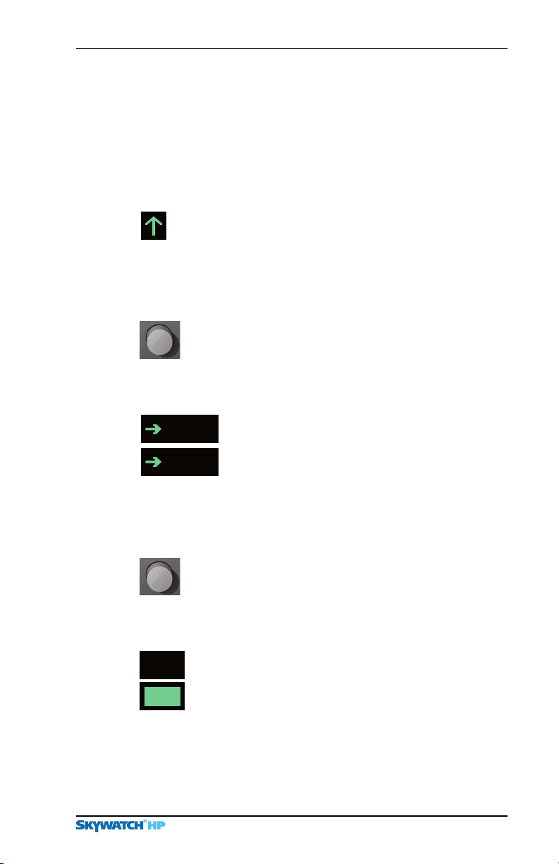
display mode), the corresponding symbol is this circle
SKY899 Pilot’s Guide
Page 21
Chapter 2 – Controls & Indicators
located at a position on the screen that indicates the
relative bearing and range of the intruder aircraft.
Buttons & On-Screen Elements
In general, the
intruder aircraft within
or within a
relative altitude range of your aircraft. (See chapter
details.)
Vertical Trend Arrow A vertical trend arrow
indicates that the intruder aircraft is ascending (up
arrow) or descending (down arrow) faster than
No arrow is shown for intruder aircraft in level flight, or
for those moving vertically slower than
non-altitude-reporting intruder aircraft.
Operating Mode Button Pressing this button
when it’s labeled
normal operating mode and into standby. Pressing the
button when it’s labeled
out of standby and into normal operating mode.
STB
OPR
SKY899 issues a TA when it detects an
30 seconds of a possible collision,
0.55 nmi horizontal radius and a ±800 ft
500 fpm.
500 fpm, or for
STB switches the SKY899 out of
>
OPR switches the SKY899
>
Label for Operating Mode Button This
on-screen label identifies the function of the
adjacent button. The
traffic screen and means go to standby. The
OPR label appears on the standby screen and
>
means go to normal operating mode. If your
aircraft has a squat switch, the
appears when your aircraft is on the ground.
STB label appears on the
>
STB label only
>
4 for
Display Range Button Pressing this button when
SKY899 is in standby has no effect. Pressing the
the
button when the
SKY899 display range between 15, 6, and 2 nmi as
the
reflected in the on-screen display range indicator.
Preliminary
6
6
Display Range Indicator The unhighlighted
nm
version of the indicator (present only on the
screen) simply reminds you that the adjacent button
nm
can be used to select the display range once you
switch into operating mode. The highlighted version
of the indicator (present only in operating mode)
identifies the currently selected display range (
2 nmi).
SKY899 Pilot’s Guide
SKY899 is in operating mode toggles
Standby
15, 6, or
2-3
Page 22
Buttons & On-Screen Elements
Chapter 2 – Controls & Indicators
UNR
Vertical Display Mode Button/Test Button
In operating mode, this button changes the
vertical display mode between above, normal, below,
and unrestricted as reflected in the on-screen vertical
display mode indicator. In standby, this button starts a
self test.
TEST
MSG
MSG
Vertical Display Mode Indicator This
indicator displays the name of the currently
selected vertical display mode:
BLW (below/look down), NRM (normal), or
up),
UNR (unrestricted). The indicator does not appear
when the
Message Indicator The highlighted version
of this indicator appears when there is a new
message. The indicator switches to the
unhighlighted version when all the messages have
been read. In operating and failed modes, the
unhighlighted version disappears when the
messages disappear, but in standby, the
unhighlighted version remains on the screen even
if there are no messages.
SKY899 is in standby.
Label for Test Button This on-screen
label only appears when the
standby or in failed mode. It identifies the
function of the adjacent button which is to start
the operator-initiated self test.
ABV (above/look
SKY899
SKY899 is in
Message Button When the message indicator is
present, pressing this button displays the message
screen.
Other Traffic (OT) On the
this symbol represents an intruder aircraft that has been
Preliminary
2-4
detected within the selected display range and vertical
display mode, but which has not generated a
alternate displays, this symbol represents an intruder
aircraft that has been detected within the selected display
range and vertical display mode, but which does not
generate a
Proximity Advisory (PA) (not shown) This
symbol only appears on
TA or a PA.
WX-1000/SKY497 display,
TA. On
TCAS installations. A PA
SKY899 Pilot’s Guide
Page 23
Chapter 2 – Controls & Indicators
represents an intruder aircraft that does not generate a
TA, but which is within a horizontal range of 4 nmi and
a relative altitude of ±
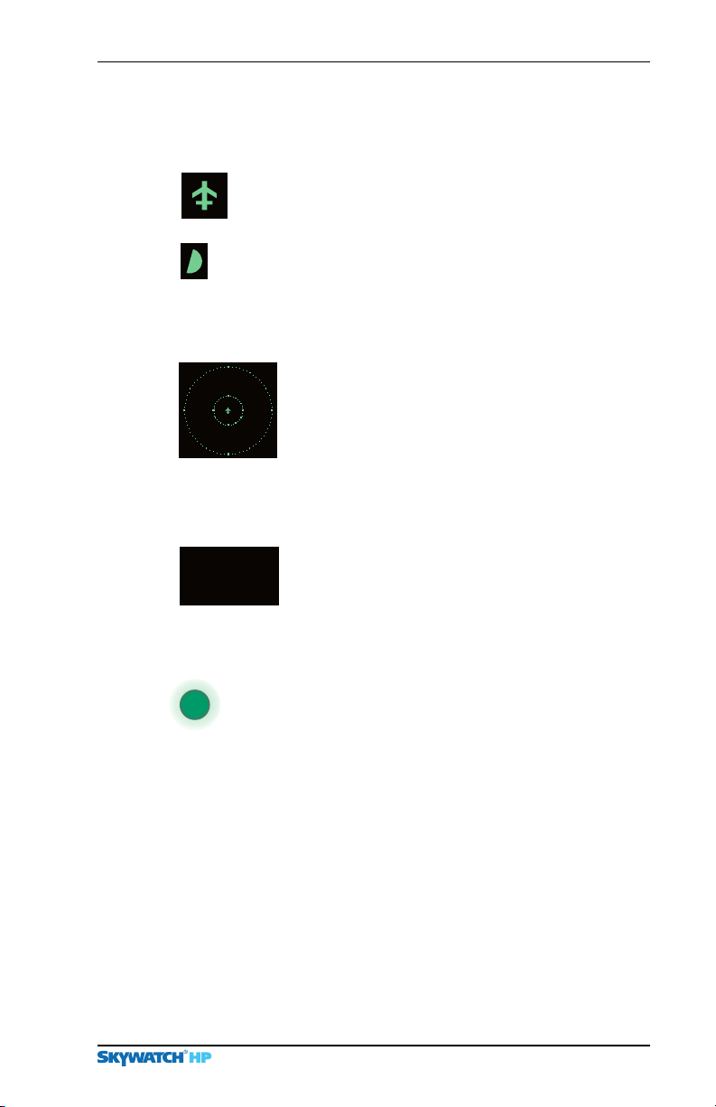
Own Aircraft This symbol represents your aircraft’s
relative position and heading.
Off-Screen Traffic Advisory (TA) This symbol
represents a
current display range. The symbol is displayed at a
position along the outer range ring that indicates the
relative bearing of the intruder aircraft.
TA that has been detected beyond the
Range Rings The outer range ring represents
a distance of
corresponding to the selected display range as
indicated in the display range indicator. The
inner range ring on the
a distance of
6 nmi range represents a distance of 2 nmi.
There is no inner range ring on the
for Stormscope
1200 ft.
15, 6, or 2 nmi from your aircraft
15 nmi range represents
6 nmi. The inner range ring on the
2 nmi range.
SKY899
Standby
Operate Lamp (optional, not supplied) This
panel-mounted indicator light is lit whenever the
is sending out interrogations. The light is not lit in
standby or when the unit is in failed mode.
Controls Required for the
Preliminary
SKYWATCH/
This panel-mounted toggle switch determines whether traffic
information or thunderstorm information is displayed.
SKY899 and the WX-1000 continue tracking even if the
The
switch is in the other position. If the
generates an error message when the switch is in the
position, the display switches to the traffic screen to display the
TA or the error message.
SKY899 Pilot’s Guide
Standby Indicator This indicator is
displayed as long as the
except when the test screen is displayed during
an operator-initiated self test. In standby, the
SKY899 does not interrogate, process, or display
traffic.
Stormscope
Stormscope
SKY899 is in standby
SKY899
Option
Mode Switch (not supplied)
SKY899 detects a TA or
Stormscope
2-5
Page 24
Alternate Display & Aural Announcements
WX-1000 Maintenance Switch (not supplied) This
remote toggle switch (normally installed in the avionics bay
near the
Override (WX-1000 maintenance) position. It should only be
moved to the
removed or powered down at the circuit breaker, and you still
want to use the
WX-1000 processor) has a Normal position and an
Override position when the WX-1000 processor is
SKY899.
Chapter 2 – Controls & Indicators
Controls & Indicators for an Alternate Display
Control Panel (not supplied) A discrete control panel pro-
vides the functions normally provided by the buttons and knob
WX-1000/SKY497 display. These functions include
on the
controlling power to the
selecting the vertical display mode, selecting the operating
mode, and starting the self test.
SKY899, selecting the display range,
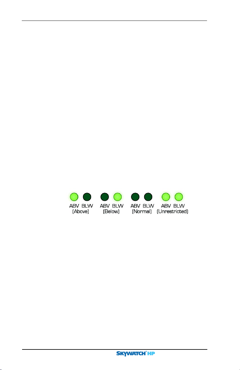
Vertical Display Mode Indicator Lamps
Some alternate displays do not display a vertical display mode
indicator on-screen. For those displays, two discrete indicator
lamps similar to those shown in figure
vertical display mode.
Figure 2-3. Vertical Display Mode Indicator Lamps
2-3 indicate the current
(not supplied)
Aural Announcements
“Traffic, Traffic” This aural component of a traffic advisory
is announced once over the cockpit speakers or headset when a
TA is first detected.
“SKYWATCH System Test Passed” This message is
announced once over the cockpit speakers or headset after the
Preliminary
SKY899 has passed an operator-initiated self test.
“SKYWATCH System Test Failed” This message is
announced once over the cockpit speakers or headset after the
SKY899 has failed an operator-initiated self test.
2-6
SKY899 Pilot’s Guide
Page 25
Introduction
This chapter lists the SKY899 operating instructions and
describes its fault modes.
Turn On the SKY899
Chapter 3
Operating
Instructions
CAUTION
To avoid power surges that could damage the SKY899 and the
optional
1. Turn the
Preliminary
WX-1000, start your engines before turning on the SKY899.
OFF/BRT
brightness.
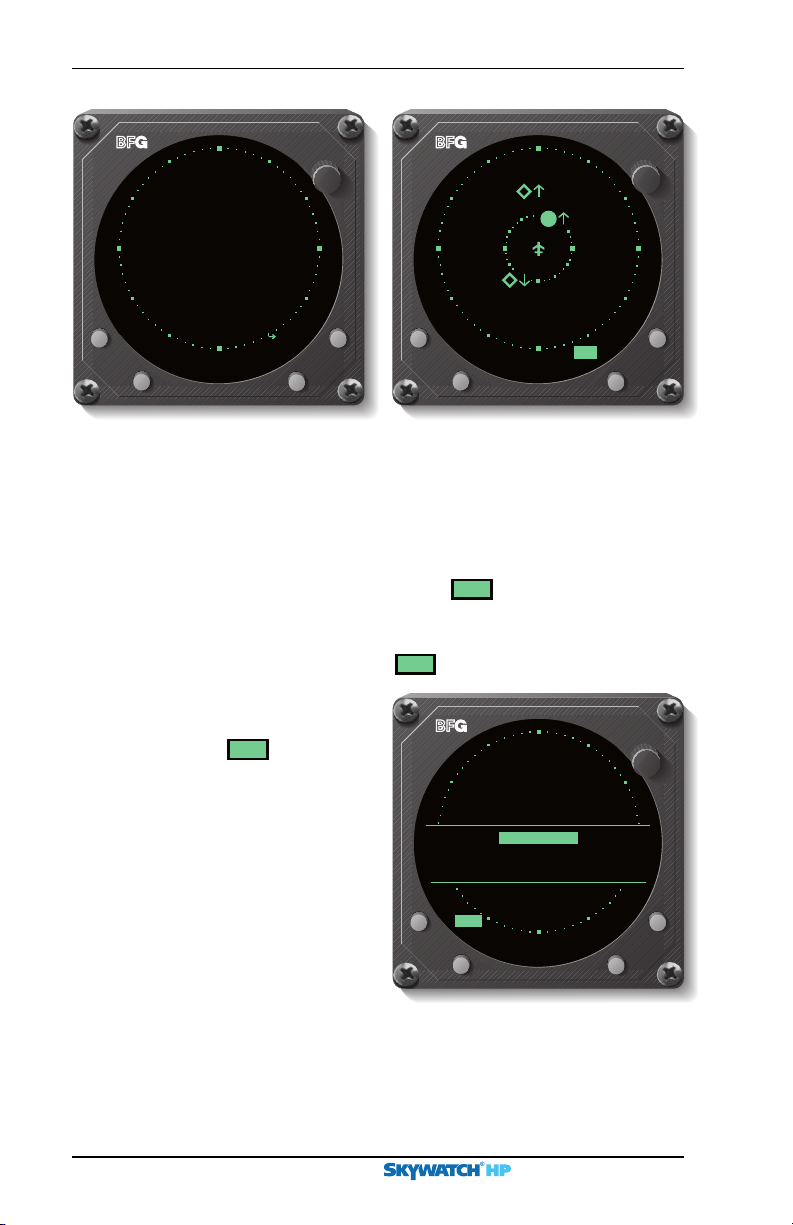
The BFGoodrich screen (figure 3-1) appears and stays on the
display until the power-on self test is complete.
SKY899 passes the test, and your aircraft has a squat
If the
switch, and your aircraft is on the ground,
the standby screen
appears (figure
SKY899 passes
If the
the test, and your
aircraft has a squat
switch, and your aircraft is in the air, the
traffic screen appears
set on the
display range and the
normal vertical display
mode (figure
knob clockwise to the desired display
3-2).
BFGoodrich Avionics Systems,Inc.
6 nmi
3-3).
Figure 3-1. BFGoodrich Screen
OFF
BRT
SKY899 Pilot’s Guide 3-1
Page 26
Turn on the SKY899
Chapter 3 – Operating Instructions
SKY899
OFF
BRT
+10
-02
OFF
BRT
Standby
-26
OPRMSG
TEST
Figure 3-2. Standby Screen
nm
6
NRM
Figure 3-3. In-Flight Traffic Screen
If the SKY899 passes the test and your aircraft does not have a
squat switch, the standby screen (figure
In standby, the
SKY899 waits 5 minutes for critical sensors such
3-2) appears.
as the barometric altimeter to warm up and come on line
before it displays a
Failed screen or
MSG
due to the lack of the
sensor input; however, if you switch into operating mode, the
SKY899 only waits 2 seconds for the sensor inputs before it
displays the Failed screen or
If a
Failed screen similar
to figure
you see
Message Response section
on page
tions with an
3-4 appears, or if
MSG
, refer to the
3-7. For installa-
ARINC 429
barometric altitude input,
turning on the
SKY899
MSG
.
SKY899
Faile d
Barometric Input Error
Error 2 0
during flight causes a
temporary
Preliminary
message while the system
is syncing up to the
Error 20
429
MSG
TEST
data source.
Figure 3-4. Failed Screen
nm
6
BRT
OFF
3-2
SKY899 Pilot’s Guide
Page 27
Chapter 3 – Operating Instructions
Run the Operator-Initiated Self Test
It is recommended, but not required that you should run the
operator-initiated self test before the first flight of the day (or as
specified in your
you get a
1. With the
Failed screen.
button.
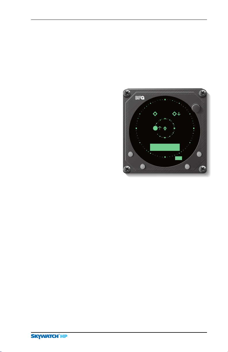
The SKY899 begins its
self test and the test
screen (figure
appears. Upon
successful completion
of the self test, you
will hear “
WATCH
Passed” and the
display will revert to
the previous standby
or traffic screen.
Aircraft Flight Manual [AFM]), and whenever
SKY899
in standby or failed mode, press the
3-5)
SKY-
+10
-02
System Test
NRM
Run the Self Test
-10
SYSTEM
TEST
PROGRE
IN
TEST
BRT
OFF
S
S
nm
6
2. If you hear “
WATCH S
F
ailed” or see a
again. If it fails again, refer to the
on page
3. If you hear “
the test screen, and the
off the
A
vionics Systems dealer for troubleshooting help.
SKY-
ystem Test
3-7
.
SKYWATCH S
SKY899
Figure 3-5. Test Screen
SKY899 F
and contact your authorized
ailed screen, push the
M
essage Response section
ystem Test Passed” without seeing
OFF/BRT
knob is turned to
BFG
TEST
button
BRT
oodrich
, turn
Switch Between Standby & Normal Operating Mode
Preliminary
When you’re on the ground, you must manually switch out of
standby if you want the
SKY899 to display traffic information.
The ability to switch out of standby on the ground in conjunction with the above display mode is especially useful for
scanning the airspace around the airport before takeoff.
1. To manually switch into normal operating mode from the
standby screen (figure
SKY899 Pilot’s Guide
3-2
), press the button labeled
>>
>
>>
OPR
3-3
.
Page 28
15
nm
6
nm
2
nm
6 nmi 2 nmi
15 nmi 6 nmi 2 nmi
Change the Display Range
The SKY899 switches
out of standby into
the above display
mode and
range (figure
If your aircraft has a
squat switch and you
don’t manually switch
out of standby, the
SKY899 automatically
switches out of
standby
8 to 10
seconds after takeoff.
2. To manually switch
into standby from the traffic screen, press the button
labeled
>>
>
>>
The SKY899 goes into standby and the display switches back
to the standby screen. (If your aircraft has a squat switch, the
STB
button label is not displayed while airborne, and the
>
SKY899 will not go into standby while airborne.)
6 nmi
STB
3-6).
.
Chapter 3 – Operating Instructions
BRT
OFF
+10
+04
+94
STB
nm
ABV
6
Figure 3-6.Traffic Screen on the
Ground
If your aircraft has a squat switch, the
standby automatically,
allows the
SKY899 to remain out of standby during a touch-
24 seconds after landing. This delay
SKY899 also goes into
and-go maneuver.
Change the Display Range
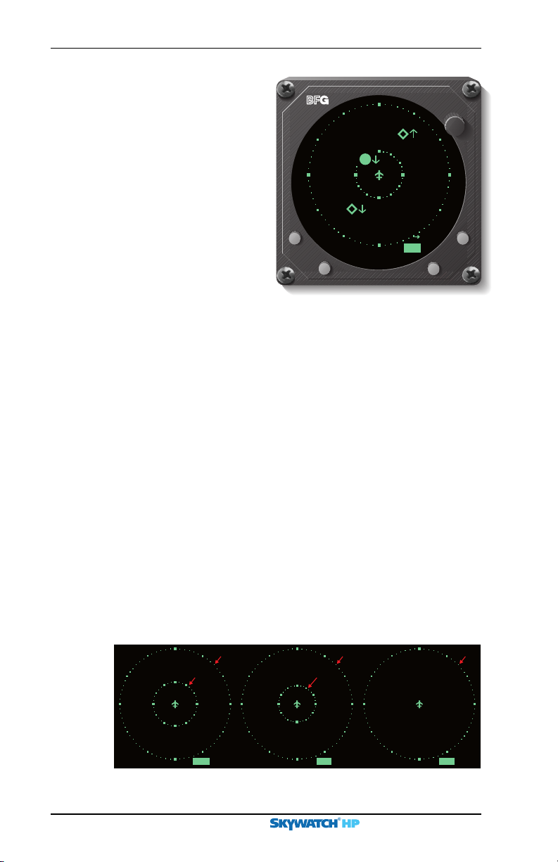
You can change the display range when the SKY899 is in normal
operating mode.
1. Press the display range button to toggle the display range
between
15, 6
, and 2 nmi (figure
3-7
).
Preliminary
Figure 3-7. Display Ranges
3-4
SKY899 Pilot’s Guide
 Loading...