

Page 1
Introduction to WELDSTAR
model WS2003
Spot/Seam control,monitor and machine sequencer
for 50/60Hz and MF resistance welding.
For s/w version 1.69
Document revision 0
Page 2
Manufacturers of
advanced welding
BF Entron Ltd.
Castle Mill Works,
Birmingham new road,
Dudley,
West Midlands,
DY1 4DA
England.
Tel: +44 (0)1384 455401
Fax: +44 (0)1384 455551
BF Entron Ltd.
controls
•Welding controls.
•Thyristors and power supplies
•Power Inverters.
•Meters and Monitors.
•Training and Support.
Email: [email protected]
Web site: www.bfentron.co.uk
•Consultancy.
2
WS2003 V1.69
Page 3
Table of contents
4. WELDSTAR model WS2003
System
5. Introduction and overview
6. Functions
7. …functions
8. …functions
9. Global parameters
10. Program parameters (x64)
11. Multiweld parameters
12. Mounting
13. Connectors
14. Users connections
(discrete)
18. Operation with a fieldbus
19. ...operation with a fieldbus
20. Keypad
21. Menus
22. ..menus
23. Diagnostic screen 1
24. Diagnostic screen 2
25. Status / error codes
29. Configuration menu
30. Edit configuration
33. Edit calibration
36. Edit output map
37. Edit input map
38. Set-up Adapters
39. Backup/Restore
40. Initialise all data
41. System set-up menu
42. Main menu
43. Edit program (AC)
44. Edit program (MF)
46. Edit program (seam)
47. Edit limits
48. Edit Events
49. Electrode menu
50. Stepper status
51. Edit stepper
52. Stepper presets
53. Edit counter
54. ..edit counter(tip-dressing)
55. Sequencer
56. Sequencer Menu
57. Edit sequence
59. Example sequence
60. Weld log
61. View log screen 1
62. View log screen 2
63. Copy program
64. Copy Electrode
65. I/O status
66. Fieldbus input status
67. Analog status
68. Program selection
69. OHMA (Air over oil) system
71. Disabling edits
72. Pop-up current meter
73. Replacing a WS2000 timer
74. Operation: basic spot weld – no
weld faults.
75. Operation: basic spot weld – weld
fault
76. Operation: repeat spot weld
77. Operation: pulsation spot weld
78. Operation: upslope and
downslope
79. Operation: roll-spot welding
80. Operation: seam welding (dual
heat)
81. Operation: seam welding (preheat)
82. Operation: EOS signal
83. Operation: Retract
84. Operation: Hi-lift
-----------------------------------------------------------
85. Multiwelding
86. Configuring for multiwelding
87. Electrode/Transformer assignment
88. Assigning a weld program to an
electrode
89. Multi-gun operation
90. Multi-gun cascade operation
92. Program selection (multiweld)
-----------------------------------------------------------
93. WS98-2003 PC software
3
WS2003 V1.69
Page 4
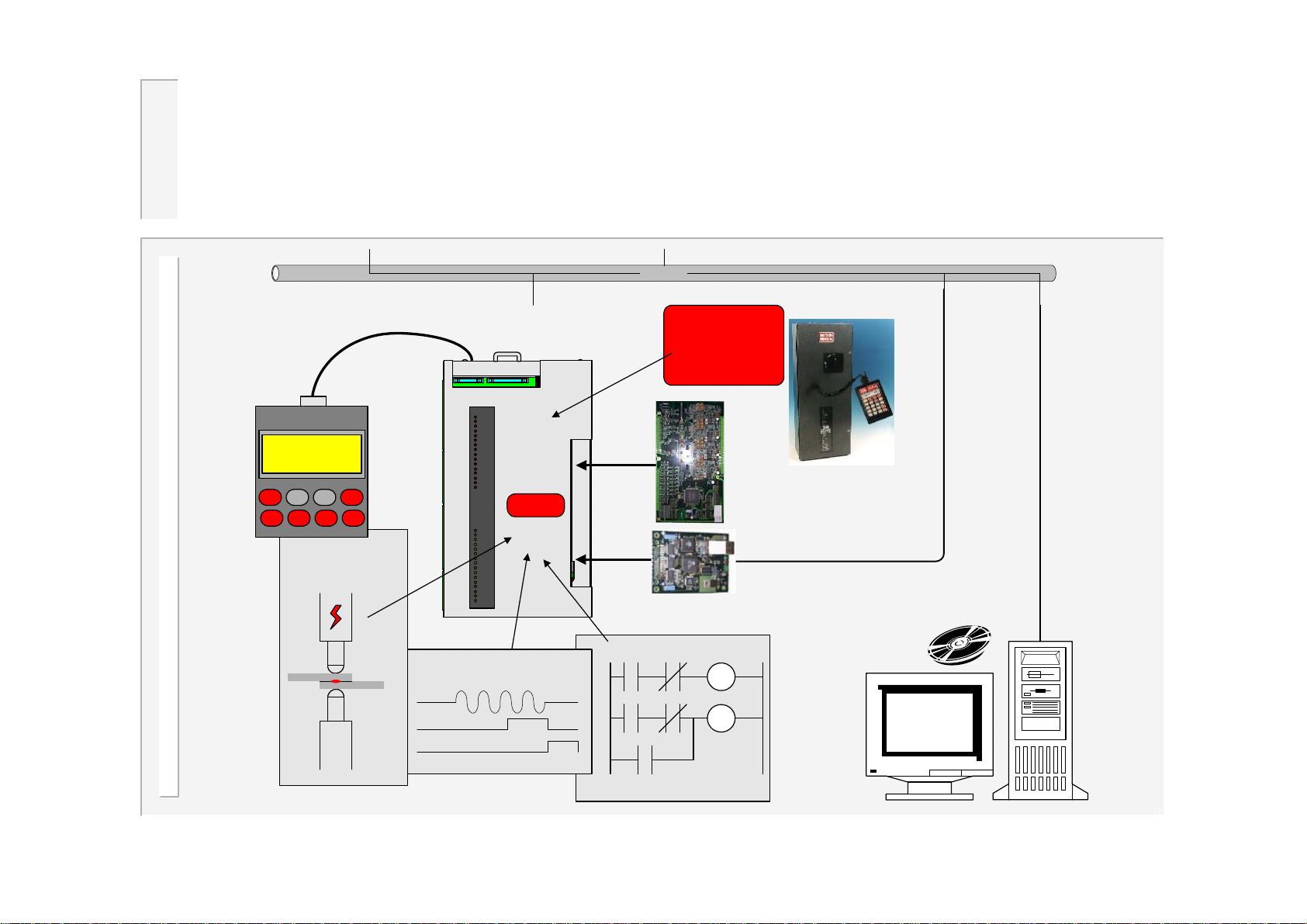
WELDSTAR model WS2003 System
Ethernet
WSP3
PROGRAMMING
PENDANT
WELDING
CONTROL
WS2003 TIMER
WS2003
EVENT TIMER
WELDSTAR
2000
compatible !
*Optional Plug-in adapter
cards for special functions.
*Optional Ethernet adapter
required for connection to
Ethernet
LOGIC SEQUENCER
WS98-2003
Software for PC
4
WS2003 V1.69
Page 5
Introduction and overview
This manual details the features of the WS2003 timer, and shows how
This manual details the features of the WS2003 timer, and shows how
to program the timer using the WSP3 programmer.
to program the timer using the WSP3 programmer.
The new WELDSTAR model WS2003 is a direct plug-in replacement for the original WS2000. It
will fit into existing cabinets, and will work with the existing power supply. Existing connections
are duplicated, including outputs at 110V AC or 24VDC
A new programming pendant , type WSP3 is available, and provides a
larger multi-line display, making programming easy.
A powerful built-in logic sequencer program provides the timer with a
flexible means of fully controlling small machines or tooling
arrangements, without the need for additional hardware.
A plug-in option board provides a 10/100Base-T Ethernet connection.
Units may then be networked to a PC running WS98-2003 software
for programming and monitoring purposes.
Fieldbus operation (Profibus, Interbus, DeviceNet Modbus etc.) is
supported via plug-in option boards.
. MF operation is also supported.
5
BF
ENTRON
F
WSP3
WS2003 V1.69
Page 6
Functions
• Compatible with original Weldstar 2000
• AC 50/60Hz and MFDC (medium frequency) welding all supported.
• Spot / Repeat /Roll-spot / Seam (dual heat) / Seam (pre-heat) welding.
• Single, dual or OHMA (Air over Oil) gun operation.
• Multiwelding with up to 16 SCR/transformers
• Retract/high-lift control.
• Dual weld intervals plus pulsation, upslope and downslope.
• Constant current regulation.
• Up to 64 programmes with internal or external selection.
• Current monitoring with high, low and pre limits. Programmable blocking and weld
retry functions.
• Proportional valve controller (0..10V or 4..20mA).
• Programmable outputs (events).
• Machine sequencer logic
• Welding programmes may be linked together to form complex spot schedules.
6
WS2003 V1.69
Page 7
…functions
• Contactor timer.
• Head-lock function.
• Analog output of current waveform.
• Electrode management including stepping, counting and tip-dressing
functions, with programmable blocking and preset curves.
• Outputs will drive 24V DC or 110V AC loads.
• Primary or Secondary feedback via Toroid.
• Toroid and PV calibration functions.
• Toroid test function.
• Disable edit function.
• External plug-in programming pendant with large backlit 4x20 lcd display,
and data backup facility.
• RS232 port, for PC communications.
• Expandable via plug-in option cards
• (Ethernet, Profibus, DeviceNet, Interbus, Modbus TCP/IP, Ethernet/IP
etc).
7
WS2003 V1.69
Page 8
…functions
In early 2008, a number of new circuits were added to the original design.
These are used to provide the following additional features:
• 0..10v or 4..20mA input for pressure monitoring.
• Two general purpose 0..10V inputs can be used by the sequencer. One of
these inputs may be used to connect a CT for current measurement.
Note that these features are not available when running this firmware on the
original design.
8
WS2003 V1.69
Page 9
Global parameters
Configuration
•Sequence (Spot / Roll-spot / Seam(2-heat) / Seam(pre-heat)
•Single gun / Dual gun / OHMA gun / Multi-gun / Multi-gun cascade.
•Discrete/Fieldbus I/O
•Retract (x2): (Simple / Hi-lift+ / Hi-lift- / Maintained / OHMA)
•Program select (Binary / 1-of-4 )
•SCR select (Binary / 1-of-4)
•Frequency (AC 50 Hz / AC 60 Hz / MF 50Hz / MF 60Hz)
•Contactor time (0..200 s)
•Blanking (On/Off)
•Toroid test (On/Off)
•Sensor (Toroid / CT)
•Heat range (Wide/High/Low)
•EOS mode (Cancel/fixed)
•If fault (Head-lock/Stop/Continue/EOS/No EOS)
•Sequencer (On/Off)
•Toroid attenuation factor (1..4)
•Count/Log sync (On/Off)
•Pressure units (kN/lb)
•Analog output (PV/Current).
Calibration (x2)
•Sensor sensitivity(100..60000 mV/kA)
•S/P ratio (1:1..199:1)
•S/P offset (-10kA..+10kA)
•Pressure (2 points, kN/V)
•Inverter (2 points, kA/%heat)
•Analog output scale (0..60kA).
•Analog input gain (0.9..2.5)
•Analog input offset(-9.99…+9.99)
Counter (x2)
• Actual count (0..9999).
• Terminal count(0..9999).
• Stop/continue at end.
• Tip dressing (on/off)
• Dressings (0..9999)
• Dress when new (on/off)
Stepper (x2)
• Stepper on/off.
• Stop /continue at end
• Curve(10 point, interpolated)
Sequencer
•Up to 250 statements
Output Map
• Normal/Event/Sequencer/Fieldbus (x12)
Input Map
• Normal/Sequencer (x14)
9
WS2003 V1.69
Page 10
Program parameters (x64)
Weld program
•Pre-squeeze (0..99 cycles)
•Squeeze (0..99 cycles)
•Weld1 (0..99 cycles)
•Cool1(0..99 cycles)
•Weld2(0..99 cycles)
•Cool2(0..99 cycles)
•Pulses(0..99)
•Hold(0..99 cycles)
•Off(0..99 cycles)
•Pressure (0..100%)
•Heat 1(0..99.9%)
•Heat 2(0..99.9%)
•Current 1 (0..60kA)
•Current 2 (0..60kA)
•Balance (seam only)
•Normal/Link program
•Upslope(0..99 cycles)
•Downslope(0..99 cycles)
Additional parameters for OHMA gun
•OHMA gun open (0..99 cycles)
•OHMA gun close (0..99 cycles)
•OHMA retract open (0..99 cycles)
•OHMA retract delay (0..99 cycles)
•OHMA retract close (0..99 cycles)
Monitor limits
•Current monitor (On/Off)
•Current low limit,weld1 (0..99%)
•Current high limit,weld1 (0..99%)
•Current pre-limit,weld1 (0..99%)
•Current low limit,weld2 (0..99%)
•Current high limit,weld2 (0..99%)
•Current pre-limit,weld2 (0..99%)
•Pre-limit count (0..99)
•Retry (On/Off)
•Pressure monitor (On/Off)
•Wait for pressure (On/Off)
•Pressure high limit (0..100%)
•Pressure low limit (0..100%)
Events
•4 x 4 trigger points
10
WS2003 V1.69
Page 11
Multiweld parameters
When either multi-gun or multi-gun cascade modes are selected, the following additional
parameters are available:
Transformers
•Electrode number (1..16) for each transformer (x16).
Calibration (extended to x16)
•See ‘Global parameters’ for parameter list.
Counter (extended to x16)
•See ‘Global parameters’ for parameter list.
Stepper (extended to x16)
•See ‘Global parameters’ for parameter list.
Weld program (x64)
•Electrode number(1..16).
11
WS2003 V1.69
Page 12
Mounting
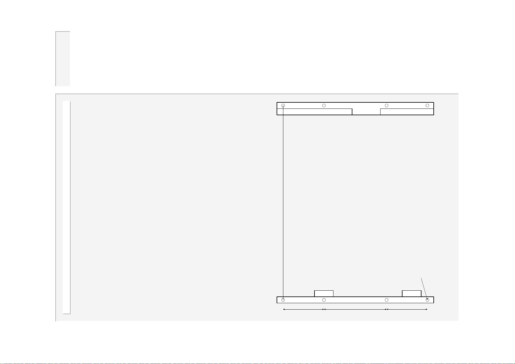
If you have purchased a complete
system including the WS2003 timer, then
the timer will already be mounted in the
case.
If you have purchased a timer only kit,
then you will need to mount the timer to
the rest of your equipment.
The timer is supplied complete with two
metal mounting brackets. These
brackets need to be fixed to a flat
surface, as shown in the diagram.
It is recommended that the four holes for
the top bracket are made into vertical
slots. The position of the bracket may
then be adjusted to give the best fit to
the timer.
Top bracket
375
4.5 dia.
Bottom
bracket
66.5 66.597.0
12
WS2003 V1.69
Page 13
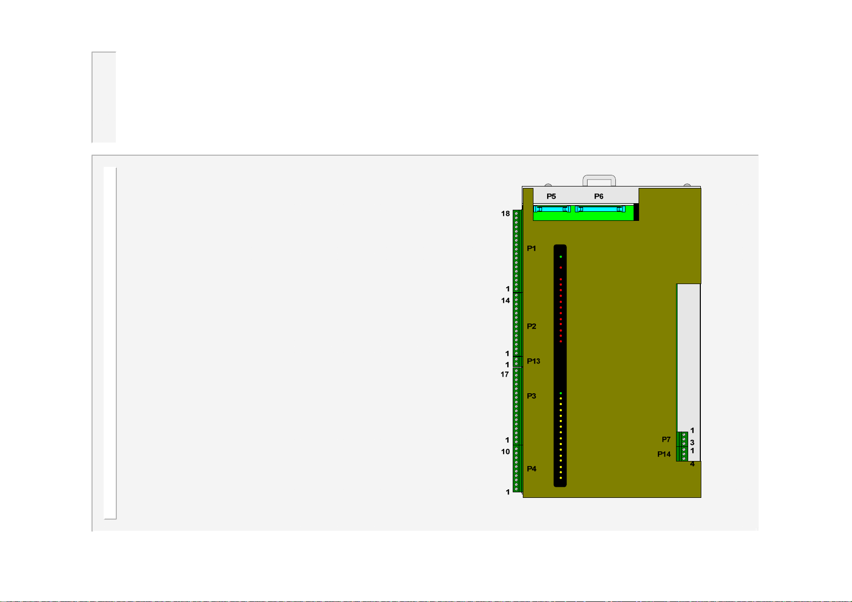
Connectors
Connectors P1,P2,P3,P4,P7,P13 and P14
are two-part terminals, for use with wires
up to 1mm
Connectors P5 and P6 are used internally
via ribbon cable assemblies, and are not
used for users connections.
Connector P7 is the preferred connection
for the current measurement toroid. If the
WS2003 timer is being retrofitted into an
older system, there may already be a toroid
connected and routed internally via ribbon
2
.
P6. In this case, no connection should be
made to P7. However, if possible, an
existing toroid should be re-routed to P7.
P13 and P14 are not present on units
produced before early 2008.
13
WS2003 V1.69
Page 14
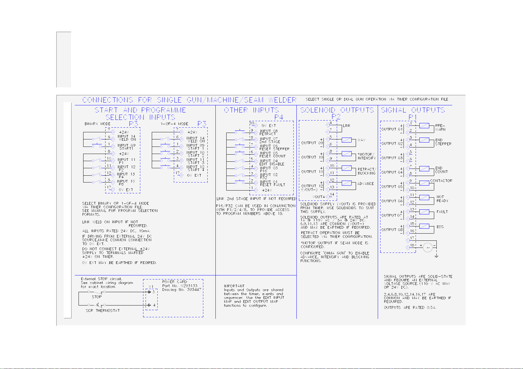
Users connections (discrete)
14
WS2003 V1.69
Page 15
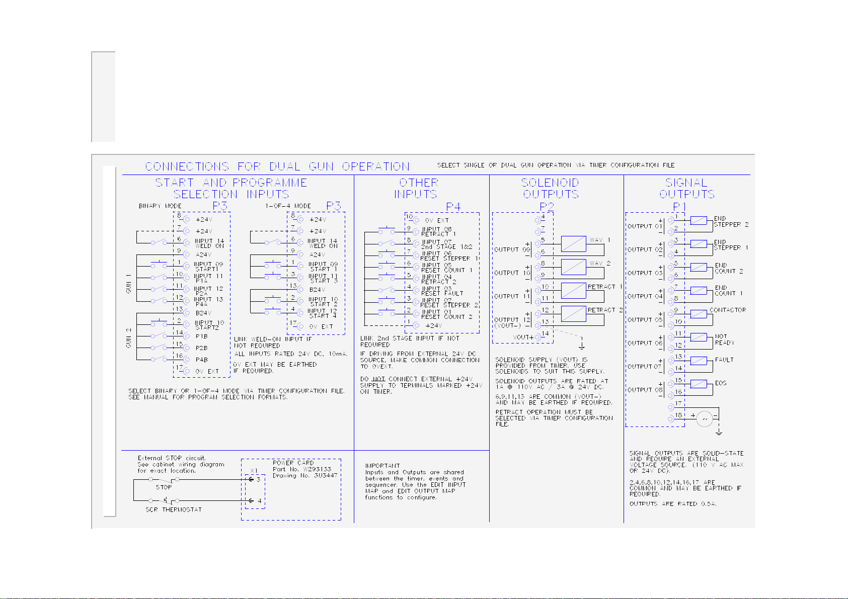
…users connections
15
WS2003 V1.69
Page 16
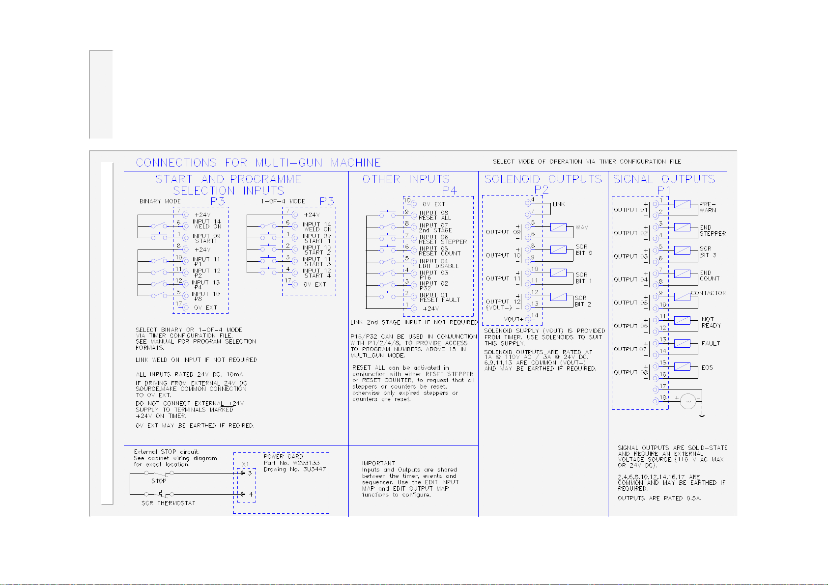
…users connections
16
WS2003 V1.69
Page 17
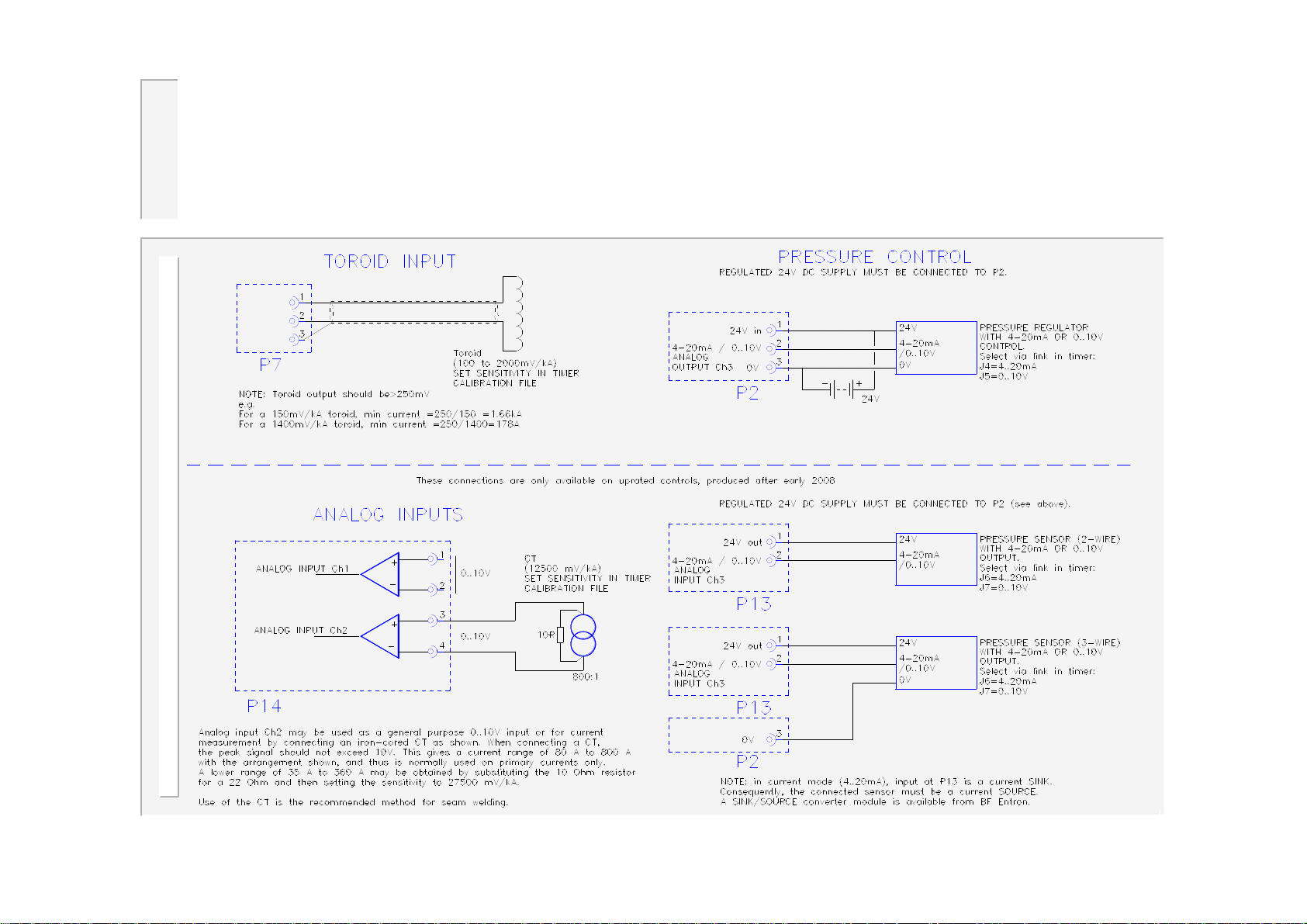
…users connections
17
WS2003 V1.69
Page 18
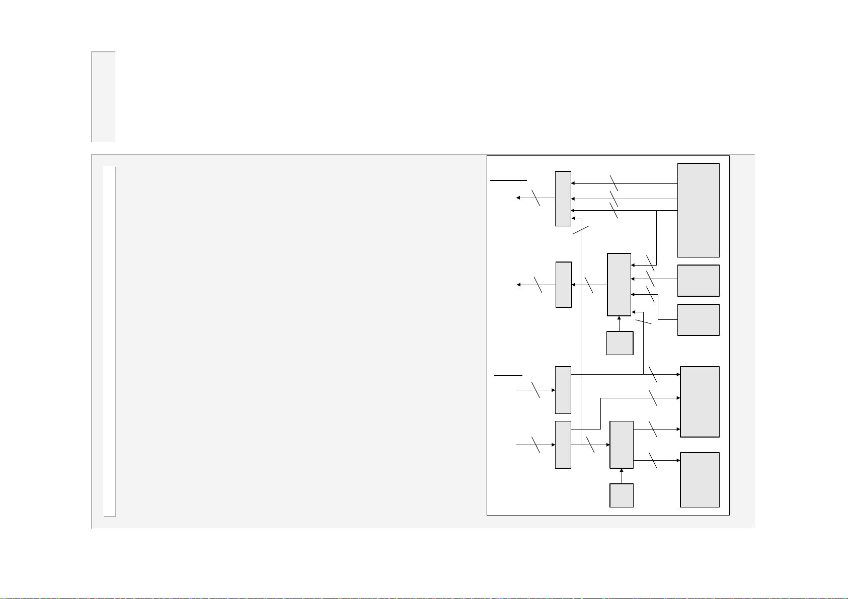
Operation with a fieldbus
WS2003 can be operated on a fieldbus,
instead of through the discrete I/O
connections.
An optional adapter card is required to
interface to the required fieldbus. Adapter
cards are available for all popular fieldbus
types: (Profibus-DP, Interbus-S, DeviceNet,
Ethernet TCP/IP/MODBUS, etc.)
The diagram opposite shows, schematically,
how the I/O is arranged. Selection between
Discrete or Fieldbus operation is via the timer
configuration.
The tables on the next page show the fieldbus
OUTPUTS
Fieldbus
outputs
Physical
outputs
INPUTS
Fieldbus
inputs
Physical
inputs
8
3
2
2
1
1
2
3
2
1
6
1
2
F24V, SCR STAT
1
4
8
1
2
Mux
Output
Map
Mux
1
6
1
6
1
6
8
3
1
1
Pressure
Error code
Timer
Output
Events
Sequencer
2
2
4
4
Timer
bit assignments for both single gun/multi-gun
and dual-gun operation.
WS2003 I/O routing
18
Input
Map
Sequencer
WS2003 V1.69
Page 19
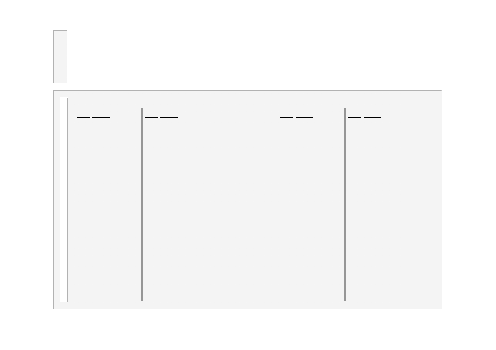
...operation with a fieldbus
Single gun /Multi-gun
INPUT from bus to timer OUTPUT from timer to bus
Bit No.
Function Bit No. Function
0 START 1 0 Prewarning
1 START 2 1 End of stepper
2 START 3 2 Reserved
3 START 4 3 End of count
4 2nd Stage 4 Contactor
5 Weld on* 5 Not ready
6 Reserved 6 Fault
7 Reserved 7 End of sequence (EOS)
8 Reset counter 8 Weld air valve 1 (WAV 1)
9 Reset stepper 9 Low force air valve (LFAV) / Motor
10 Ret r act 1 / Reset All 10 Retract air valve 1 (HAV 1)
11 Reserved 11 Reserved
12 Reserved 12 Discret e input I10
13 Reserved 13 Discret e input I11
14 Reserved 14 Discret e input I12
15 Reset fault 15 Discret e input I13
16 Program bit 1 16 Error c ode bit 1
17 Program bit 2 17 Error c ode bit 2
18 Program bit 4 18 Error c ode bit 4
19 Program bit 8 19 Error c ode bit 8
20 Program bit 16 20 Error c ode bit 16
21 Program bit 32 21 Error c ode bit 32
22 Reserved 22 Error code bit 64
23 Reserved 23 Error code bit 128
24 Discrete output Q01 24 Pressure bit 1 Discrete input I1
25 Discrete output Q02 25 Pressure bit 2 Discrete input I2
26 Discrete output Q03 26 Pressure bit 4 Discrete input I3
27 Discrete output Q04 27 Pressure bit 8 Discrete input I4
28 Discrete output Q05 28 Pressure bit 16 Discrete input I5
29 Discrete output Q06 29 Pressure bit 32 Discrete input I6
30 Discrete output Q07 30 Pressure bit 64 Discrete input I7
31 Discrete output Q08 31 Pressure bit 128 Discrete input I8
*The discrete Weld on input must also be on to enable welding.
Map=1 Map=2
Dual gun
INPUT from bus to timer OUTPUT from timer to bus
Bit No.
Function Bit No. Function
0 START 1 0 End of stepper 2
1 START 2 1 End of stepper 1
2 START 3 2 End of count 2
3 START 4 3 End of count 1
4 2nd Stage 4 Contactor
5 Weld on* 5 Not ready
6 Reserved 6 Fault
7 Reserved 7 End of sequence (EOS)
8 Reset counter 1 8 Weld air valve 1 ( WAV 1)
9 Reset stepper 1 9 Weld air valve 2 ( WAV 2)
10 Ret r act 1 10 Retract air valve 1 (HAV 1)
11 Reset counter 2 11 Retract air val ve 2 (HAV 2)
12 Reset stepper 2 12 Discrete input I10
13 Ret r act 2 13 Discrete input I11
14 Reserved 14 Discret e input I12
15 Reset fault 15 Discret e input I13
16 Program bit 1 16 Error c ode bit 1
17 Program bit 2 17 Error c ode bit 2
18 Program bit 4 18 Error c ode bit 4
19 Program bit 8 19 Error c ode bit 8
20 Program bit 16 20 Error c ode bit 16
21 Program bit 32 21 Error c ode bit 32
22 Reserved 22 Error code bit 64
23 Reserved 23 Error code bit 128
24 Discrete output Q01 24 Pressure bit 1 Discrete input I1
25 Discrete output Q02 25 Pressure bit 2 Discrete input I2
26 Discrete output Q03 26 Pressure bit 4 Discrete input I3
27 Discrete output Q04 27 Pressure bit 8 Discrete input I4
28 Discrete output Q05 28 Pressure bit 16 Discrete input I5
29 Discrete output Q06 29 Pressure bit 32 Discrete input I6
30 Discrete output Q07 30 Pressure bit 64 Discrete input I7
31 Discrete output Q08 31 Pressure bit 128 Discrete input I8
Map=1 Map=2
19
WS2003 V1.69
Page 20
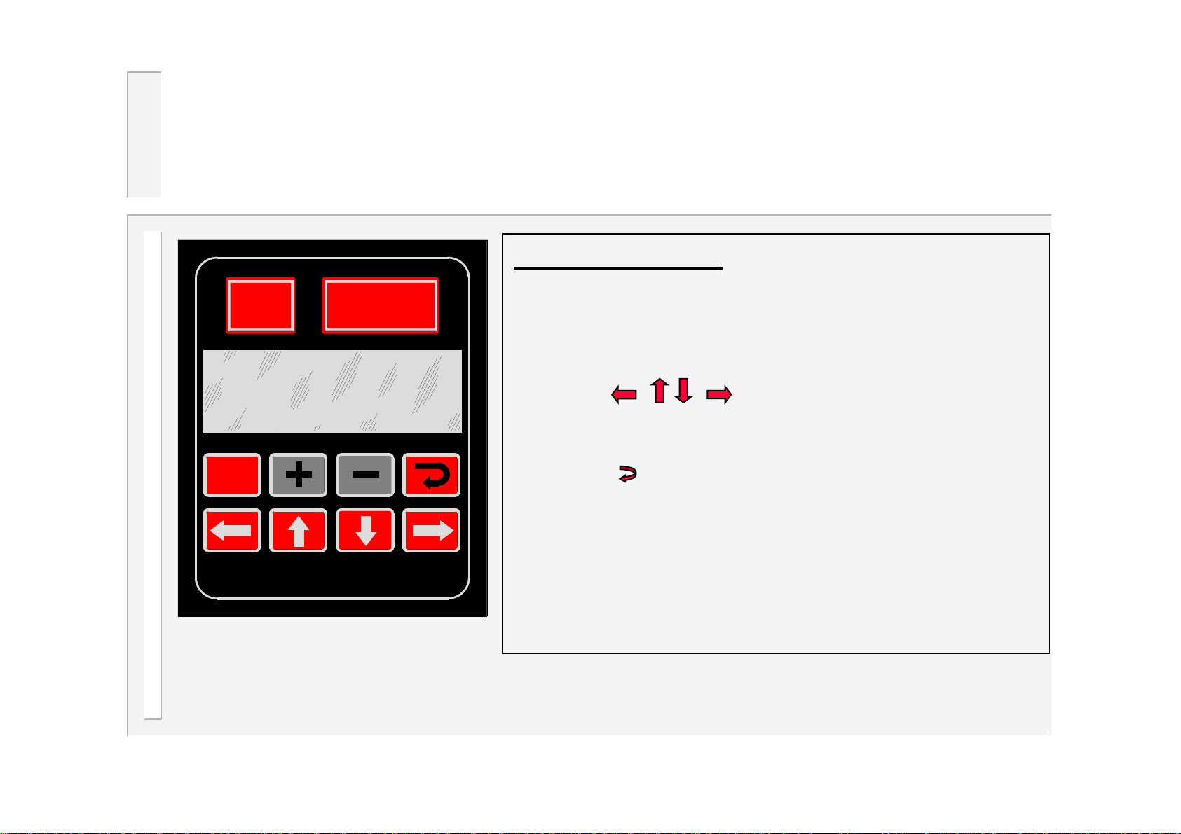
Keypad
BF
ENTRON
WSP3
Using the keypad
•Press the F (function) key to return to the previous
screen, or to move between menu screens (see
menus).
•The selected function or parameter will flash.
•Use the keys to select a different
function or parameter. The visible window will scroll
when required.
F
•Press the key to access the selected function.
•Press the + or - keys to alter the selected
parameter. Press + and – together to set a
parameter to 0 or its minimum value.
•On some screens, certain keys can have a special
function. These are noted on the page describing
that screen.
20
WS2003 V1.69
Page 21
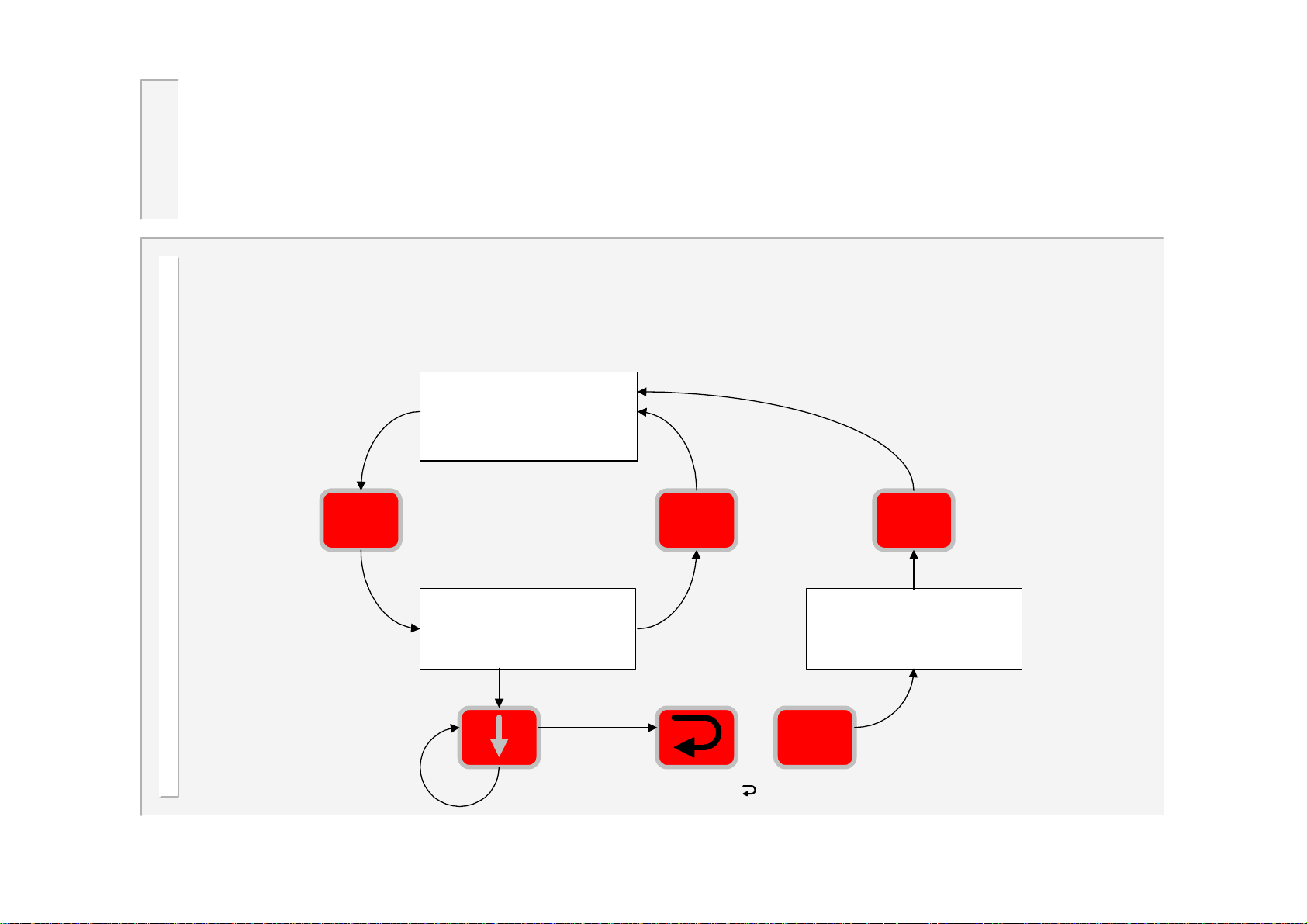
Menus
The various functions of the timer are arranged into a set of menus and
screens. The diagrams below shows how these are organized and accessed:
Diagnostic screen
LOW CURRENT WELD 2
PROG=0 COUNT1= 10
I1=10.5kA
I2=12.1kA
F F F
STP1= 27%
P->5.00kN
Select bottom line
in main menu
(Version number)
<<< MAIN MENU >>>
USE PROGRAM -EXT( 0)
EDIT PROGRAM FILE
EDIT LIMITS FILE
<<< CONFIG. MENU>>>
EDIT CONFIGURATION
EDIT CALIBRATION
EDIT OUTPUT MAP
F+
Press and hold , then type
21
F
WS2003 V1.69
Page 22
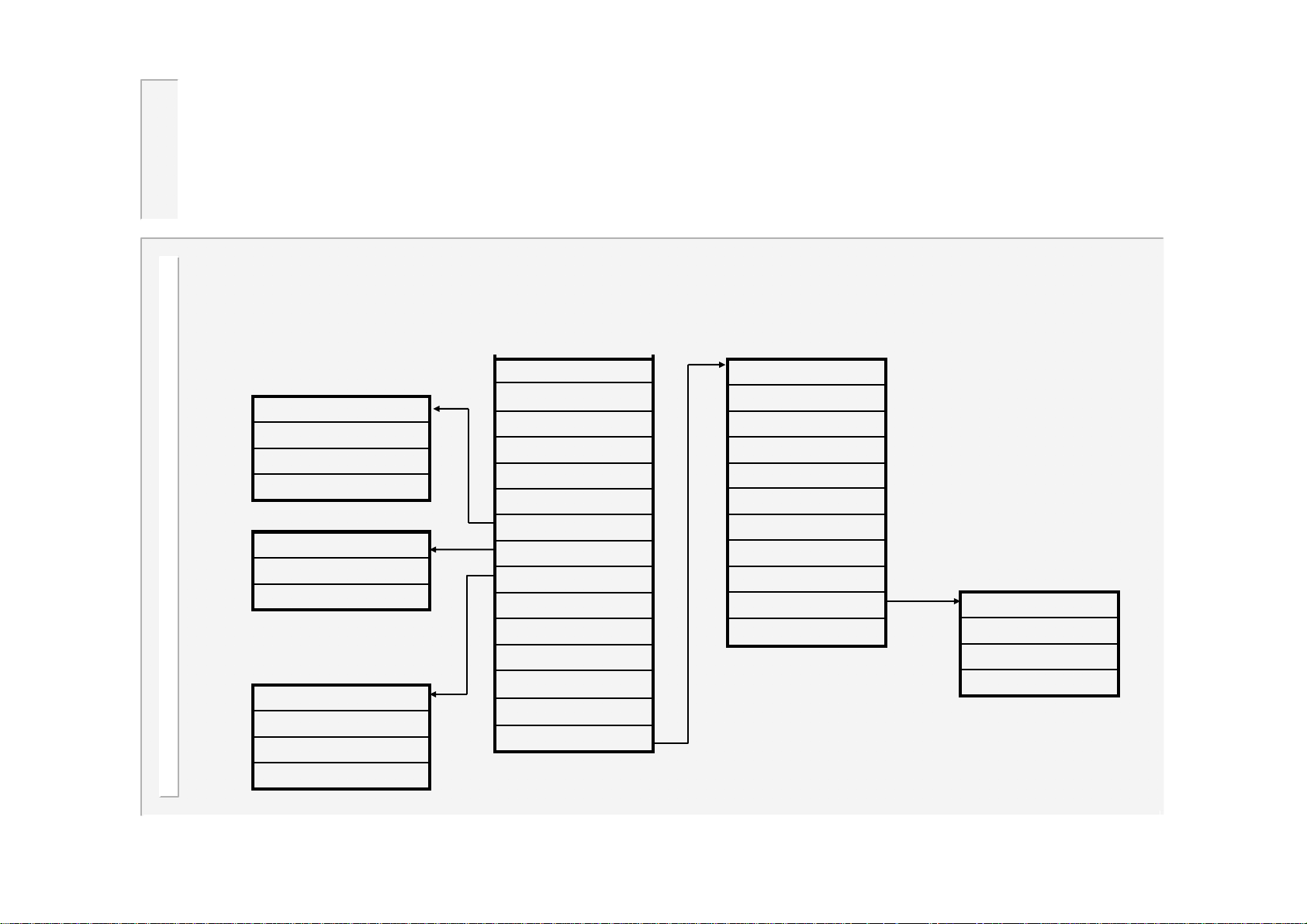
..menus
<< ELECTRODE MENU >>
Stepper status
Edit stepper
Edit counter file
<< WELD LOG >>
View log
Clear log
<<SEQUENCER MENU>>
Edit sequence
Erase sequence
Status: Idle
<< MAIN MENU >>
Use program
Edit program file
Edit limits file
Edit events file
Edit cascade**
Electrode menu
Weld log
Sequencer menu
Copy program
Copy Electrode
I/O Status
Fieldbus inputs
Analog Inputs
WS2003 version
<< CONFIG. MENU >>
Edit configuration
Edit calibration
Edit output map
Edit input map
Edit transformers*
Setup adapters
Backup all data
Restore all data
Initialise all data
Edit system setup
**Only if multi-gun cascade mode is configured.
*Only if multi-gun or
multi-gun cascade
mode is configured.
<< SYSTEM SETUP >>
Show system files
Select active file
Restart system
22
WS2003 V1.69
Page 23
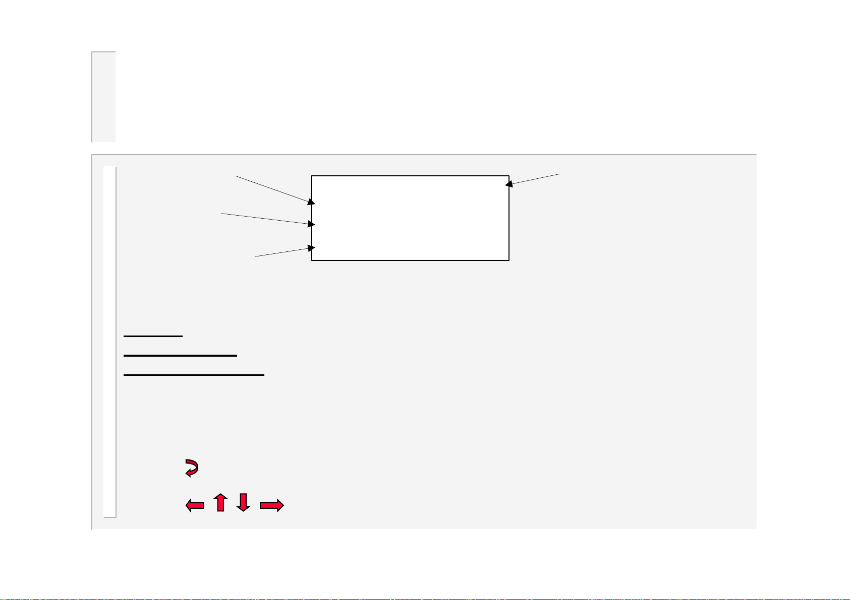
Diagnostic screen 1
LOW CURRENT WELD 2
Measured current
for weld1
PROG=0
I1=10.5kA
StatusProgram used
Measured current
for weld2
Note that some elements may not be visible, if that feature is not being used.
Status:
Program used:
Measured current:
•Press to reset faults (same action as external input). The counters will also be reset if they
have reached the end of count.
•Press to change to diagnostic screen 2.
diagnostic error messages. If more than one exists, these are flashed sequentially.
this is the program number that was last used.
the RMS current measured during the last weld.
I2=12.1kA
23
WS2003 V1.69
Page 24
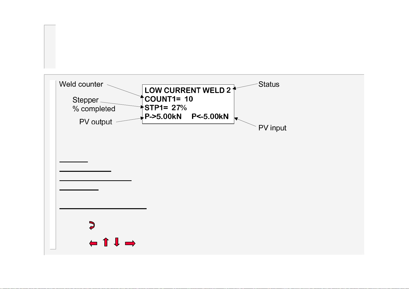
Diagnostic screen 2
Note that some elements may not be visible, if that feature is not being used.
Status:
Weld counter:
Stepper %complete
PV output:
the selected program.
Measured PV feedback:
•Press to reset faults (same action as external input). The counters will also be reset if they
have reached the end of count.
•Press to change to diagnostic screen 2.
diagnostic error messages. If more than one exists, these are flashed sequentially.
the present value in the counter (updates after each weld)
:shows the progress along the stepping curve.
The output from the PV controller is determined by the pressure parameter in
the dynamic value measured from the feedback channel.
24
WS2003 V1.69
Page 25
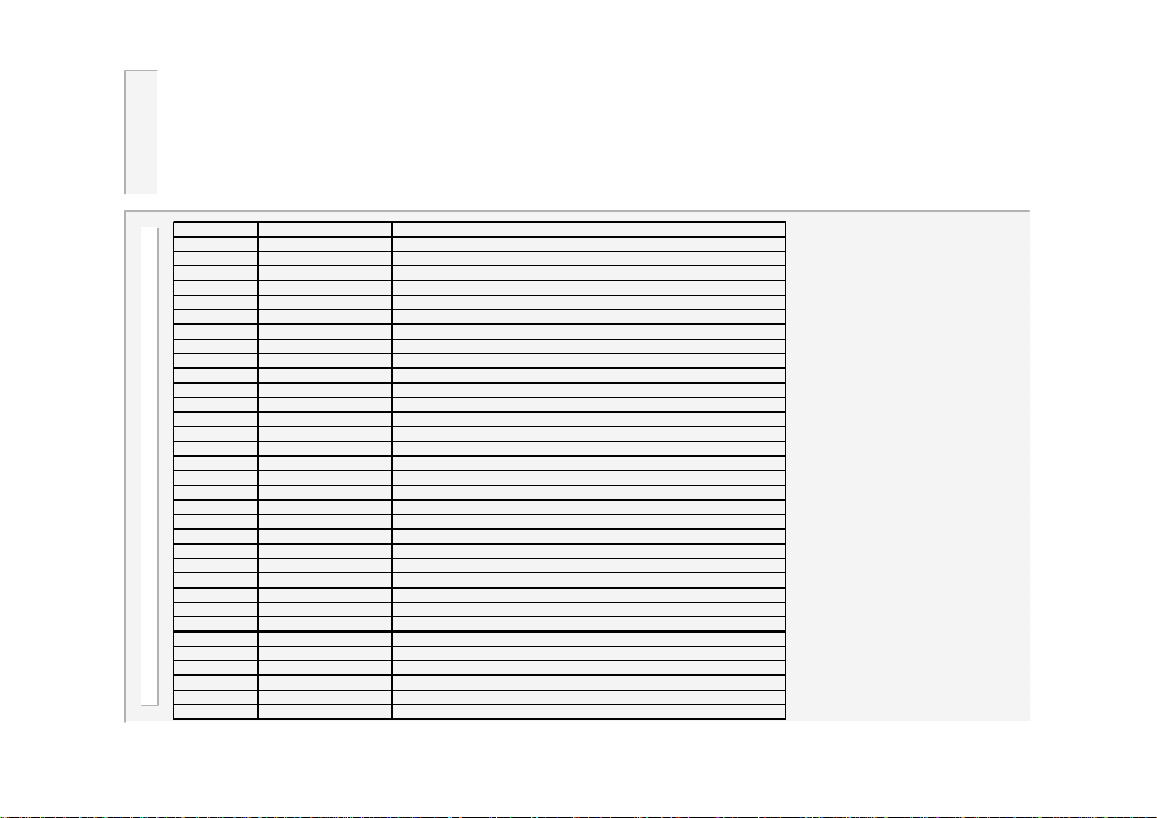
Error codes are sent to
A
Status / error codes
the fieldbus (if fitted).
The description (abbreviated) appears on the top line of the diagnostic screen.
Error code Description
0 No errors
1 Configuration error Edit the configuration file
2 No synchronising signal Check 27V AC sync. signal source / Check frequency in configuration file
3
4
5
6 Retract not ready Operate retract input
7 Data error Edit program
8 Weld off Close Weld-on switch
9 No current (weld 1) Check secondary circuit / check toroid connection
10 No current (weld 2) Check secondary circuit / check toroid connection
11 Low current (weld 1) Check secondary circuit or adjust parameters
12 Low current (weld 2) Check secondary circuit or adjust parameters
13 Pre-alarm (weld 1) Check secondary circuit or adjust parameters
14 Pre-alarm (weld 2) Check secondary circuit or adjust parameters
15 High current (weld 1) Check secondary circuit or adjust parameters
16 High current (weld 2) Check secondary circuit or adjust parameters
17 Config. Changed Restart the timer (power off/on)
18 No 2nd stage Check the 2nd stage input
19 Toroid overrange Reduce current, or use an external signal attenuator
20 Toroid open circuit Inspect toroid connection
21 Toroid short circuit Inspect toroid connection
22
23
24
25 Sequencer error Edit sequencer program
26 STOP or SCR hot Check external STOP circuit or scr cooling.
27 No 24V supply Check fuse in timer
28
29
30 Headlocked Operate reset fault input
31 No adapter Fit adapter or change configuration
32 Fieldbus inactive Check fieldbus connections / check bus master
dvice
25
WS2003 V1.69
Page 26
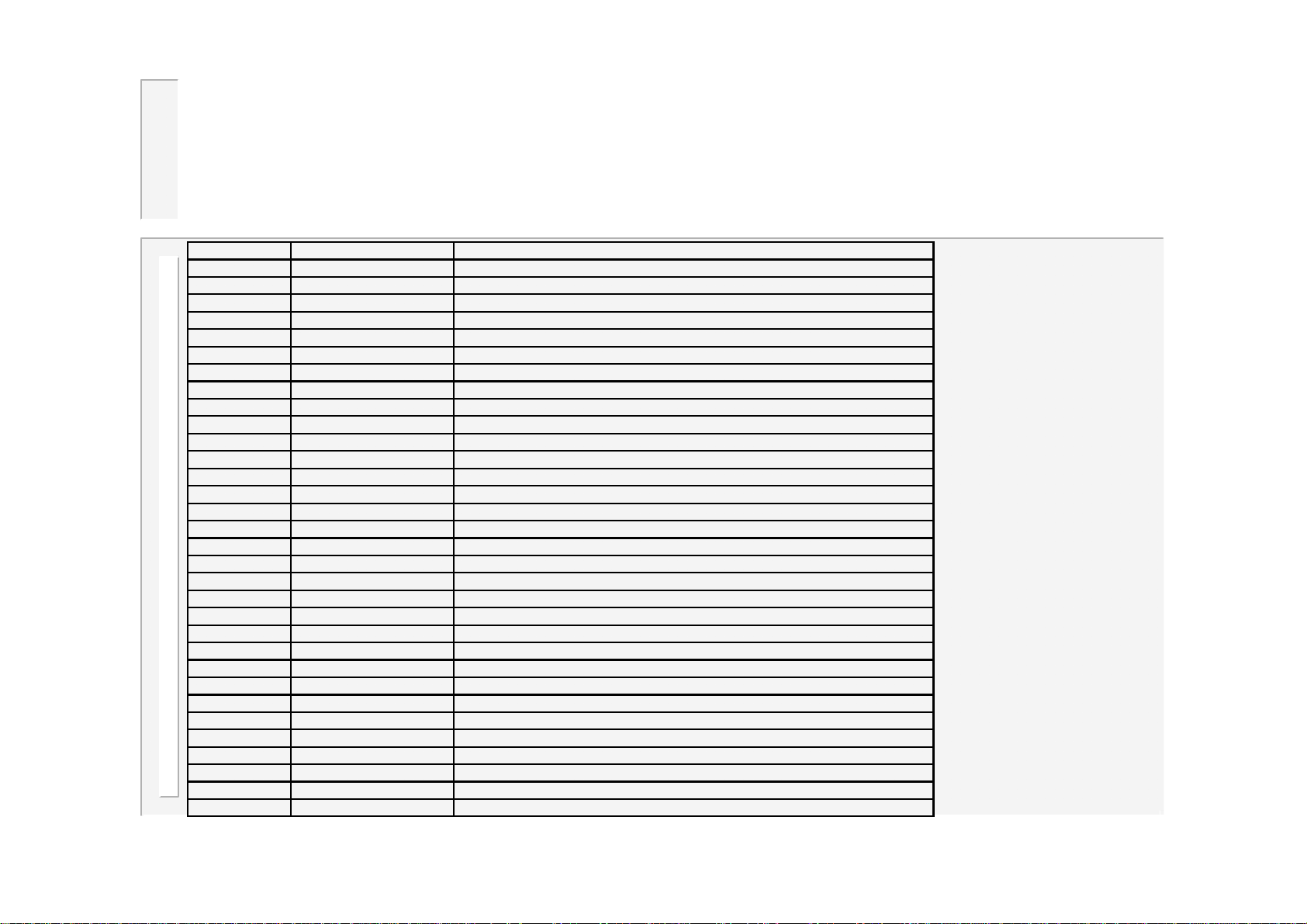
..status / error codes
A
Error code Descrip tion
33
34
35
36
37
38
39
40
41
42 Transformer hot Check water flow to welding transf ormer / Reduce duty
43
44
45 Inverter hot Check water flow to inverter / Check inverter fans/ Reduce duty
46 Inverter voltage error Check mains supply to inverter
47
48
49
50 Short circuit Check cables from invert er to welding transformer/ Check transform er
51 Inverter no current Check cables from inverter to weldi ng transformer/ Check transformer
52 Earth fault Check cables from i nverter to welding transformer/ Check transformer
53 Inverter disabled Check control connecti ons to invert er
54 Max. pulse width Check secondary circuit / Reduce heat/current
55 Max. prim ary current Check secondary circuit / Reduce heat /current
56
57 No Current(Weld off) Cl ose Weld-on switch
58 Low pre ssu re Check air pressure syst e m
59 High pressure Check air pressure system
60 Pressure not ready Check air pressure system
61 Switch off start The START signal is still on after a STOP or power-up condition.
62
63
64
dvice
26
WS2003 V1.69
Page 27
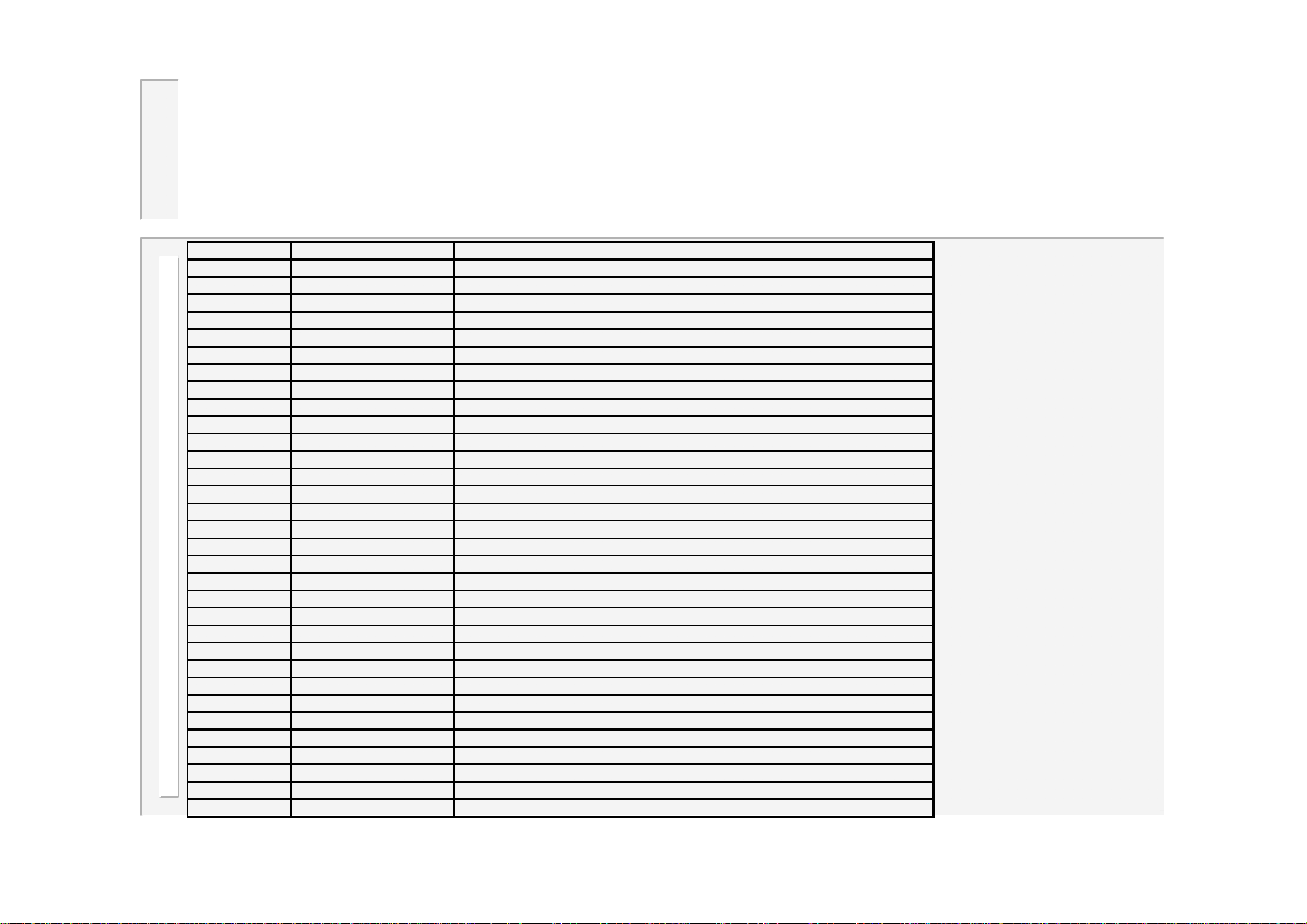
..status / error codes
A
Error code Descrip tion
65 Stepper 1 end Reset stepper 1
66 Stepper 2 end Reset stepper 2
67 Stepper 3 end Reset stepper 3
68 Stepper 4 end Reset stepper 4
69 Stepper 5 end Reset stepper 5
70 Stepper 6 end Reset stepper 6
71 Stepper 7 end Reset stepper 7
72 Stepper 8 end Reset stepper 8
73 Stepper 9 end Reset stepper 9
74 Stepper 10 end Reset stepper 10
75 Stepper 11 end Reset stepper 11
76 Stepper 12 end Reset stepper 12
77 Stepper 13 end Reset stepper 13
78 Stepper 14 end Reset stepper 14
79 Stepper 15 end Reset stepper 15
80 Stepper 16 end Reset stepper 16
81 Stepper 1 prewarn
82 Stepper 2 prewarn
83 Stepper 3 prewarn
84 Stepper 4 prewarn
85 Stepper 5 prewarn
86 Stepper 6 prewarn
87 Stepper 7 prewarn
88 Stepper 8 prewarn
89 Stepper 9 prewarn
90 Stepper 10 prewarn
91 Stepper 11 prewarn
92 Stepper 1 prewarn
93 Stepper 13 prewarn
94 Stepper 14 prewarn
95 Stepper 15 prewarn
96 Stepper 16 prewarn
dvice
27
WS2003 V1.69
Page 28
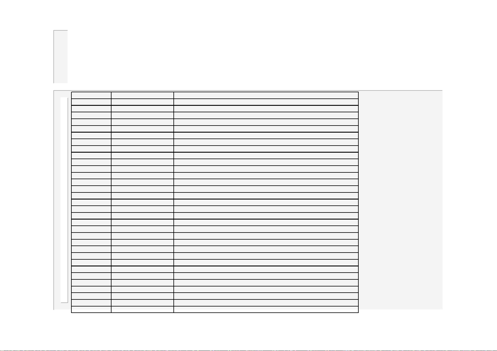
..status / error codes
A
Error code Description
97 Counter 1 end Reset counter 1
98 Counter 2 end Reset counter 2
99 Counter 3 end Reset counter 3
100 Counter 4 end Reset counter 4
101 Counter 5 end Reset counter 5
102 Counter 6 end Reset counter 6
103 Counter 7 end Reset counter 7
104 Counter 8 end Reset counter 8
105 Counter 9 end Reset counter 9
106 Counter 10 end Reset counter 10
107 Counter 11 end Reset counter 11
108 Counter 12 end Reset counter 12
109 Counter 13 end Reset counter 13
110 Counter 14 end Reset counter 14
111 Counter 15 end Reset counter 15
112 Counter 16 end Reset counter 16
113 Tip-dress 1 Dress electrodes then reset counter 1
114 Tip-dress 2 Dress electrodes then reset counter 2
115 Tip-dress 3 Dress electrodes then reset counter 3
116 Tip-dress 4 Dress electrodes then reset counter 4
117 Tip-dress 5 Dress electrodes then reset counter 5
118 Tip-dress 6 Dress electrodes then reset counter 6
119 Tip-dress 7 Dress electrodes then reset counter 7
120 Tip-dress 8 Dress electrodes then reset counter 8
121 Tip-dress 9 Dress electrodes then reset counter 9
122 Tip-dress 10 Dress electrodes then reset counter 10
123 Tip-dress 11 Dress electrodes then reset counter 11
124 Tip-dress 12 Dress electrodes then reset counter 12
125 Tip-dress 13 Dress electrodes then reset counter 13
126 Tip-dress 14 Dress electrodes then reset counter 14
127 Tip-dress 15 Dress electrodes then reset counter 15
128 Tip-dress 16 Dress electrodes then reset counter 16
dvice
28
WS2003 V1.69
Page 29
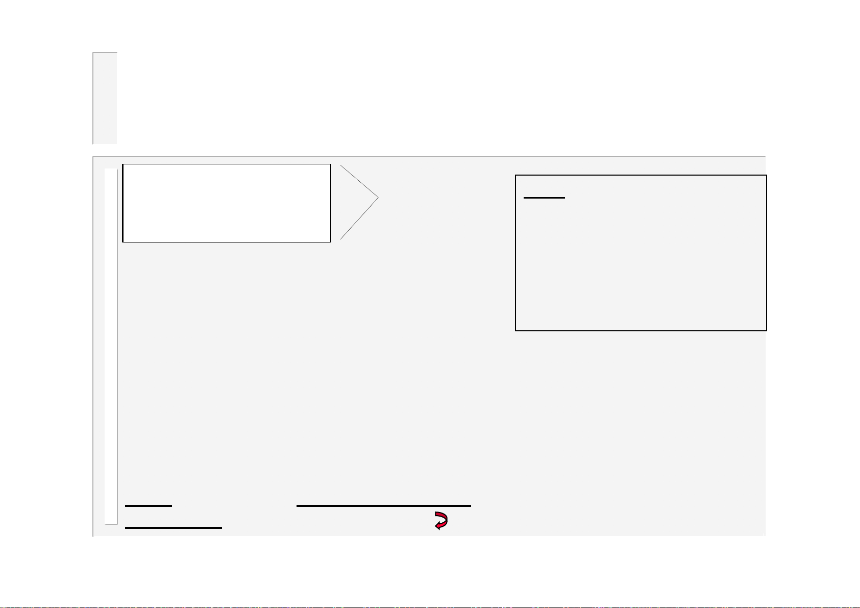
Configuration menu
<<< CONFIG. MENU>>>
EDIT CONFIGURATION
EDIT CALIBRATION
EDIT OUTPUT MAP
EDIT INPUT MAP
SET-UP ADAPTERS
BACKUP ALL DATA
RESTORE ALL DATA
INITIALISE ALL DATA
EDIT SYSTEM SETUP
Visible
window
Note: after changing the
configuration, you must restart
the timer before your changes
will take effect.
You can restart the timer by
cycling the power, or via the
system set-up menu.
Note: To access the Configuration menu, select the ‘version’ line on the
main menu (last line), hold down the key, then press the F key.
29
WS2003 V1.69
Page 30
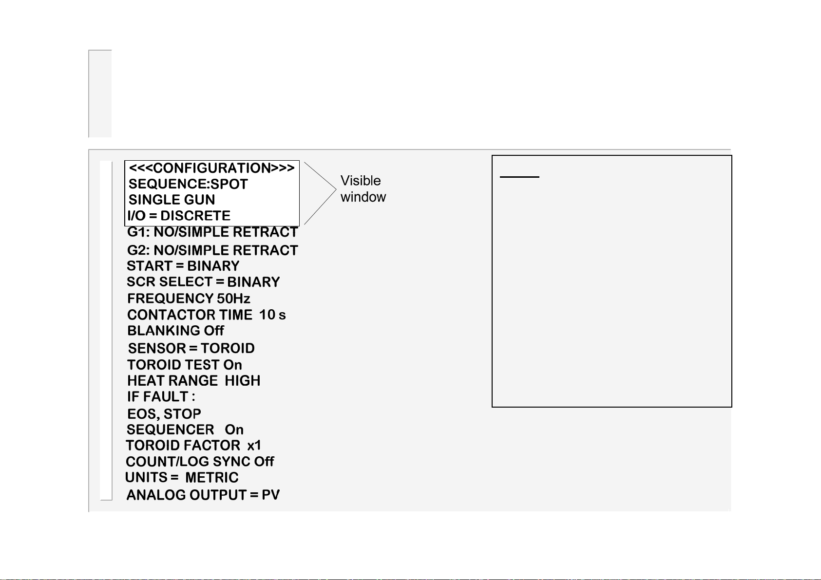
Edit configuration
Note: after changing the
configuration, you must restart
the timer before your changes
will take effect.
The diagnostic message
‘CONFIG.CHANGED’ will
appear, and further welding will
not be permitted until the timer
is restarted
You can restart the timer by
cycling the power, or via the
system set-up menu.
30
WS2003 V1.69
Page 31
…edit configuration
•Sequence:Spot / Roll-spot / Seam(2-heat) / Seam(pre-heat).
•Single gun / Dual gun / OHMA gun / Multi-gun / Multi-gun cascade: the number/type of welding guns to be
controlled.
•I/O Source:Discrete / Fieldbus(map 1) / Fieldbus(map2). Specifies how the timer obtains input signals (
outputs are always written to both the discrete and fieldbus interfaces).
•Retract:Simple / Hi-lift+ / Hi-lift- / Maintained / OHMA. Set to Simple if not required. One Independent setting
for each gun.
•Start:Binary / 1-of-4. Sets the method of program selection.
•SCR Select: Binary / 1-of-4. Sets the method of SCR selection for multi-gun modes only. Use Binary with an
external BD16 decoder, otherwise use 1 of 4.
•Frequency:AC 50 Hz / AC 60Hz / MF 50 Hz / MF 60Hz: Set to the frequency of your mains supply for AC
operation. Set to MF 50Hz for MF DC operation with a 50Hz time-base, or set to MF 60Hz for MF DC operation
with a 60Hz time-base. (Note that MF operation requires an Ethernet/MF adapter board to be fitted).
•Contactor time (0..200 s): this is the delay (in seconds) after a weld, before the contactor output is turned off.
Set to 0 if not required.
•Blanking (On/Off): When set to On, the first 2 cycles of weld current will be excluded from the measurement
and limit testing process.
•Sensor (Toroid / CT): The current can be measured via an air-cored toroid on P7, or via an iron-cored CT on
P14. Be sure to set the sensitivity correctly in the calibration file.
•Toroid test (On/Off): When set to On, the resistance of the toroid is tested while the timer is idle. The resistance
must lie between 10 and 100 Ohms. Values outside this range will prevent the timer from starting.
31
WS2003 V1.69
Page 32
……edit configuration
•Heat range (Wide/High/Low): Wide corresponds to a control range of 30-150’. High corresponds to a control range of
30-130’. Low corresponds to a control range of 50-150’. Select the LOW range for machines with a poor power factor,
or when exceptionally low currents are required. Select WIDE range for machines that need to produce both very high
and very low currents.
• If fault (Continue/Stop/Head-lock/EOS/ No EOS) :If Head-lock is selected, then when a weld fault is detected, the
weld air-valve signal is held on and no further welds are permitted, until a fault reset is given. If Stop is selected, then
when a weld fault is detected, the weld air-valve opens as normal, but no further welds are permitted, until a fault reset
is given. If Continue is selected, then further welds will be permitted, regardless of the status of the previous weld. If
EOS is selected, then the EOS signal is always given. If No EOS is selected, then no EOS signal is given when there
is a weld fault.
•Sequencer (On/Off): If On is selected, then the sequencer is active, and welds are started via sequencer statements.
If Off is selected, then the sequencer is disabled, and welds can be started via the START input.
•Toroid Factor (1..4): the ratio of the external attenuator which is required to measure currents>60kA
•Count/Log sync (On/Off): If set to On, then the log will be cleared when the counter is reset. If set to Off, then the log
and counter are independent.
•Units (Metric/Imperial): this selects the system of units (e.g kN/lbf etc.)
•Analog out (PV/Current): this selects the function on the analog output at P2. If PV is selected, then the output
follows the setting of the PV parameter in the programmes. If Current is selected, then the output will be the
measured current waveform. Scale factors for both functions are set in the calibration file. Note that the output is
provided as 0..10V or 4..20mA, depending on the setting of pcb jumper J4/J5.
32
WS2003 V1.69
Page 33
Edit calibration
<<< CALIBRATION 1 >>>
TOROID: 150 mV/kA
S/P RATIO 50:1
S/P OFFSET 0 A
PRESSURE:
Pt1: 10.0kN @ 100%
Pt2: 0.00kN @ 0.0%
INVERTER:
Pt1: 15.1kA @ 80.0%
Pt2: 6.45kN @ 20.0%
ANALOG: 10V = 10kA
AN.IN GAIN x1.000
AN.IN OFFSET +0.00 V
CCR GAIN (SEAM): 5
Note: there are two separate calibration files
for each gun in a dual-gun system, and
sixteen calibration files in a multi-gun system.
Only if MF mode
selected
Visible
window
•Toroid: sensitivity of the measuring coil
(toroid), expressed in mV/kA.
•S/P ratio & Offset: See next page for
details.
•Pressure: relationship between the PV
controller output and actual tip force. This is
expressed by entering two ‘test’ point values,
which then define a straight-line relationship.
•Inverter: relationship between the %heat
output and actual current. This is expressed
by entering two ‘test’ point values, which then
define a straight-line relationship. (Only
required for MF mode).
•Analog: the value of current which
corresponds to full scale (10V/20mA) from
the analog output at P2.
•Analog in gain: value by which the voltage
at the analog input (ch 3 only) is multiplied.
Use to fine trim the reading, or to match a 5V
sensor with the 10V input scale.
•Analog in offset: value of the voltage at the
analog input (ch 3 only) for a zero reading.
Use in conjunction with the gain parameter to
match reading to an external meter.
•CCR gain (Seam): Adjusts the CCR gain for
seam welds only. Set to 5 as a starting point.
33
WS2003 V1.69
Page 34
…calibration
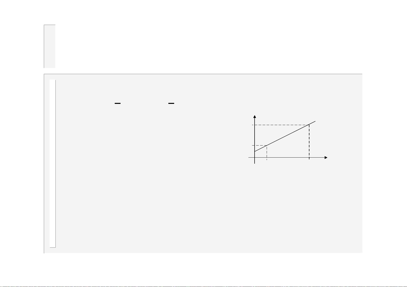
•If the sensor (Toroid or CT) is measuring the primary current (AC modes
only), the timer can display secondary values. It does this by calculation
based on the S
econdary to Primary ratio (S/P ratio) and offset (S/P offset)
parameters. For MF operation set S/P ratio to 1:1, and set S/P offset to 0.
I
•To determine the correct values,
s
I
s2
do the following:
I
s1
• Set the S/P ratio to 1:1 in the calibration.
I
• Set the S/P offset to 0 in the calibration.
I
p1
I
p2
p
• Do a short circuit weld at a low heat in PHA mode, and measure the
secondary current (I
)with a meter. Note the corresponding value (Ip1)
s1
on the timer status screen.
• Do a short circuit weld at a high heat in PHA mode, and measure the
secondary current (I
)with a meter. Note the corresponding value (Ip2)
s2
on the timer status screen.
• Calculate and enter S/P ratio = (I
-Is1) / (Ip2-Ip1)
s2
• Calculate and enter S/P offset = Is2-(Ip2x S/P ratio)
34
WS2003 V1.69
Page 35
……calibration
•If you do not have a suitable meter, or you do not wish to do the
calculations, you can still use primary feedback by doing the following:
1. Set the S/P ratio = transformer turns ratio in the calibration.
2. Set the S/P offset to 0 in the calibration.
•If you do not know the transformer turns ratio, then use a value of 50:1 as
many welding transformers will be approximately this figure.
• The current readings on the timer will be shown in kA, and the timer will
regulate (in CCR mode) to these figures, but they will not tie-up with a meter
(i.e. the numbers are not absolute, but in ‘scaled’ Amps).
If you require precise and absolute settings then you must either:
•Do the procedure and calculations (see previous page)
OR
•Use secondary feedback from a toroid, and set the sensitivity
correctly.
35
WS2003 V1.69
Page 36
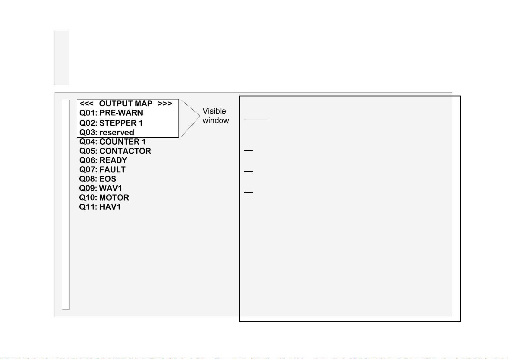
Edit Output Map
Each output may be independently set up as
either
or
or
or
When an output is mapped to ‘event’, it may be
programmed to operate at any point in the
welding sequence, via an event program.
When an output is mapped to ‘sequencer’, it may
be programmed to operate under the control of
the sequencer program.
When an output is mapped to ‘fieldbus’, it will be
:
• the standard function assigned (see
users connections).
• as an EVENT output.
• as a SEQUENCER output.
• as a FIELDBUS output (outputs 1-8 only).
operated under the direct control of the fieldbus
inputs.
36
WS2003 V1.69
Page 37
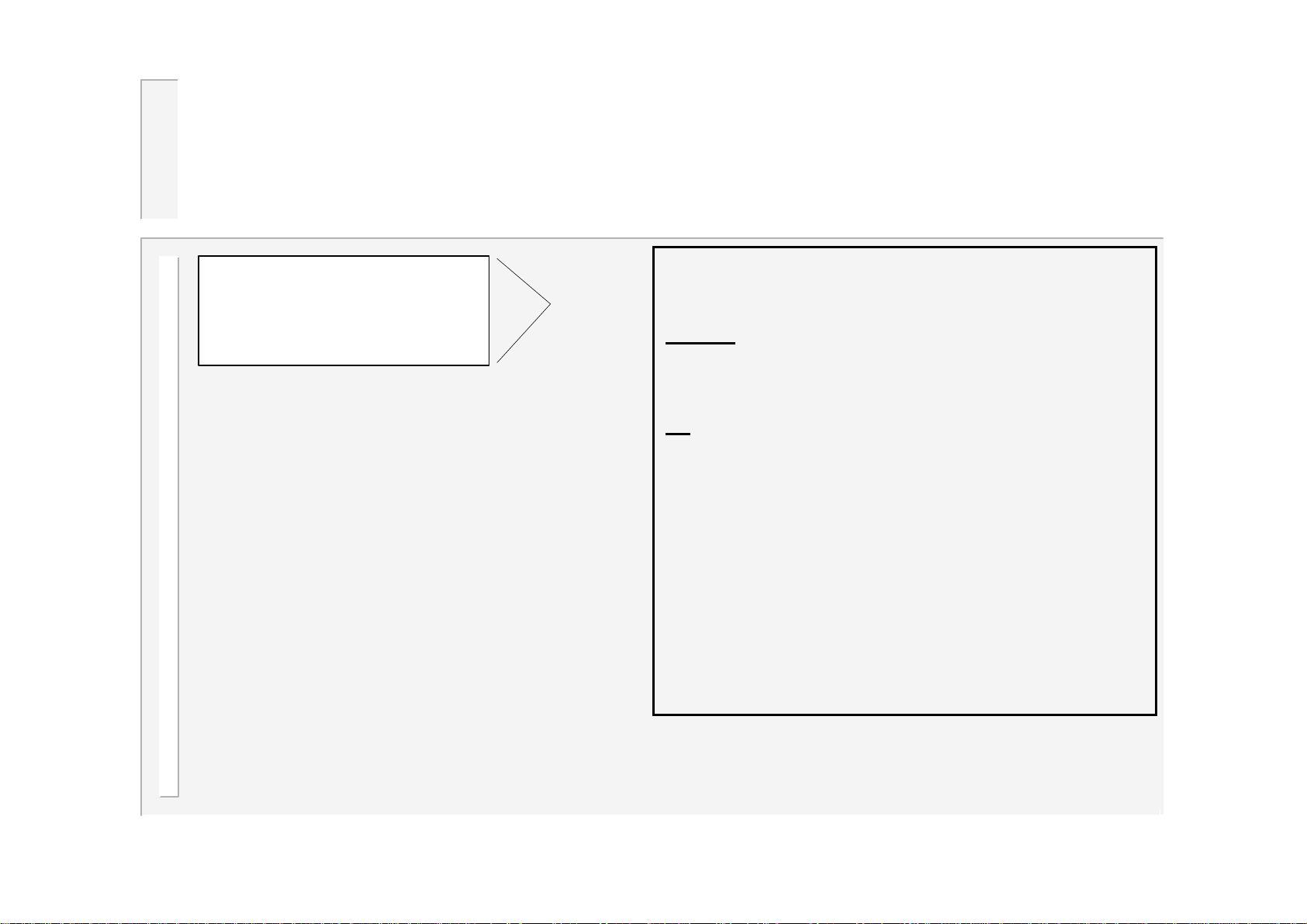
Edit Input Map
<<< INPUT MAP >>>
I01: RESET FAULT
I02: P32
I03: P16
I04: EDIT DISABLE
I05: RESET COUNT
I06: RESET STEPPER
I07: 2nd STAGE
I08: RETRACT
I09: START 1
I10: P8/START 2
I11: P1/START 3
I12: P2/START 4
I13: P4
I14: WELD ON
Visible
window
Each input may be independently set
up as
either
:
• the standard function assigned
(see users connections).
or
• as a SEQUENCER input.
When an input is mapped to
‘sequencer’, it may be used as part of
the sequencer program, or as a
discrete input to the fieldbus.
Note that inputs I09 and I14 have
special functions, and may only be
mapped to standard.
37
WS2003 V1.69
Page 38
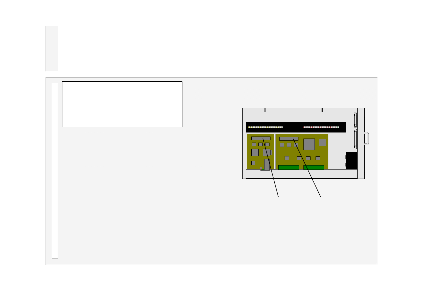
Set-up Adapters
<<< ADAPTERS >>>
SLOT 1 Ethernet 1.00
SLOT 2 NO ADAPTER
The WS2003 timer can be fitted with up to two
adapter cards, to provide additional functions.
These are fitted into two positions, referred to as
slot 1 and slot 2.
This screen can be used to:
•Show what type of adapter cards are fitted.
•Access any parameters required by that adapter.
Note that some adapters do not require any
parameters.
View of timer with cover removed
and two adapter cards fitted.
Slot 1 Slot 2
38
WS2003 V1.69
Page 39
Backup/Restore
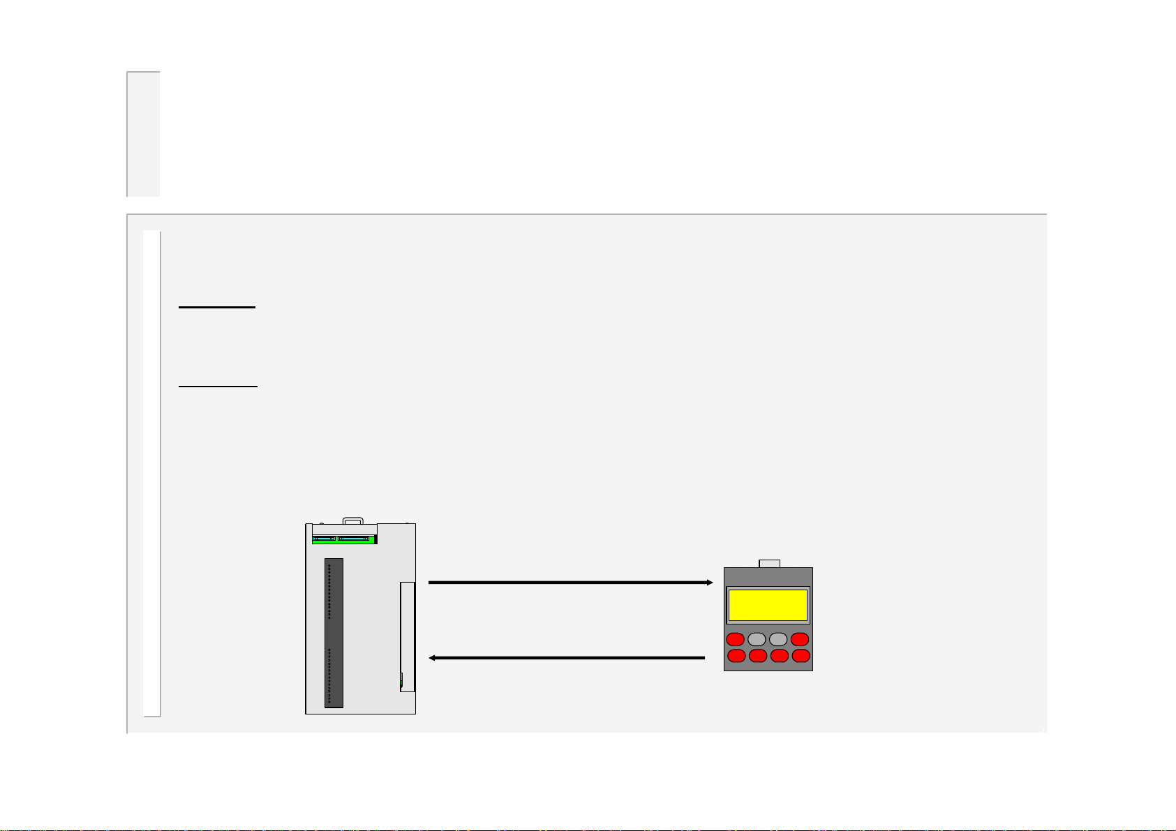
The Backup and Restore functions provide a convenient means of transferring all of your settings
from one timer to another.
Backup: Use this function to make a copy of all of your data. The copy is held within the WSP3
pendant. No data in the timer is changed. Note that only one backup can be stored in the WSP3,
and that this is overwritten each time the backup function is used.
Restore:
pendant. Note that this operation will overwrite all data which was previously stored in the timer.
After the restore operation, the backup remains in the WSP3.
Before the restore can proceed, a check is made to ensure that the backup data was recorded from
the same type of timer (i.e. another WS2003).
Use this function to restore all of your data in the timer, from a backup stored in the WSP3
Backup
WSP3WS2003
Restore
39
WS2003 V1.69
Page 40
Initialise all data
The Initialise function provides a convenient means of setting all of the data in the
timer to a known initial state. This can be useful when first setting up a system.
Caution: When you use the Initialise
function, you will loose all previously
stored data in the timer.
After an initialise operation, you should edit the configuration files (configuration,
calibration, mapping etc.), to suit your installation. You will then need to set-up any
welding programmes etc. which you wish to use.
40
WS2003 V1.69
Page 41
System set-up menu
<<< SYSTEM SETUP >>>
SHOW SYSTEM FILES
SELECT ACTIVE FILE
RESTART SYSTEM
Caution: These functions should only
be used by trained and experienced
personnel, as improper use could
render the timer inoperable.
The WELDSTAR model WS2003 is equipped with two
memories, which can be used to store two versions of the
operating firmware files. The Edit system set-up menu
provides a number of functions for examining and
selecting these files.
Note: The timer will not operate while this menu is selected.
41
WS2003 V1.69
Page 42
Main menu
<<< MAIN MENU >>>
USE PROGRAM -EXT( 0)
EDIT PROGRAM FILE
EDIT LIMITS FILE
EDIT EVENTS FILE
ELECTRODE MENU
SEQUENCER MENU
WELD LOG
COPY PROGRAM
I/O STATUS
FIELDBUS INPUTS
For information only
ANALOG STATUS
WS2003 VERSION 1.34
Note: To access the Configuration menu, select the ‘version’ line on the main menu
(last line), hold down the key, then press the F key.
42
WS2003 V1.69
Page 43
Edit program (AC)
<<< PROGRAM 0 >>>
I1=7.50kA 25.0% PHA
I2=10.0kA 50.0% CCR
[email protected]% NORM
PSQ= 0 SQZ= 10
W1 = 0 C1 = 0
W2 = 10 C2 = 0
Pulses(W2-C2) = 1
UPSLOPE = 3
DOWNSLOPE = 0
HOLD = 10
OFF = 0 (SINGLE)
Visible
window
PHA=Phase angle mode. The current and
heat parameters are independently
adjustable. No current regulation takes
place. The current parameter is used for
monitoring only.
CCR=Constant current regulation mode.
The current parameter is adjustable, but the
heat is automatically determined by the
timer, as it regulates the current to the set
level.
IMPORTANT!
Set OFF time to 0 for single spot operation. If OFF time>0, then r epeat operation will
occur.
43
WS2003 V1.69
Page 44
Edit program (MF)
<<< PROGRAM 0 >>>
I1=7.50kA 25.0% UNC
I2=10.0kA 50.0% CAL
[email protected]% NORM
PSQ= 0 SQZ= 10
W1 = 0 C1 = 0
W2 = 10 C2 = 0
Pulses(W2-C2) = 1
UPSLOPE = 3
DOWNSLOPE = 0
HOLD = 10
OFF = 0 (SINGLE)
Visible
window
UNC=Uncalibrated mode. The current and
heat parameters are independently
adjustable. Actual current is determined by
the inverter. The current parameter is used
for monitoring only.
CAL=Calibrated mode. The current
parameter is adjustable, but the heat is
automatically determined by the timer from
the calibration data.
IMPORTANT!
Set OFF time to 0 for single spot operation. If OFF time>0, then r epeat operation will
occur.
44
WS2003 V1.69
Page 45
..edit program
<<< PROGRAM 0 >>>
I1=7.50kA 25.0% PHA
I2=10.0kA 50.0% CCR
[email protected]% NORM
PSQ= 0 SQZ= 10
W1 = 0 C1 = 0
W2 = 10 C2 = 0
Pulses(W2-C2) = 1
UPSLOPE = 3
DOWNSLOPE = 0
HOLD = 10
OFF = 0 (SINGLE)
IMPORTANT!
Set OFF time to 0 for single spot
operation. If OFF time>0, then
repeat operation will occur.
Visible
window
NORM = normal spot weld operation. LINK =
linked spot operation.
LINKed operation provides a means of
chaining programmes together so that a
single start signal generates a sequence of
programmes. At the end of a linked program,
the next program (numerically ascending) is
automatically selected and run, and so on,
until either a program set to NORMal, or the
last program (63) is reached.
Note: If the low-force option is selected in the
configuration, then the presqueeze (PSQ) parameter
changes to low-force time (LF). See section ‘low-force
approach’.
If the OHMA system is selected, additional timing
parameters will be shown.
45
WS2003 V1.69
Page 46
….edit program(seam)
<<< PROGRAM 0 >>>
I1=7.50kA 25.0% PHA
I2=10.0kA 50.0% CCR
BALANCE = 4.5%
[email protected]%
PSQ= 0 SQZ= 10
W1 = 0 C1 = 0
W2 = 10 C2 = 0
UPSLOPE = 3
DOWNSLOPE = 0
HOLD = 10
If the timer is configured for seam welding, then the program screen
Visible
window
BALANCE : This control is used to
balance the current when using pulsed
seam welding. It may be adjusted
dynamically (i.e. while the machine is
running).
changes as shown above, in order to present only the relevant
parameters..
46
WS2003 V1.69
Page 47
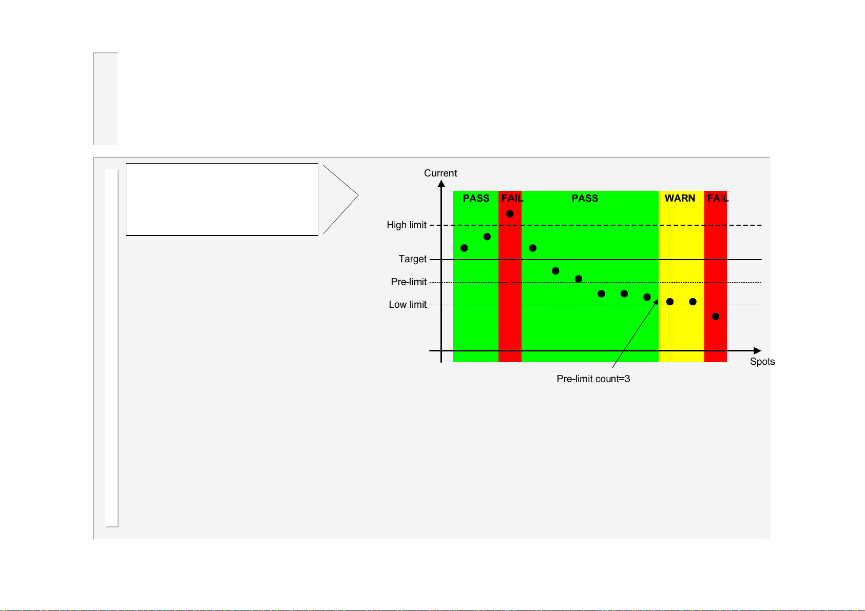
Edit Limits
<<< LIMITS PROG 0 >>>
CURRENT: MONITOR On
LOW1=15% HIGH1=10%
PRE-LIMIT1= 5%
LOW2=10% HIGH2= 8%
PRE-LIMIT2= 5%
PRE-LIMIT COUNT = 3
RETRY On
PRESSURE: MONITOR On
WAIT On
LOW = 10% HIGH=10%
Visible
window
•The PRE-LIMIT COUNT is the number of successive welds which can fail the pre-limit level test,
before a warning is generated.
•If RETRY is On, then in the event of the monitor detecting low or no current, the timer will
automatically re-weld, without opening the electrodes.
•Pressure: monitor Pressure is checked to be within limits at the end of the weld.
•Pressure: wait Pressure is checked to be within limits before weld is allowed to start.
47
WS2003 V1.69
Page 48
Edit Events
<<< EVENTS PROG 0 >>>
Ev1: 1=on @SQZ + 2
Ev2: 1=off @HLD + 5
Ev3: 6=on @W1 + 5
Ev4: 6=off @W2 + 3
e.g. Turn on output 6,
5 cycles into the
Weld 1 interval.
All event outputs will be turned off at the end of the
weld program.
Visible
window
•Each welding program
may have up to 4
events defined.
•Each event can turn
one output on or off.
•To disable an event,
set it’s output to ‘?’.
Note:The outputs used
must be mapped to
‘EVENT’ for correct
operation.
(see Edit Output Map)
An ‘Event’ can only occur during a welding program.
For actions required outside the welding program,
use the sequencer.
48
WS2003 V1.69
Page 49
Electrode menu
<< ELECTRODE MENU >>
STEPPER STATUS
EDIT STEPPER
EDIT COUNTER FILE
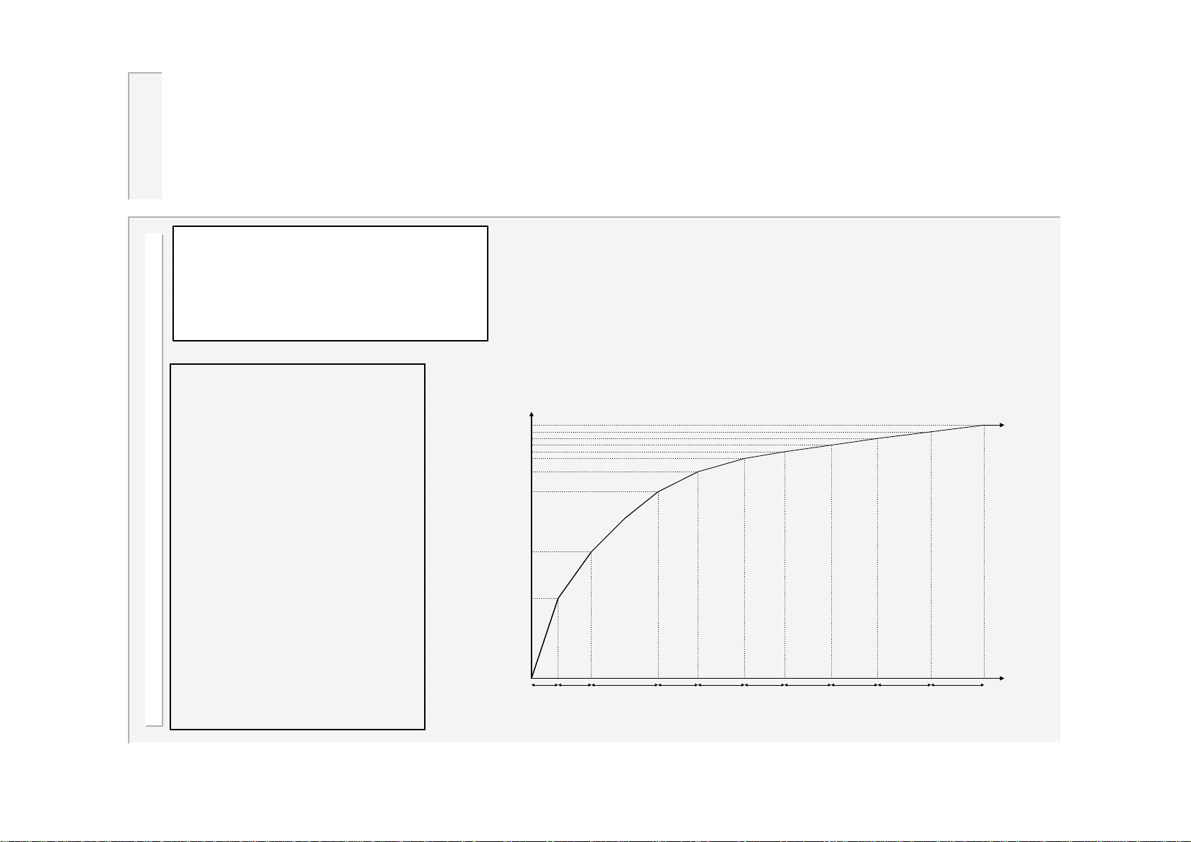
A stepper is
programmed by
means of a curve
which will provide
values of heat and
current increments,
related to the number
of spots done. The
curve is defined by a
set of 10 points. The
Electrode management is provided via a combination
of stepper and counter functions.
The stepper provides a means of gradually increasing
the current, to compensate for electrode wear. One
stepper is provided per gun.
Current or Heat
dH9/dI
9
dH4/dI
4
dH3/dI
3
dH2/dI
2
dH1/dI
1
dH0/dI
0
timer provides
interpolation between
these points.
Step 0 Step 1 Step 2 Step 3 Step 4 Step 5 Step 6 Step 7 Step 8 Step 9
49
WS2003 V1.69
Spots
Page 50
Stepper status
<STATUS ELECTRODE 1>
SPOTS DONE= 45
[RESET] 12%
dH= 2.5% dI= 5.0%
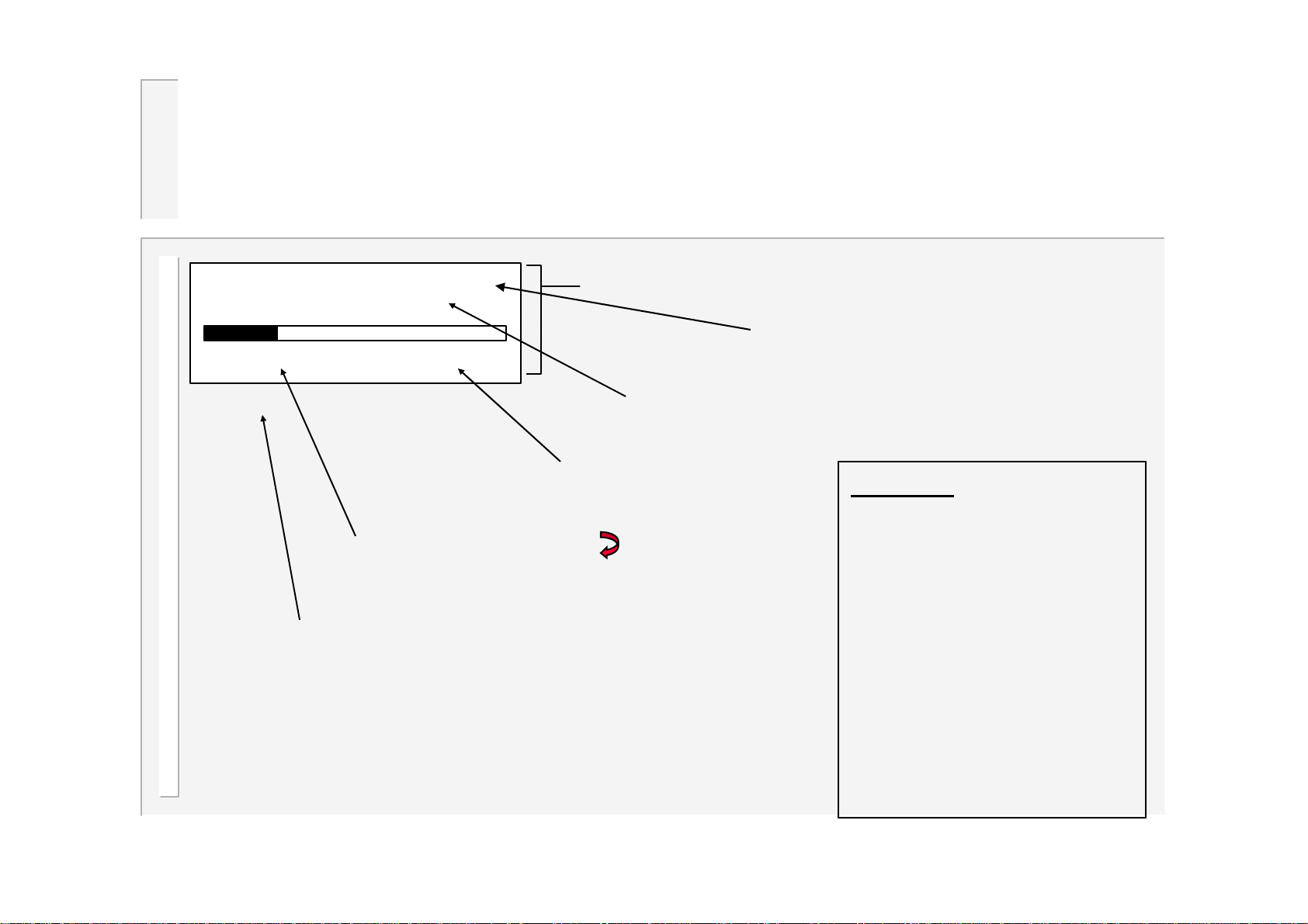
The percentage done of the total number
of spots, also shown as a bar-graph.
Select this field and press to reset this
stepper (same function as external input).
dH = % of programmed heat being added
dI = % of programmed current being added.
Visible
window
Select gun (electrode).
The number of spots made since the
last reset. This may be changed to
alter the working position on the curve.
Outputs:
Output ‘End of stepper’
comes on at the end of
the last step.
Output ‘Prewarn’ comes
on during the last step.
If tip-dressing is on, then
50
the outputs behave
differently (see edit
counter).
WS2003 V1.69
Page 51
Edit stepper
<<< STEPPER 1 on >>>
CONTINUE AT END
SPOTS +HEAT +AMPS
0: 10 1.0% 2.5%
1: 50 1.5% 5.0%
2: 100 2.0% 7.5%
3: 100 2.5% 10.0%
4: 100 3.0% 12.5%
5: 100 3.5% 15.0%
6: 100 4.0% 17.5%
7: 100 4.5% 20.0%
8: 150 5.0% 22.5%
9: 200 5.5% 25.0%
[PRESET #1]
Visible
window
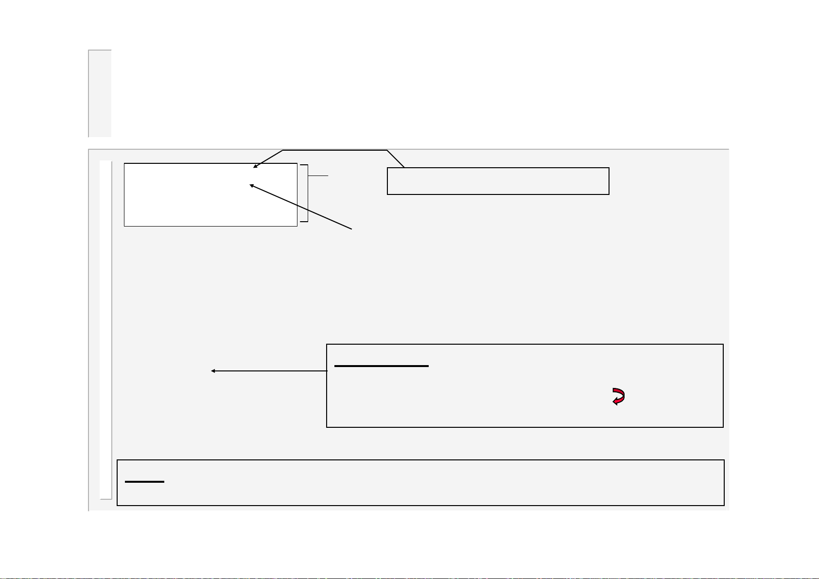
Enable or disable the stepper.
If continue at end is selected, then at the end of
the last step,further welding can take place as
normal, but the stepper output will remain on. There
is no further increase in current.
If stop at end is selected, then no further welding
may take place until a stepper reset is given.
Quick set-up: Enter values in step 9 only, to define the
finishing point, select the PRESET field, edit the preset
number(see next page), and then press to load this
stepper with a preset curve.
Note: PHA mode will make use of both the +HEAT(dH) and +AMPS(dI) parameters.
CCR mode uses only the +AMPS(dI) parameter, as the heat is self-adjusting.
51
WS2003 V1.69
Page 52
Stepper presets
60.0
50.0
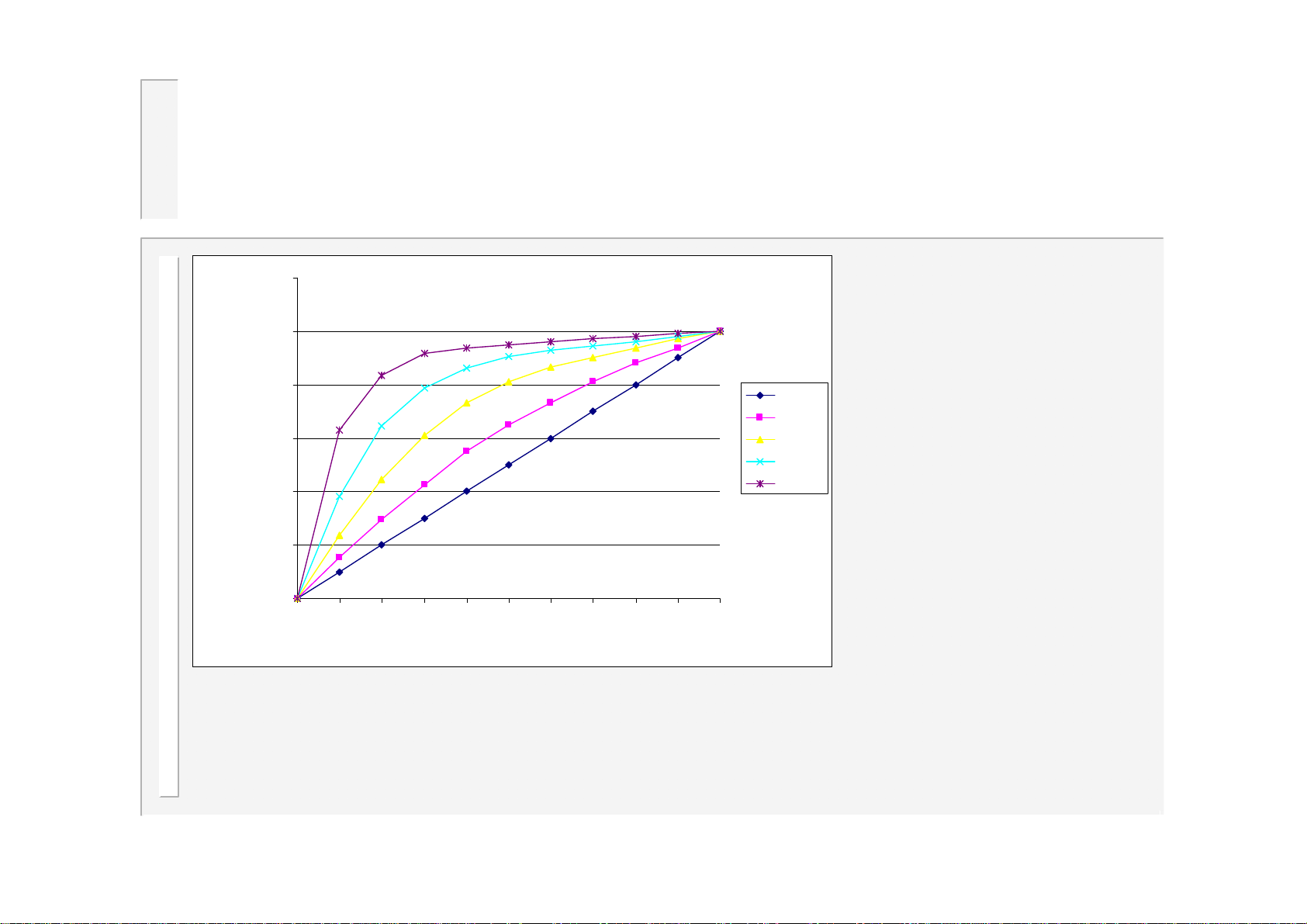
When a preset curve is
loaded, the data is
dH/DI %
40.0
30.0
20.0
10.0
0.0
012345678910
step no.
Series1
Series2
Series3
Series4
Series5
obtained from a table
which holds the 5 curves
shown.
The step sizes (spots) are
all made the same as for
step 9, and the +HEAT(dH)
and +AMPS(dI) parameters
are obtained by applying
the values in step 9 to the
curve as a scaling factor.
52
WS2003 V1.69
Page 53
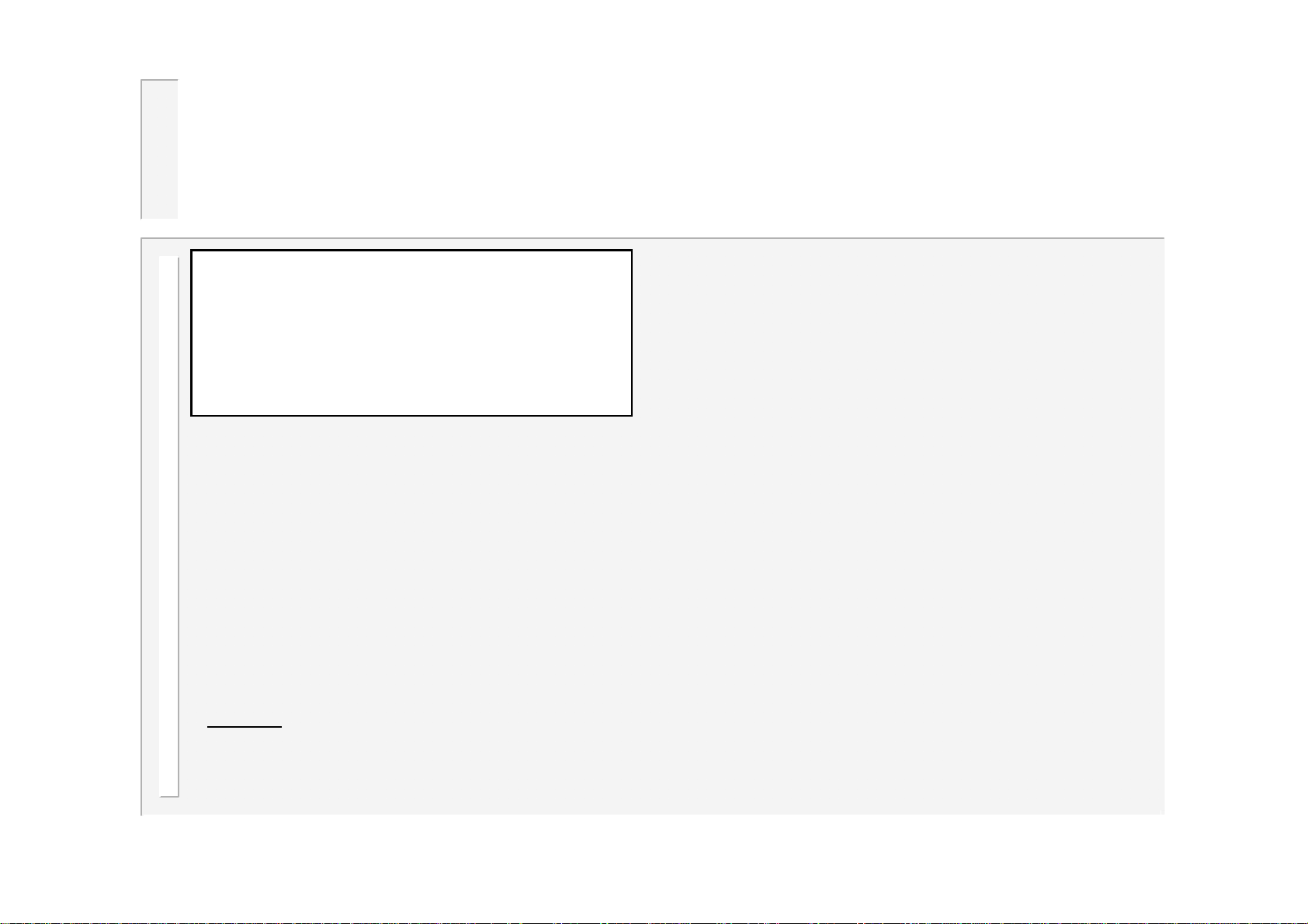
Edit counter
<<< COUNTER 1 >>>
COUNT NOW = 431
COUNT UP TO 500
STOP AT END
TIP DRESSING On
MAX.DRESSINGS = 10
DRESSINGS DONE = 2
@RESET,STEPPER= 100
DRESS WHEN NEW On
Note:
gun/electrode 1, counter 2 is used
Counter 1 is used by
Count now is incremented after
every weld. When count up to is
reached, the counter output is
activated.
Set count up to = 0 to disable a
counter.
If stop at end is selected, then no
further welding may take place until
a counter reset is given.
If continue at end is selected, then
further welding can take place as
normal, but the counter output will
remain on.
Count now is reset to zero by
activating the counter reset input.
by gun/electrode 2, etc.
53
WS2003 V1.69
Page 54
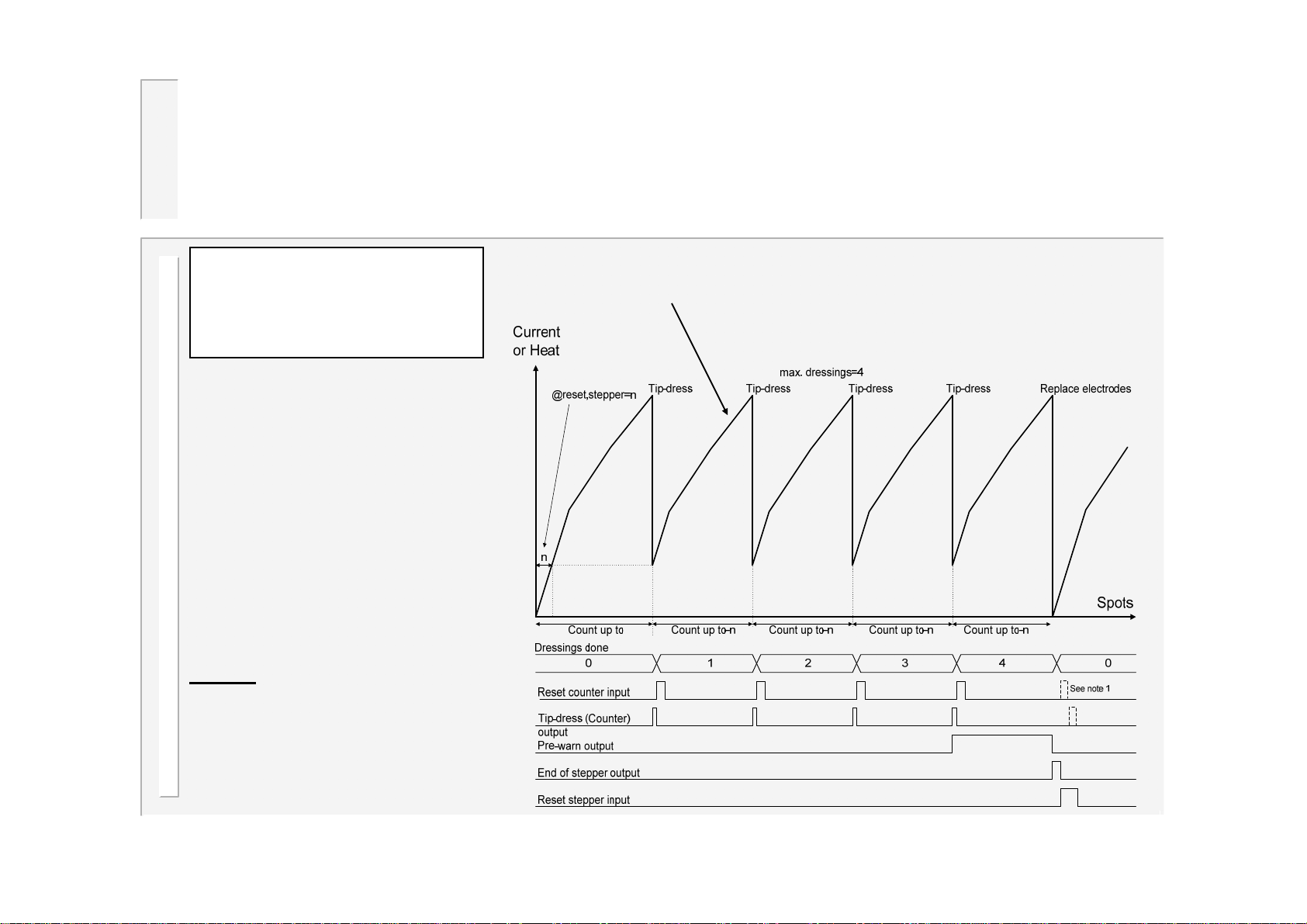
..edit counter(tip dressing)
<<< COUNTER 1 >>>
COUNT NOW = 431
COUNT UP TO 500
STOP AT END
TIP DRESSING On
MAX.DRESSINGS = 10
DRESSINGS DONE = 2
@RESET,STEPPER= 100
DRESS WHEN NEW On
The counter can be used to
control tip-dressing by setting the
parameter ‘tip-dressing’to On.
Note 1
set to On, then the tip-dress
(counter) output will also be
activated after a reset stepper
operation. This facilitates the
dressing of new electrodes.
: If ‘dress when new’is
Stepper curve (see edit stepper)
54
WS2003 V1.69
Page 55
Sequencer
The sequencer provides a means of controlling a small machine, via a series of logic statements.
The statements are executed sequentially in the order in which they appear.
The START1 input is used to trigger execution of the sequence, and must be maintained. On
release of the START1 signal, the sequence is reset.
With the sequencer configured (see edit configuration), the START1 signal cannot be used to start
a weld. Instead, welds are started via statements within the sequence.
The functions available consist of various input, output, memory, delay, counter and weld
operations. It is also possible to program subroutines up to 8 levels deep.
The following resources are available:
Statements(lines) Up to 249 max.
Outputs 8 Q1 to Q8
Inputs 16 I01 to I16
Memory 8 M1 to M8 (non-volatile)
Counters 8 C1 to C8 (non-volatile)
Analog inputs 3 A1 to A3
Non-volatile values are retained,
even if power is lost.
Note that the inputs and outputs are
shared with the welding controller
and event timer
(see Input map and Output map).
55
WS2003 V1.69
Page 56
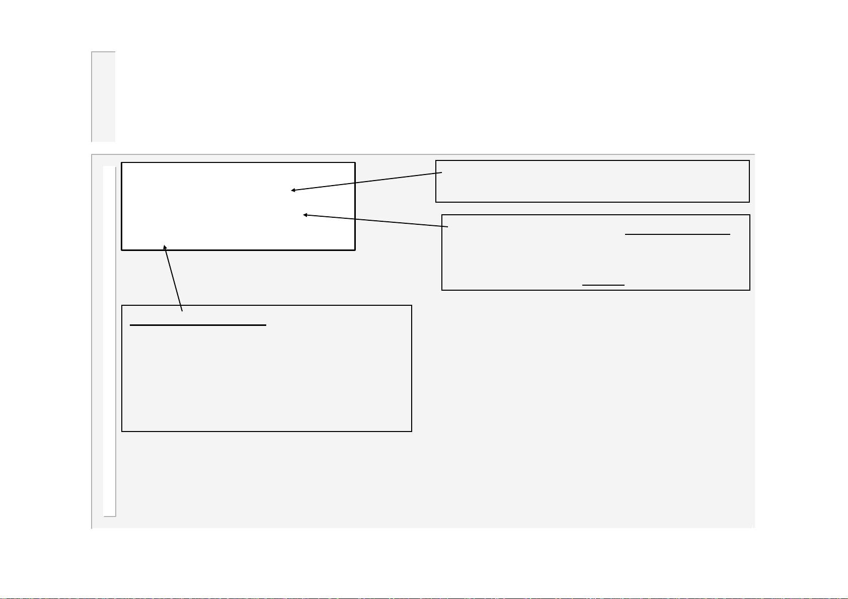
Sequencer Menu
<< SEQUENCER MENU >>
EDIT SEQUENCE
ERASE SEQUENCE
STATUS: IDLE
For information only:
Off: the sequencer is turned off (see edit
configuration)
Idle:the sequencer is turned on, and waiting
for the START input.
Line n: the sequence is running and is
executing line n.
Enter new statements, parameters etc. ,or edit
the existing sequence (see edit sequence).
Erase the entire sequence –use with caution!
You will be asked to confirm the operation
before the erase takes place.
An erased sequence cannot
be restored.
56
WS2003 V1.69
Page 57
…edit sequence
On the edit sequence screen, the keys have the following functions:
At any time:
•Press the or keys to change the selected line. The entire line will flash. The
screen will scroll when required.
•Press the key to insert a new (blank) line. The line number will be shown.
•Press the F key to return to the sequencer menu screen.
When entire line is flashing:
•Press + and – together to delete the selected line
•Press the + or - keys to alter the selected statement type.
•Press the key to momentarily see the selected line number.
•Press the or keys to select a parameter (parameter only will flash).
When parameter only is flashing:
•Press the + or - keys to alter the selected parameter.
•Press + and – together to set 0 or minimum value.
57
WS2003 V1.69
Page 58
…..edit sequence
The following table lists the available logic statement types:
Statement Range Function
Line nnn
----- STEP nnn ----AWAIT INPUT In n ON
AWAIT INPUT In n OFF
OUTPUT Qn ON
OUTPUT Qn OFF
MEMORY Mn ON
MEMORY Mn OFF
DELAY nn.n s
JUMP nnn
GOSUB nnn
RETURN
COUNTER Cn = xxx
DECREMENT COUNTER Cn
IF Cn>ZERO, JUMP xxx
IF Qn ON, JUMP xxx
IF Qn OFF, JUMP xxx
IF Mn ON, JUMP xxx
IF Mn OFF, JUMP xxx
IF Inn ON, JUMP xxx
IF Inn OFF, JUMP xxx
WELD (Prog=nn)
1..249 Li ne number within sequencer file ( has no ef fect)
1..999 Has no effect, but serves as the tar get for a JUMP or G OSUB statement, or as a logical divider in the progra m
1..14 Waits for Input nn to be ON
1..14 Waits for Input nn to be OFF
1..12 Turns ON Output n
1..12 Turns OFF Output n
1..8 Sets Memory bit n (non-volatile)
1..8 Clears Memory bit n (non-volatile)
0.1..99. 9 s W aits for specifi ed t ime
1..999 Pro gr am conti nu es at specifi ed S TEP numb er .
1..999 Program continues with the subroutine at the specified STEP number. (Note maximum of 8 nesting levels)
Return from subroutine
n=1..8, x=1..999 Load s Counter n with the value xxx (non-volatile)
1..8 The value in Counter n is reduced by 1 (non-volati le)
n=1..8, x=1..999
n=1..12, x=1. .999
n=1..12, x=1. .999
n=1..8, x=1..999
n=1..8, x=1..999
n=1..14, x=1. .999
n=1..14, x=1. .999
n=0..63,EXT
If the value in Counter n is not
If the value in Counter n is
If Output Qn is ON
If Output Q n i s OFF , t hen conti nue at the nex t statement
If Output Qn is OFF
If Output Qn is ON, then continue at the next statement
If Memory Mn is ON
If Memory Mn i s OFF , t hen conti nue at the nex t statement
If Memory Mn is OFF
If Memory Mn i s ON, then continue at the next statement
If Input Inn is ON
If Input Inn is OFF, then continue at the ne xt stat ement
If Input Inn is OFF
If Input Inn is ON, then continue at the next statement
Execute weld sequence. The program number is determi ned by t he parameter nn. If nn=EXT, then the program
number is read from the external selection inputs.
The sequencer will wait untill the weld reaches 'End of sequence', before continuing with the next statem ent.
, then continue at STEP xxx.
, then continue at STEP xxx.
, then continue at STEP xxx.
, then continue at STEP xxx.
, then continue at STEP xxx.
then continue at STEP xxx.
zero, then continue at STEP xxx.
zero, then continue at the next statement
58
WS2003 V1.69
Page 59
Example sequence
Statement Range Function
AWAIT ANALOG n<mm V
AWAIT ANALOG n>mm V
IF ANALOG n<mm V, JUMP xxx
IF ANALOG n>mm V, JUMP xxx
n=1.3,
0.0<=mm<=10.0
n=1.3,
0.0<=mm<=10.0
n=1.3,
0.0<=mm<=10.0
n=1.3,
0.0<=mm<=10.0
A short example program:
----- ST EP 1 ----AWAIT INPUT I03 ON
----- ST EP 2 ----OUTPUT Q8 ON
DELAY 0. 5
----- ST EP 3 ----WELD (Prog = 01)
OUTPUT Q8 OFF
----- ST EP 4 ----OUTPUT Q7 ON
DELAY 0. 4
OUTPUT Q7 OFF
DELAY 0. 2
JUMP 4
Waits for An alog input n t o be less than mm Volts.
Waits for Analog input n t o be greater than mm Volts.
If Analog input n is less than mm Volts, then continue at STEP xxx, otherwise continue with the next statement.
If Analog input n is greater than mm Volts, then continue at STEP xxx, otherwise continue with the next
statement.
Part detector
Clamp ON
Pause
W eld operat i on us i ng program number 1
Clamp off
Signal j ob done by flas hi ng out put unt i l S TART released
Flash 'On' t i m e
Flash 'Off' tim e
Loop back to c reat e flas hi ng effect
59
WS2003 V1.69
Page 60
Weld log
<<< WELD LOG >>>
64 welds in log
VIEW LOG
CLEAR LOG
The number of welds
presently held in the log.
The timer records the currents
from each weld into the weld log.
The log can hold information from
up to 64 welds (after this, the
oldest record will be discarded).
To see the information for each
weld, select the VIEW LOG
function.
The log can be cleared (emptied)
by using the CLEAR LOG
function.
60
WS2003 V1.69
Page 61
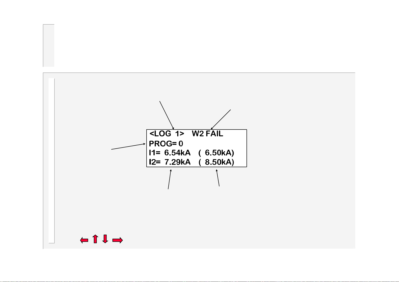
View log (screen 1)
Press the + or - keys to
select the log record
( 1= most recent weld,
64= oldest weld).
Program used
for this weld
Status for this weld
Actual current measured
Note that if either of I1 or I2 are not shown, then that interval was not used.
•Press to change to log screen 2.
Target current from program
61
WS2003 V1.69
Page 62
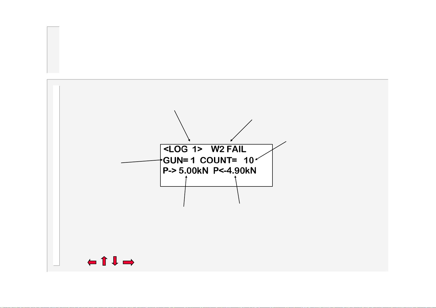
View log (screen 2)
Press the + or - keys to
select the log record
( 1= most recent weld,
Status for this weld
64= oldest weld).
Gun (electrode)
used for this
weld
PV output
•Press to change to log screen 1.
Measured PV feedback
Value of the counter
used for this weld
62
WS2003 V1.69
Page 63
Copy program
<<< COPY PROGRAM >>>
FROM: 0
Copy a program (and associated
limit and event files) to any other
program, or to all other
TO: 1
programmes.
GO
•Press the + or - keys to alter the selected parameter. The TO parameter can
be set to ALL if required (i.e. copy 1 program to all others).
•Select the last line ( GO ), then press the key to execute the copy function.
This line will briefly show COPY DONE, when the function is complete.
63
WS2003 V1.69
Page 64
Copy electrode
<<<COPY ELECTRODE>>>
FROM: 1
Copy a stepper (and associated
counter and calibration files) to
any other stepper, or to all other
TO: 2
steppers.
GO
•Press the + or - keys to alter the selected parameter. The TO parameter can
be set to ALL if required (i.e. copy 1 stepper to all others).
•Select the last line ( GO ), then press the key to execute the copy function.
This line will briefly show COPY DONE, when the function is complete.
64
WS2003 V1.69
Page 65
I/O Status
<<< I/O STATUS >>>
I01:RESET FAULT Off
I02:P32/GAPSW. On
I03:SEQUENCER On
I04:EVENT Off
I05:RESET COUNT Off
I06:RESET STEPPER Off
....
....
etc.
Visible
window
This screen can be used to observe the
status of the discrete inputs and outputs.
Each input or output is labeled to show
how it is mapped.
i.e. standard function / event / sequencer.
(see edit input map and edit output map)
65
WS2003 V1.69
Page 66
Fieldbus input status
<<< BUS INPUTS >>>
B00:START1 Off
B01:START2 On
B02:START3 Off
B03:START4 Off
B04:2nd STAGE Off
B05:WELD ON Off
....
....
etc.
Visible
window
This screen can be used to observe the
status of the fieldbus inputs.
Note that this screen is only available if
the timer is configured for fieldbus
operation.
66
WS2003 V1.69
Page 67
Analog Status
<<< ANALOG STATUS >>>
Channel 1 = 0.00 V
Channel 2 = 2.34 V
Channel 3 = 9.55 V
TOROID R = 20
•Analog input channels
voltage at each of the analog inputs.
•Toroid resistance
toroid test, in Ohms. If a
measurement>750 Ohms is obtained
then the (infinity) symbol is shown. If the
toroid test is off, then ??? is shown
: the result of the
: the dynamic
This screen can be
used to observe the
status of the analog
inputs.
67
WS2003 V1.69
Page 68
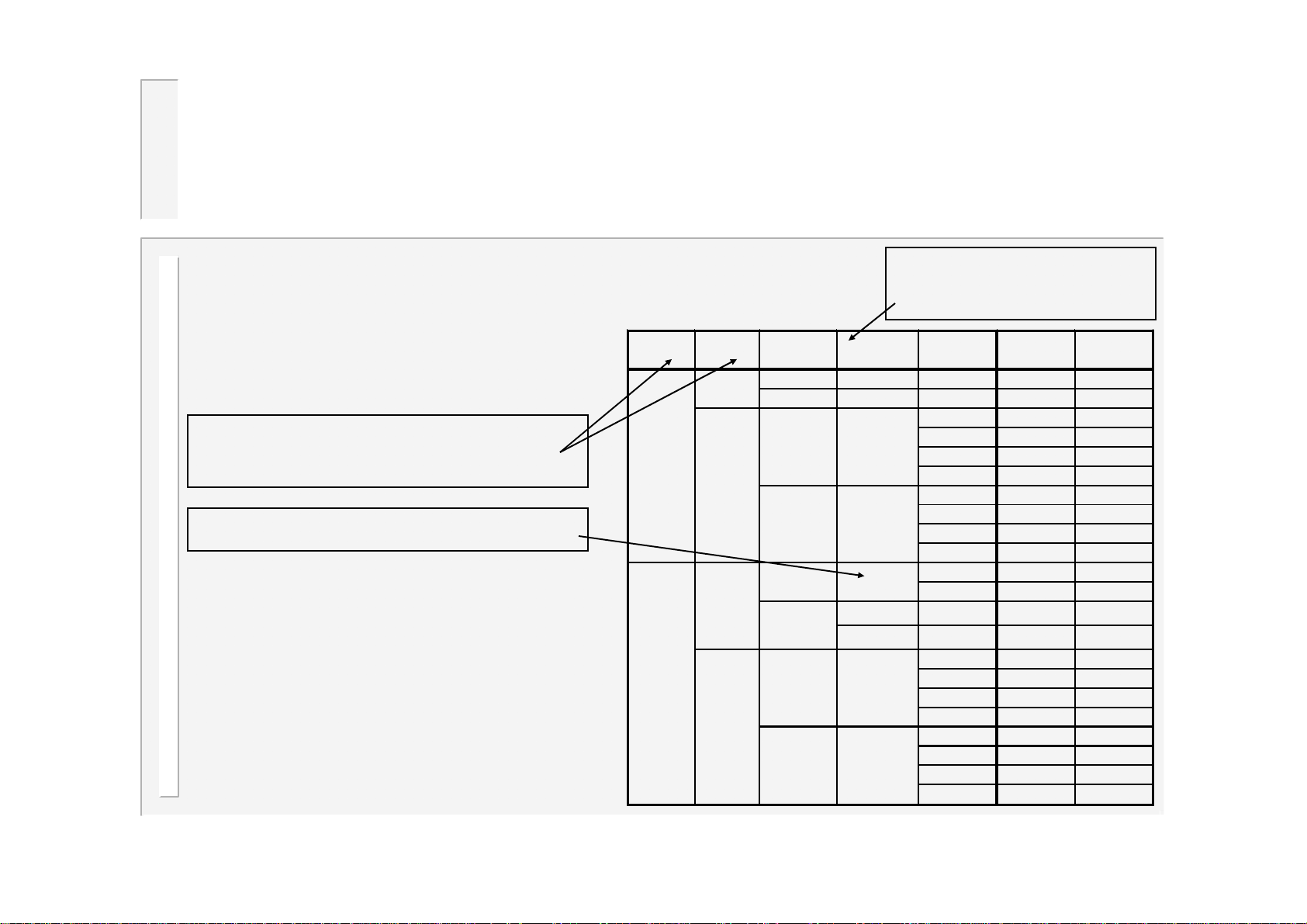
Program selection
Single/
Bi
U
Ext
START
P
Programmes can be selected in a variety of
different ways, depending on the settings
used.
Note: If 2-input binary is selected, then the
inputs START 1 and 2nd STAGE must be
activated within 0.3 s of each other.
Set these parameters in the
configuration file.
X = don’t care, or not connected
Note that if a program number exceeds the
maximum (63), then the number will wrap around
through 0.
e.g.
If N=62, then N+3=65. Applying wrap-around,
N=N-64, giving a final value of N=1.
Dual
Single
Dual
Binary
1of4
Binary
1of4
nary/
1of4
Set this parameter
from the main menu
se
program
N = 0..63 X 1 N 1
EXT P=0..63 1 P 1
N = 0..15
EXT
N = 0..31
EXT
N = 0..15
EXT
ernal
selection
X
X
X
P
=0..7
1
P
=0..7
2
X
X
rogram
input
1N 1
3N+16 1
2N+32 1
4N+48 1
10 1
316 1
232 1
448 1
1N 1
2N+32 2
1
2
1N 1
3N+16 1
2N+32 2
4N+48 2
10 1
316 1
232 2
448 2
selected Gun
P
1
P2+32
1
2
68
WS2003 V1.69
Page 69
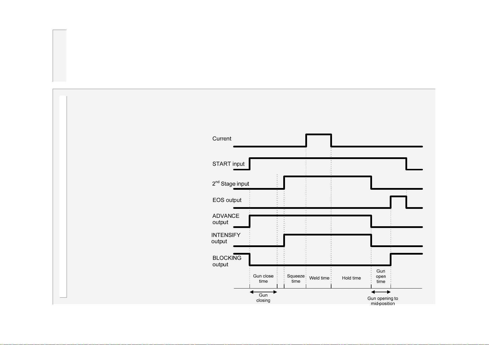
OHMA (Air over Oil) system
The OHMA system uses three valves to control the opening and closing of the
electrodes. If Retract is used, the timing of the valve operations is used to control
the gap between the electrodes in their mid-position. To enable the OHMA system,
you must make appropriate settings in the configuration file.
Weld Stroke
When a Start input is given to the weld
control the Blocking valve is switched
off and the Advance valve is switched
on. This closes the electrodes onto the
work-piece. At the end of the ‘Gun
close’ time, the 2ndstage input and/or
‘wait for pressure’ function is/are
checked, before the Intensify valve
switches on to provide the electrode
force required for welding.
The weld sequence proceeds in the
usual way until the end of the Hold time
when the Advance and Intensify valves
switch off. The electrodes then start to
open until the Blocking valve switches
on and prevents further opening. The
timing of the Blocking valve turning on
(the Gun Open Time) sets the position
to which the electrodes open. The End
of Sequence output operates when the
Blocking Valve switches on.
69
WS2003 V1.69
Page 70
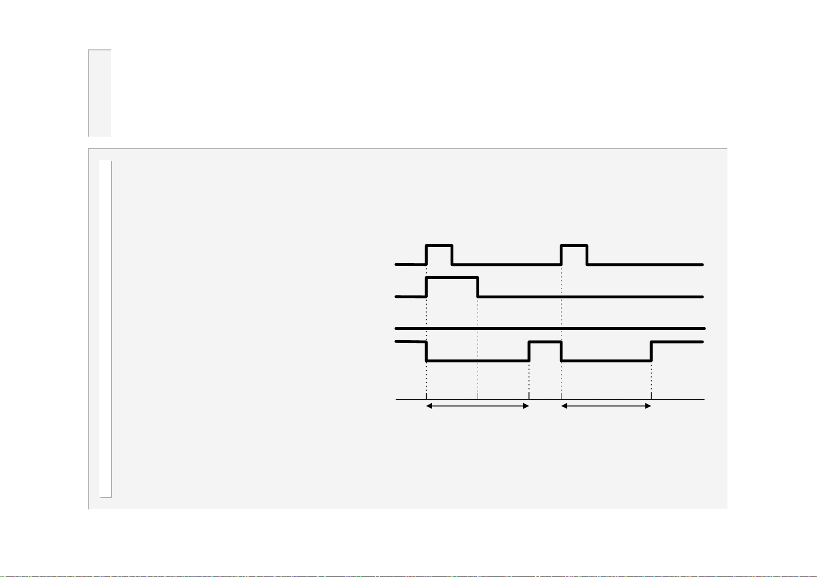
…OHMA system
Retract Stroke
With the electrodes in the fully open position the control will not begin a weld sequence. A Retract input is
required to move the electrodes to their mid-position.
When a Retract input is given, the
Blocking valve is switched off and the
Advance valve is switched on. This
starts the electrodes moving towards
their mid-position. After the Retract
Close time the Advance valve is
switched off. The Retract Close Delay
time then begins and when complete,
the Blocking valve is switched on,
halting the movement of the electrodes.
Hence, these times control the mid
position of the electrodes. In this
condition the timer is ready to weld.
When in this “ready” condition, if a
Retract input is detected, the Blocking
valve is switched off for the duration of
the Retract Open time. This allows the
electrodes to move to the full open
position.
RETRACT
input
ADVANCE
output
INTENSIFY
output
BLOCKING
output
Retract close
time
Gun closing to mid-position
Retract delay
time
Retract open time
Gun fully opening from
mid-position
70
WS2003 V1.69
Page 71
Disabling edits
Normally, a user can access the
parameters via the keypad on the
WSP3 programming pendant, and
make any changes, as required.
Under some circumstances, it may be
desirable to prevent such general
access.
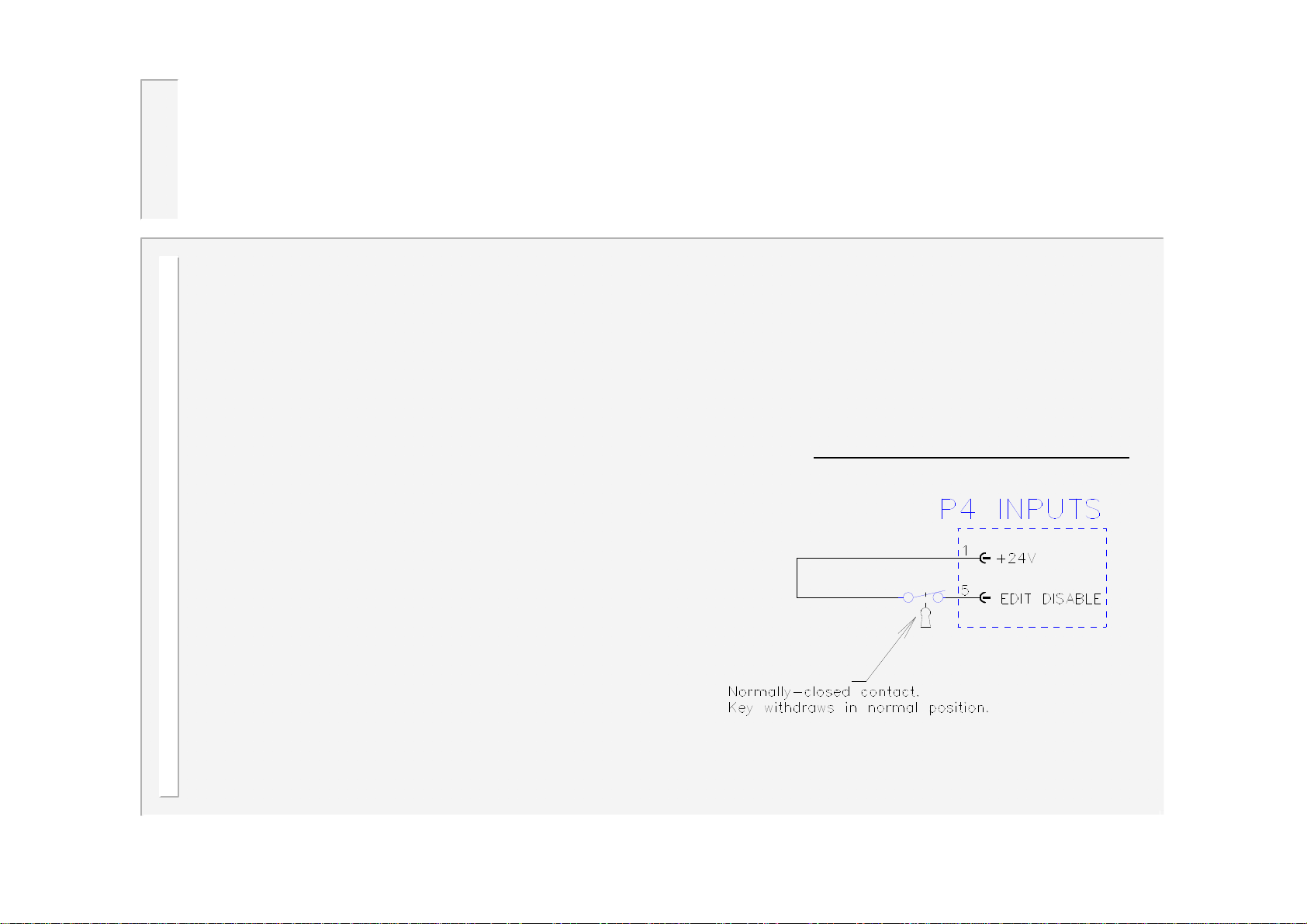
The timer provides an input called
‘EDIT DISABLE’, which can be used
to block all parameter edits. With this
input on, it will still be possible to view
parameters, but no changes are
permitted via the keypad.
If edits are attempted, the display will
briefly show
It is suggested that this input is
controlled via a key-switch, such
that only the key-holder is able to
open the switch, and thus be able
to edit parameters.
Typical connections to Timer
** EDITS DISABLED **
and the edit will be blocked.
If this feature is not required, simply
leave this input unconnected.
71
WS2003 V1.69
Page 72
Pop-up current meter
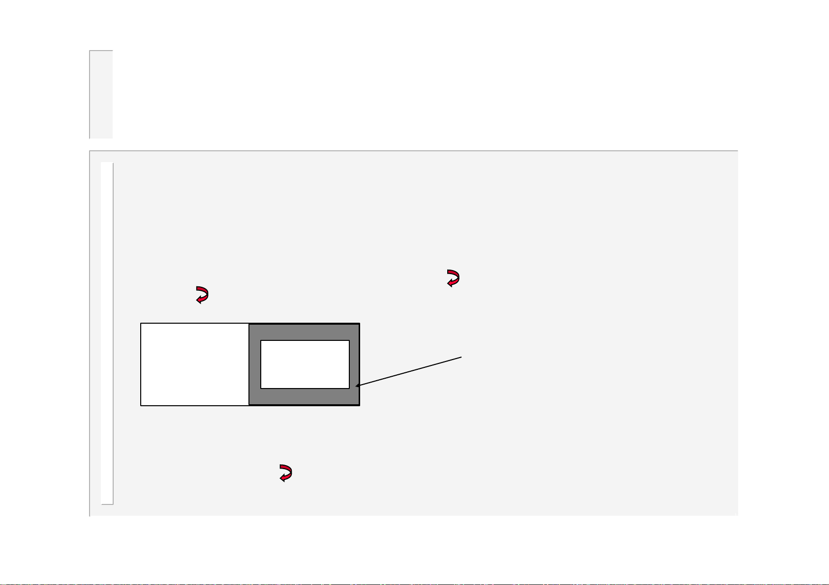
The timer will measure the current on both the weld1 and weld 2 intervals, and this is
displayed on the diagnostic screen.
Often, when programming the timer, you will need to refer to these current
measurements. In order to avoid having to switch between screens, there is a
convenient pop-up current meter window, which allows you to view the measured
currents without leaving the screen you are on.
The pop-up meter is activated by pressing the key. To close the pop-up window,
press the key again.
<<< CALIBRATION >>>
TOROID: 150 mV/kA
TOROID FACTOR x1
S/P RATIO 50:1
Note that the window may not show both weld1 and weld2, if either interval was not
used.
Some screens use the key for another purpose (such as selecting an item from a
list). In this case, the pop-up meter is not available from that screen.
I1=6.06kA
I2=8.45kA
Pop-up window
72
WS2003 V1.69
Page 73
Replacing a WS2000 timer
If you have an existing installation with a WS2000 timer and a primary toroid, and you
are replacing that timer with a WS2003, then use the following procedure:
1. Note the existing settings (weld program), measure the welding current with a meter, and note the
current measured by the WS2000.
2. Fit the new timer (WS2003).
3. Adjust the primary toroid calibration trimmer to fully anti-clockwise.
4. Initialise the data in the WS2003.
5. Set the toroid sensitivity to 1400mV/kA
6. Set up the appropriate welding program, using the settings recorded in step 1, but using PHA mode.
7. Weld – measure the current (x) with a meter, and (y) on the timer.
8. Calculate x/y and enter this as the S/P ratio.
9. Weld – the current (z) on the timer should agree with the meter.
10. Enter z (the current value) into the current parameter in the timer program.
11. Weld.
12. Select CCR if required.
73
WS2003 V1.69
Page 74
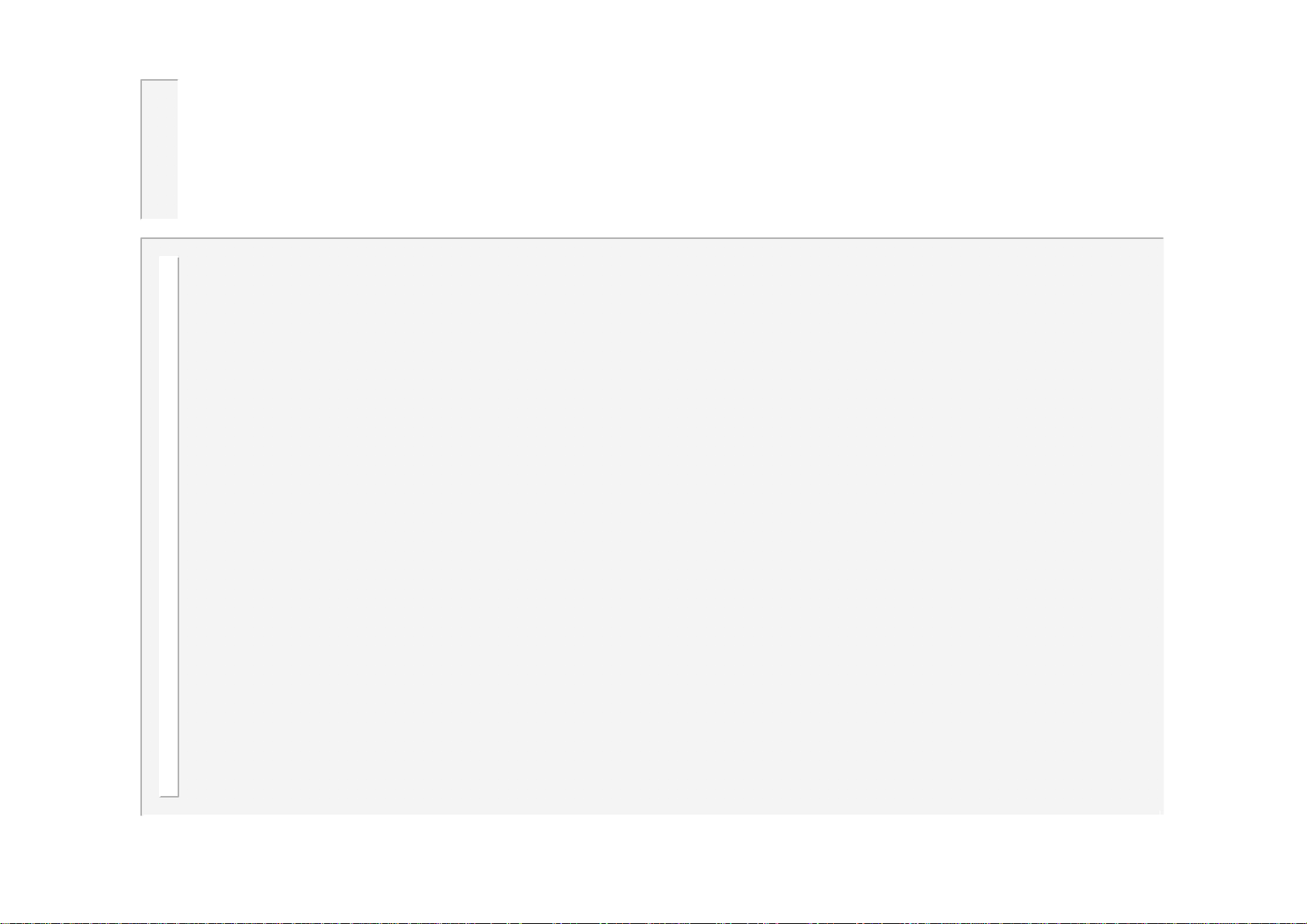
Operation: basic spot weld – no weld faults
Current
START input
EOS output
FAULT output
WAV output
SQZ
W2
W1=0, C1=0, Pulses=1, OFF=0
74
HLD
WS2003 V1.69
Page 75
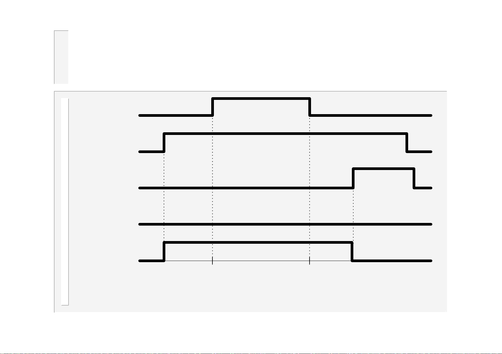
Operation: basic spot weld – weld fault
Current
START input
EOS output
FAULT output
WAV output
SQZ
W2
W1=0, C1=0, Pulses=1, OFF=0
75
HLD
WS2003 V1.69
Page 76
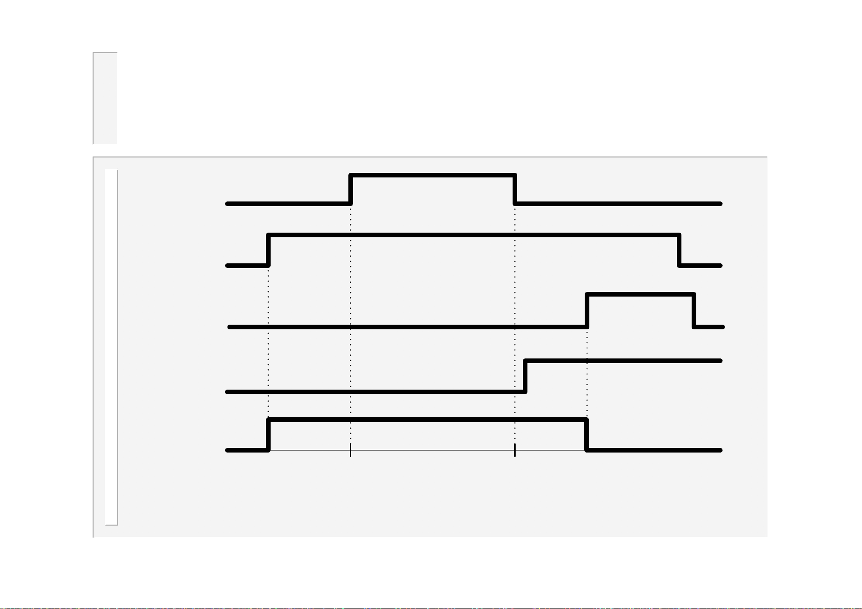
Operation: repeat spot weld
Current
START input
WAV output
PSQ
SQZ
W2
HLD
W1=0, C1=0, C2=0, Pulses=1
OFF
SQZ
76
W2
HLD
OFF
SQZ
W2
HLD
WS2003 V1.69
Page 77
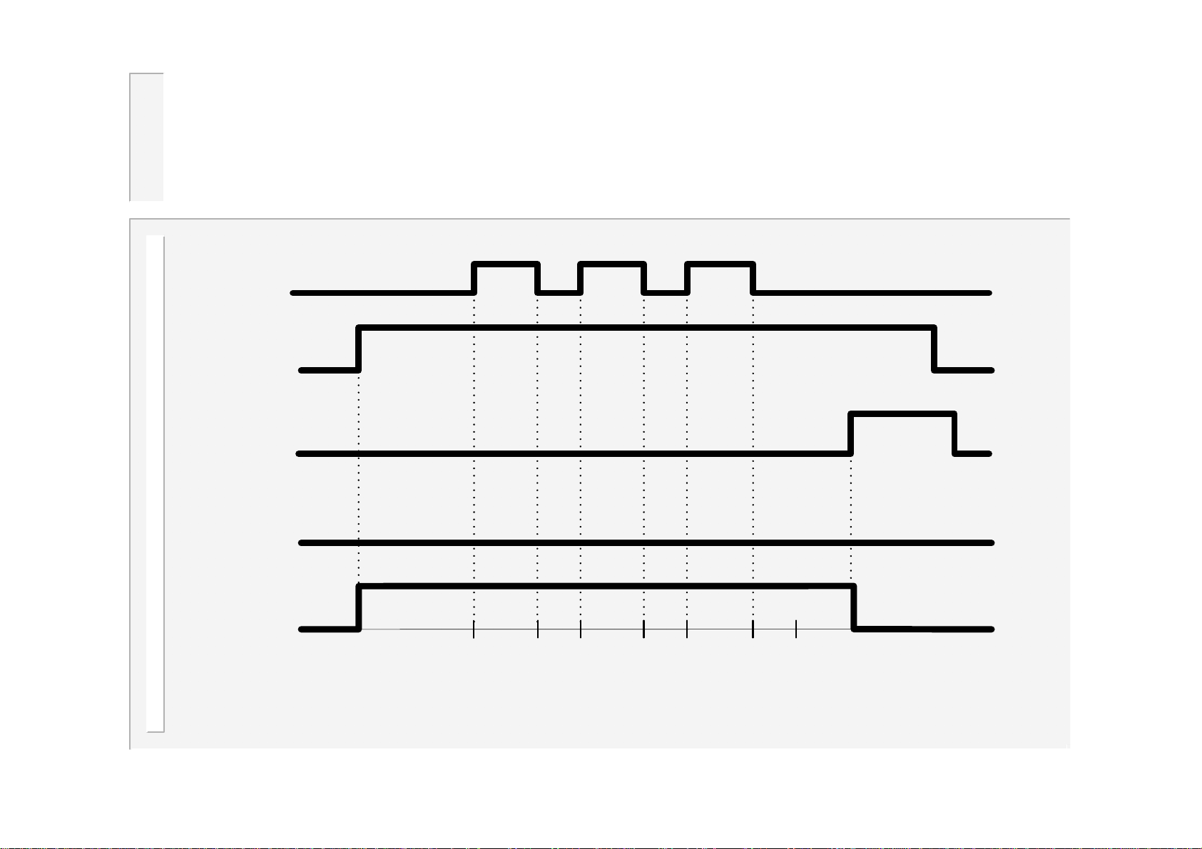
Operation: pulsation spot weld
Current
START input
EOS output
FAULT output
WAV output
C2
SQZ
W2
W1=0, C1=0, Pulses=3, OFF=0
W2
C2
77
W2
C2
HLD
WS2003 V1.69
Page 78
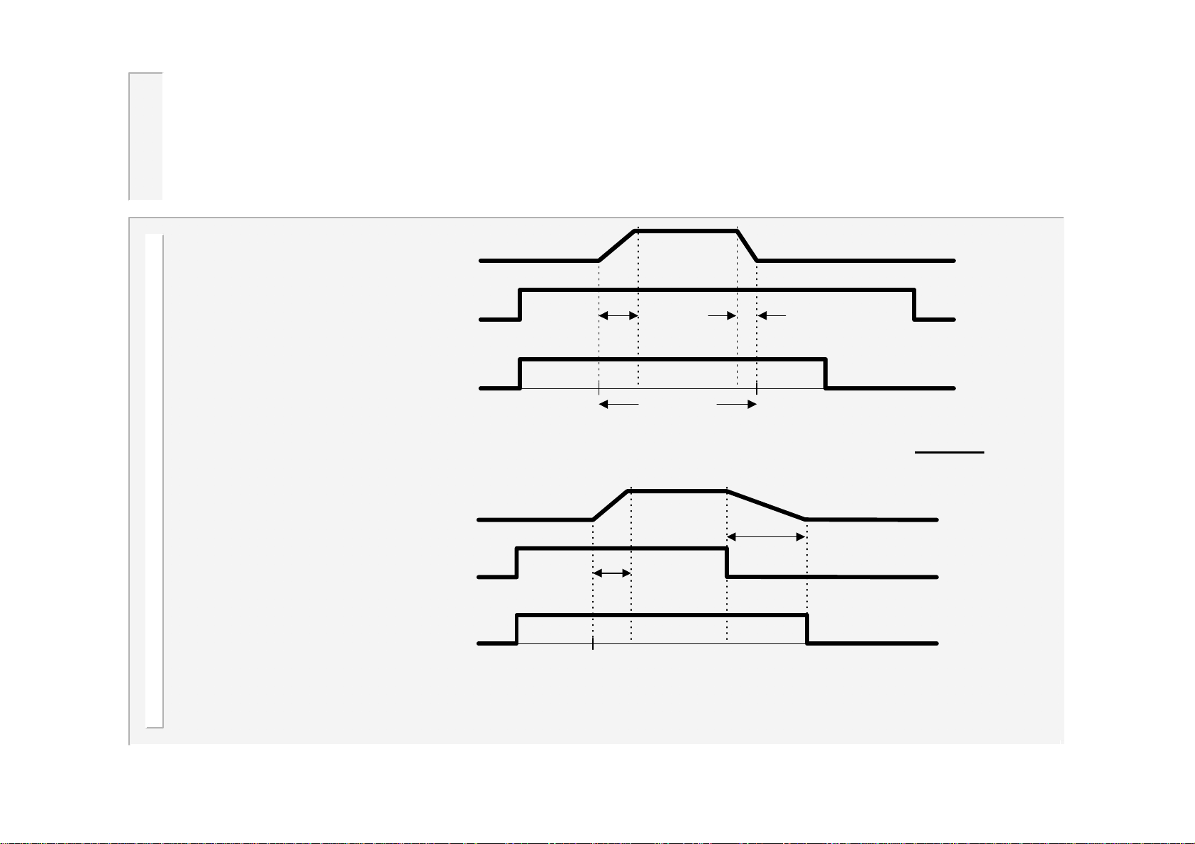
Operation: Upslope and Downslope
Current
START input
Spot
WAV output
The upslope and downslope times are part of the overall weld time – they do not add
to the weld time.
Current
Upslope time Downslope time
Weld time
Downslope time
Seam
START input
Upslope time
WAV output
Note that for seam welds, the downslope time begins when the initiation input turns
off.
78
WS2003 V1.69
Page 79
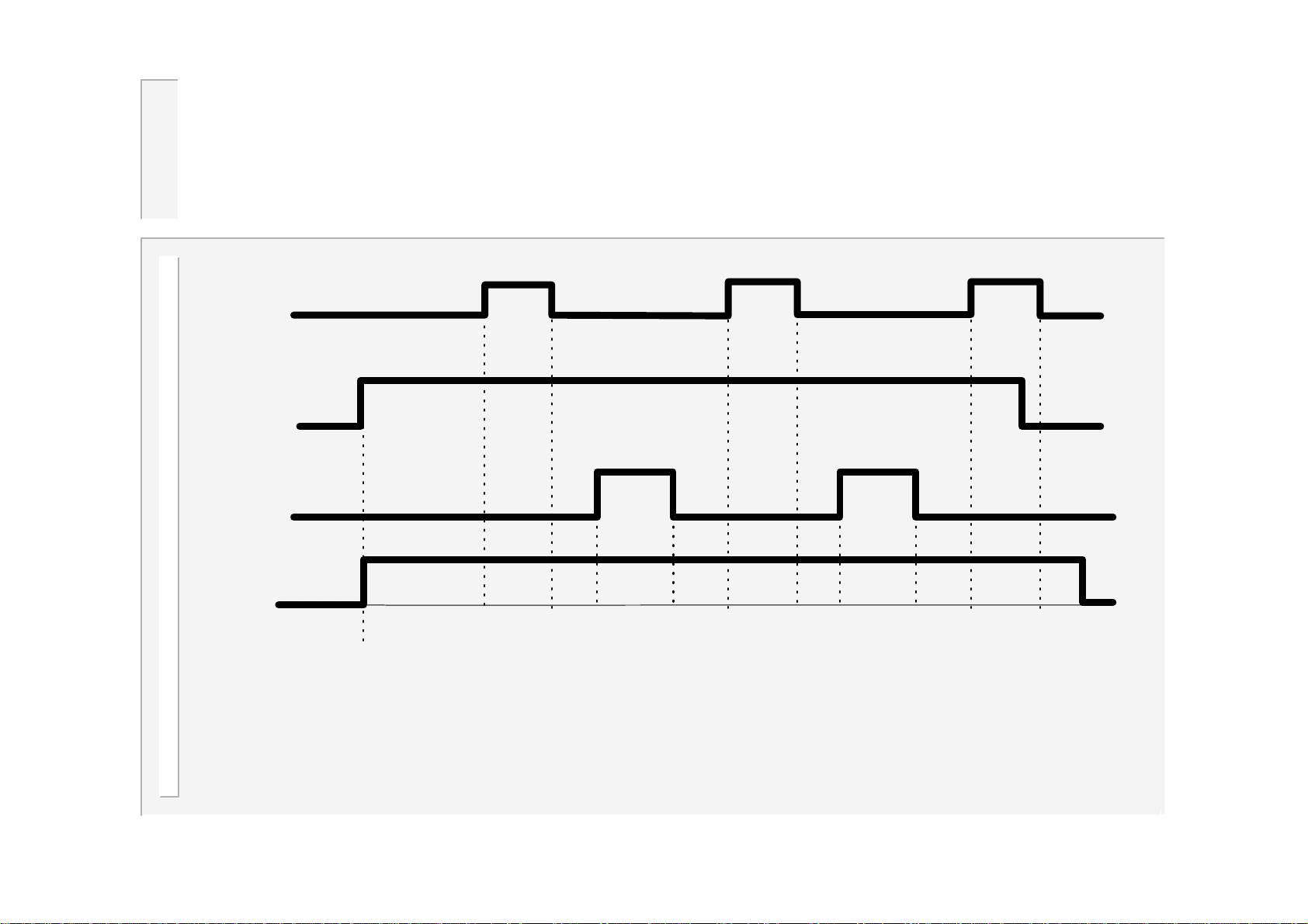
Operation: roll-spot welding
Current
START input
MOTOR output
WAV output
PSQ
SQZ
W2
W1=0, C1=0, C2=0, Pulses=1
HLD
OFF
SQZ
79
W2
HLD
OFF
SQZ
W2
HLD
WS2003 V1.69
Page 80
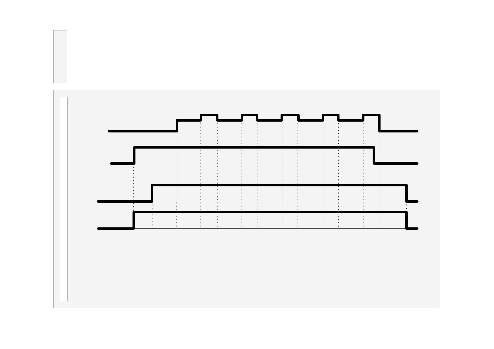
Operation: seam welding (dual heat)
Current
START input
MOTOR output
WAV output
PSQ
SQZ
W1
W2
C1=0, C2=0
W1
W2
W1
80
W2
W1
W2
W1
W2
HLD
WS2003 V1.69
Page 81
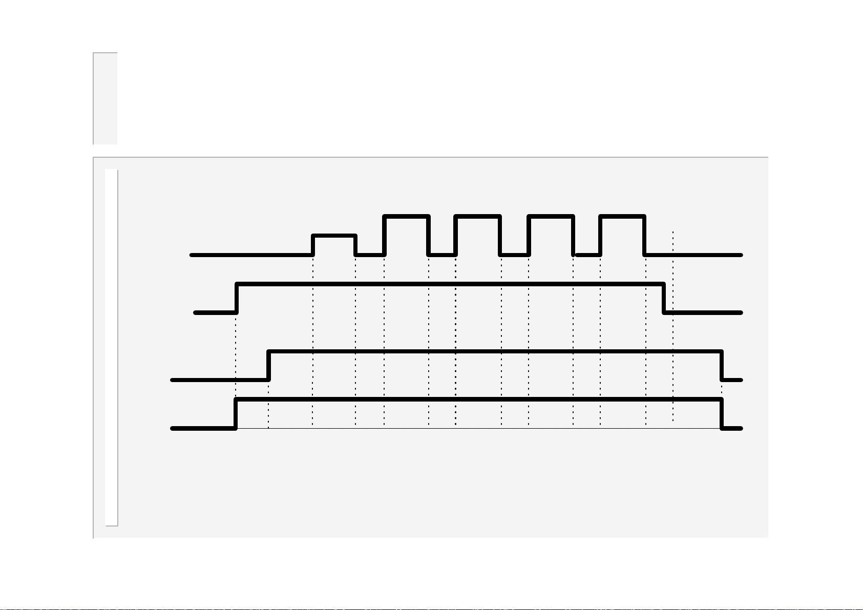
Operation: seam welding (pre-heat)
Current
START input
MOTOR output
WAV output
PSQ
SQZ
W1
C1
W2
C2
W2
81
C2
W2
C2
W2
C2
HLD
WS2003 V1.69
Page 82
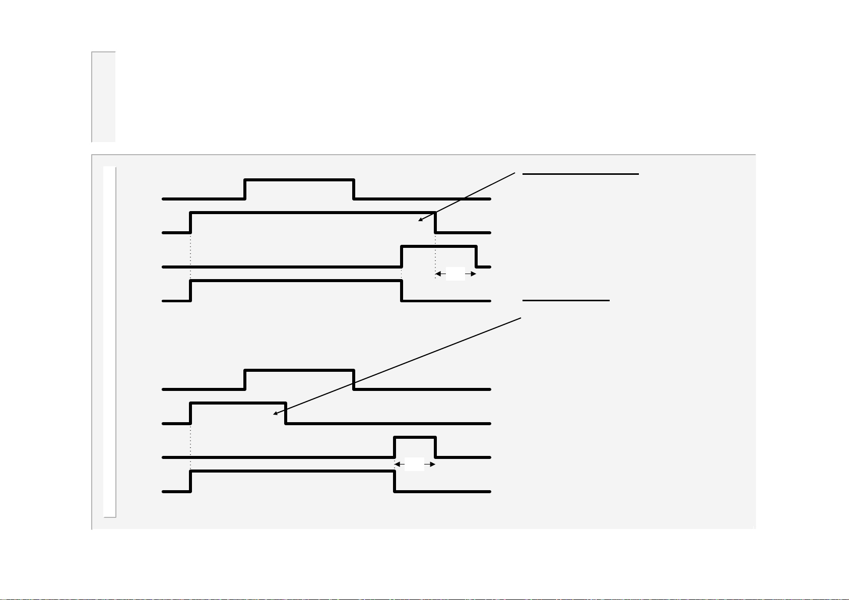
Operation: EOS signal
Handshake mode: The start signal
Current
START input
EOS output
20~
WAV output
Current
START input
EOS output
20~
WAV output
remains on until EOS is given. When
start is removed, EOS goes off
immediately (cancel with start mode)
or after 20 cycles (fixed pulse mode).
This is the recommended method of
operation for automatic systems.
Pulsed mode
off before the end of the hold time.
The EOS signal is a fixed pulse of 20
cycles.
If a new start signal is given during
the EOS pulse, a new sequence will
start immediately. Then EOS will go
off immediately (cancel with start
mode) or at the end of the 20 cycle
pulse (fixed pulse mode).
: The start signal goes
82
WS2003 V1.69
Page 83
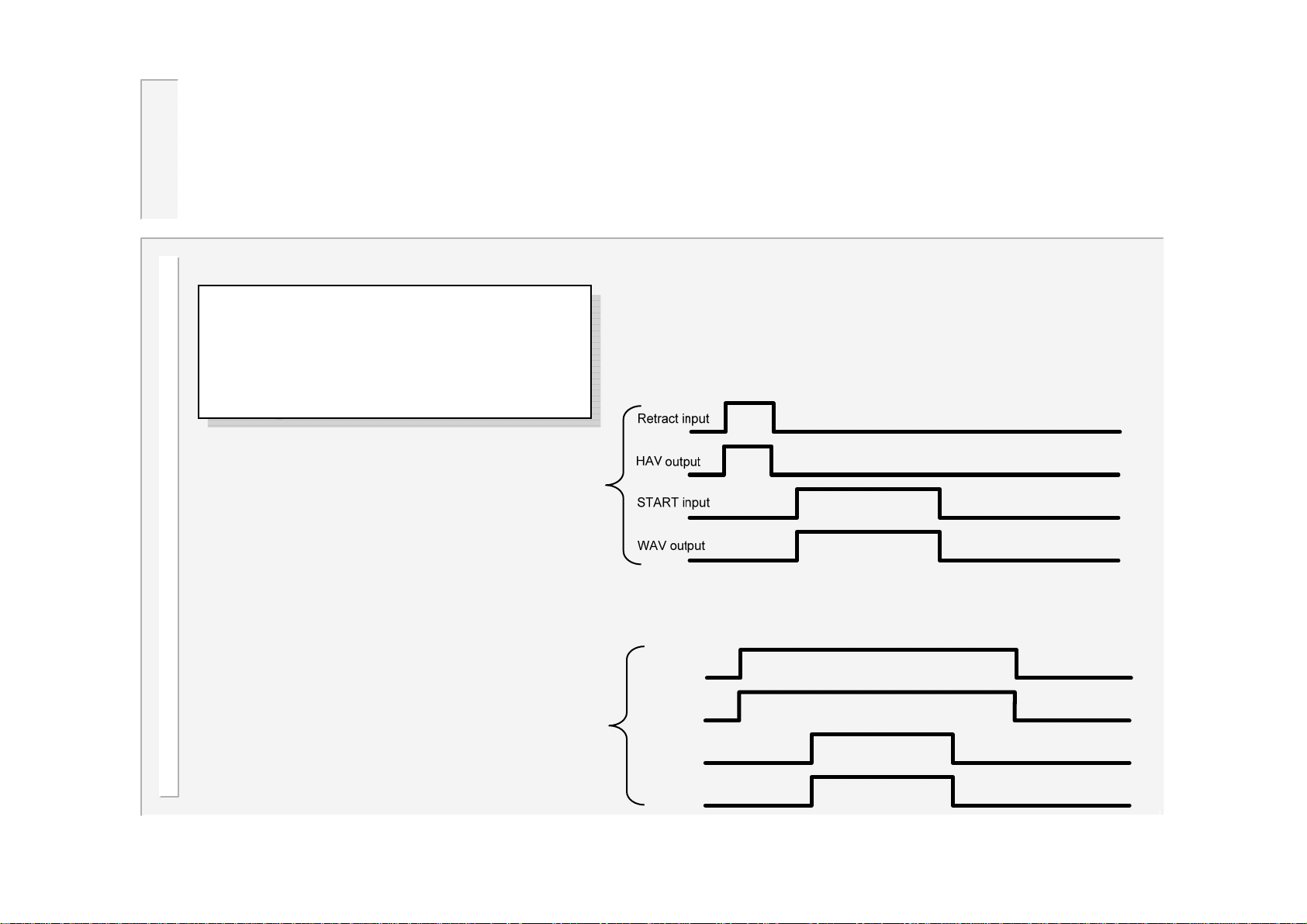
Operation: Retract
The retract operating mode
The retract operating mode
(Simple/Hi-lift+/Hi-lift-
(Simple/Hi-lift+/Hi-lift-
/Maintained) is set in the
/Maintained) is set in the
configuration file.
configuration file.
No/ Simple
Maintained
Retract input
HAV output
START input
WAV output
83
WS2003 V1.69
Page 84
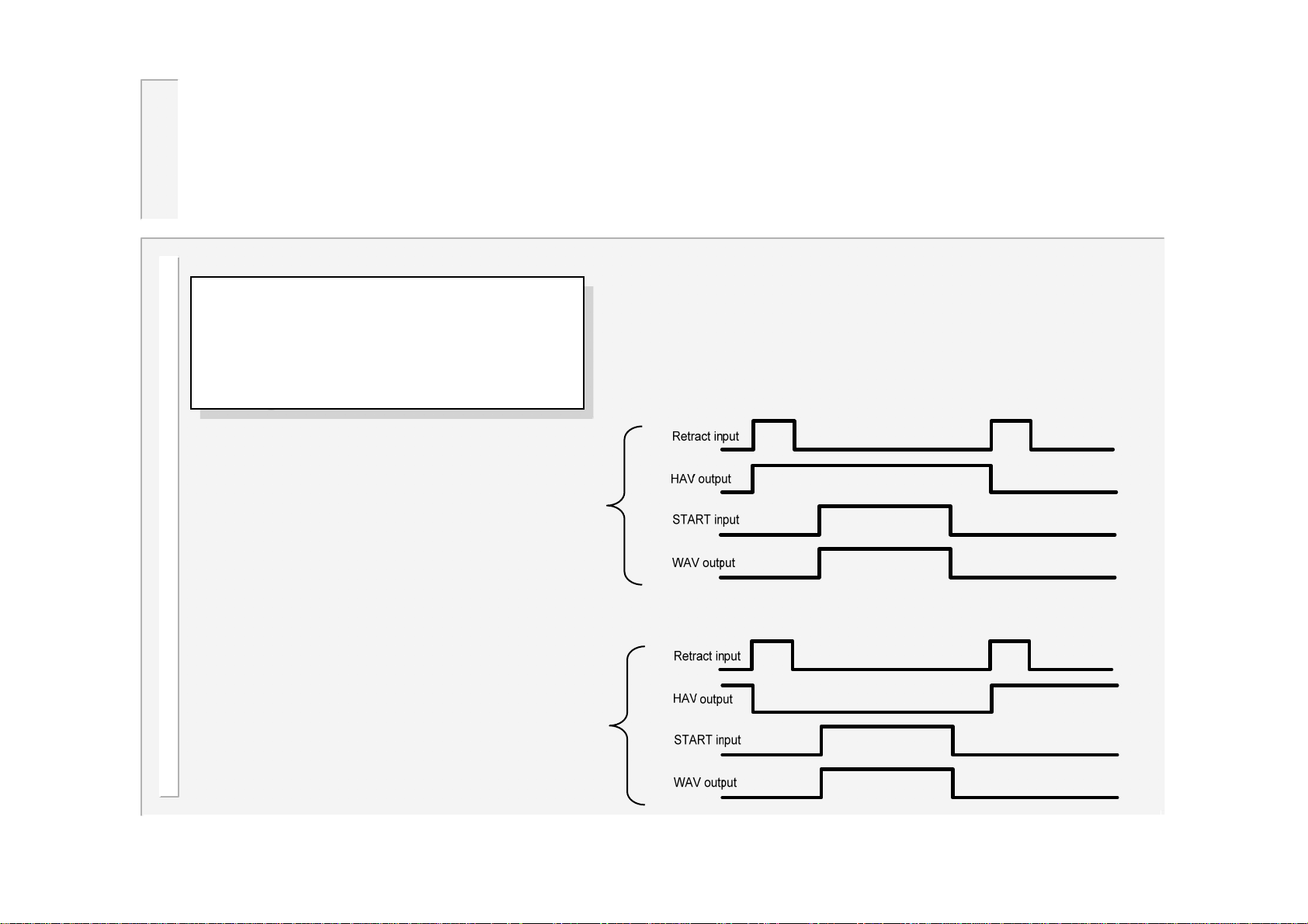
Operation: Hi-lift
The retract operating mode
The retract operating mode
(Simple/Hi-lift+/Hi-lift-
(Simple/Hi-lift+/Hi-lift-
/Maintained) is set in the
/Maintained) is set in the
configuration file.
configuration file.
Hi-lift+
Hi-lift-
84
WS2003 V1.69
Page 85
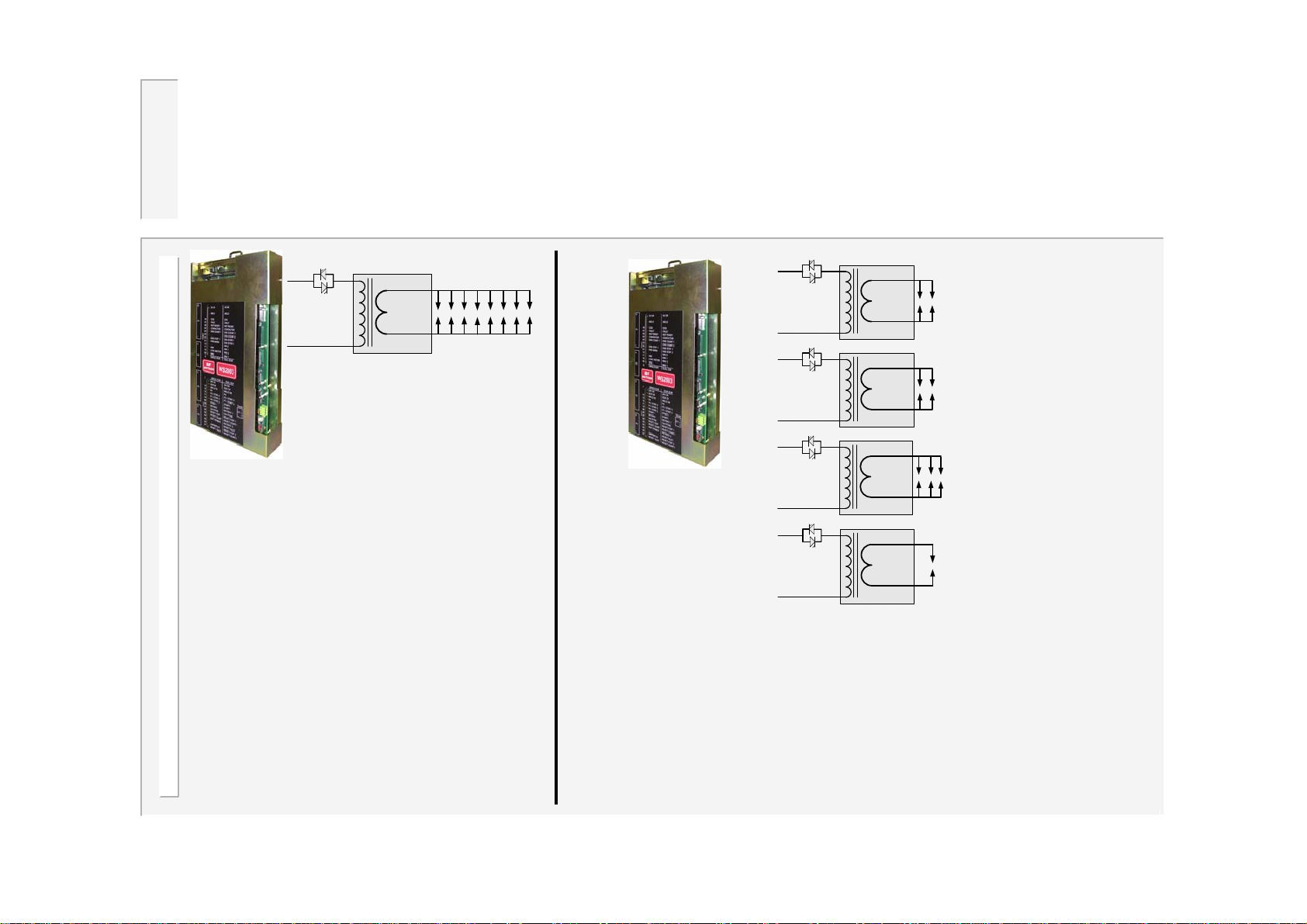
Multiwelding
SCR
Welding
transformer
Up to 16 pairs of
electrodes, distributed
randomly across the
welding transformers.
WS2003
configured for
single gun use.
Only one transformer/SCR is
connected. Electrodes must be
closed one pair at a time.
WS2003
configured for
multi-gun use.
Up to 16 welding transformers/SCRs when used
with BD16 decoder, otherwise up to 4 SCRs.
Up to 16/4 transformers/SCRs can be connected. Up to 16
electrode pairs can be closed at a time. Control can ripplefire through up to 16 spots, or each spot can be individually
triggered. Transformers/SCRs can be different sizes.
85
WS2003 V1.69
Page 86
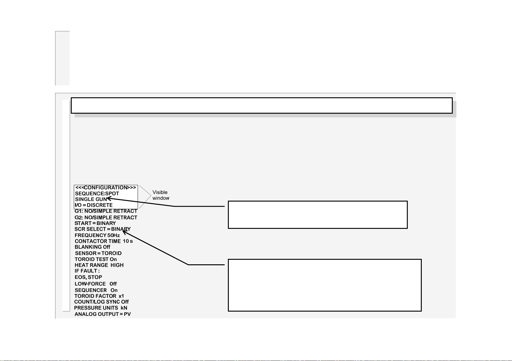
Configuring WS2003 for multiwelding
There are two modes available for multiwelding: ‘MULTI-GUN’ and ‘MULTI-GUN CASCAD E’.
There are two modes available for multiwelding: ‘MULTI-GUN’ and ‘MULTI-GUN CASCAD E’.
Multi-gun mode allows each welding program to be triggered independently, in the traditional way, but allows for
selection of a transformer and electrode.
In multi-gun cascade mode, up to sixteen welding programmes can be grouped together, and triggered from a
single start command. The programmes then ripple through with minimal time between them, selecting transformers
and electrodes on the fly. The group of programmes is referred to as a cascade.
Selection of these modes is made by selecting ‘EDIT CONFIGURATION’ from the config. Menu:
Operating mode selection: Press the + or – keys
until either multi-gun or multi-gun cascade is shown.
SCR select: use BINARY if the SCRs are equiped with a
decoder (such as a BD16), otherwise select 1 of 4.
Binary: up to 16 SCRs.
1 of 4: up to 4 SCRs
86
WS2003 V1.69
Page 87
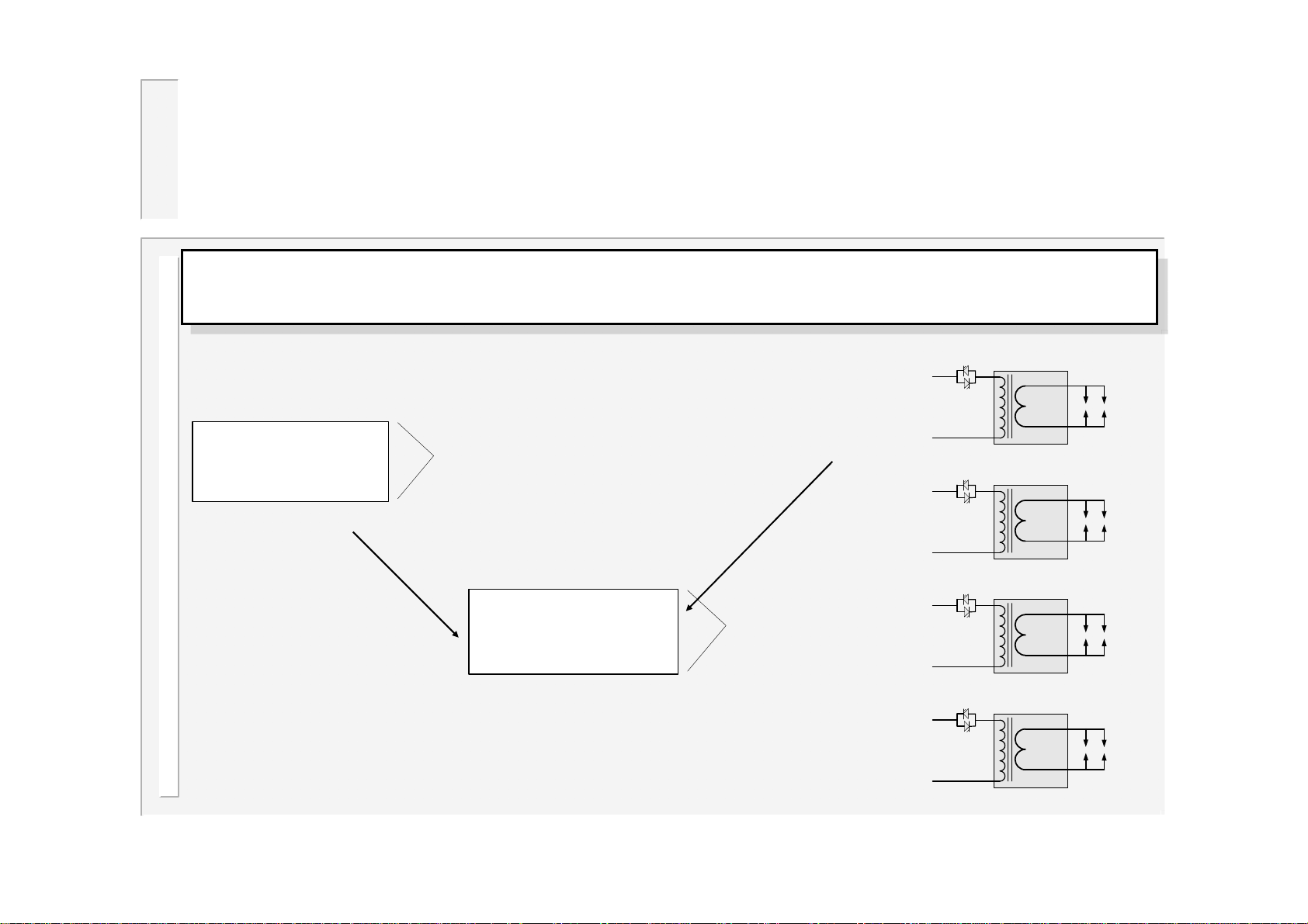
Electrode/Transformer
assignment
The physical arrangement of the electrodes and welding transformers must be
The physical arrangement of the electrodes and welding transformers must be
entered into the control.
entered into the control.
1. From the config. menu, select
‘EDIT TRANSFORMERS’.
<<< CONFIG. MENU>>>
EDIT CONFIGURATION
EDIT CALIBRATION
EDIT OUTPUT MAP
EDIT INPUT MAP
EDIT TRANSFORMERS
SET-UP ADAPTERS
BACKUP ALL DATA
RESTORE ALL DATA
INITIALISE ALL DATA
EDIT SYSTEM SETUP
3. Each transformer has a
separate calibration file.
Perform the calibration
procedure (see main manual)
for each transformer
connected.
Visible
window
In the example shown here:
Electrodes 1 and 2 are attached to Transformer 1.
Electrodes 3 and 4 are attached to Transformer 2.
Electrodes 5 and 6 are attached to Transformer 3.
Electrodes 7 and 8 are attached to Transformer 4.
Electrodes 9..16 are not used.
2. Assign each electrode
to a transformer.
<<<TRANSFORMERS>>>
E1 -> T1 E2 -> T1
E3 -> T2 E4 -> T2
E5 -> T3 E6 -> T3
E7 -> T4 E8 -> T4
E9 -> T9 E10 -> T10
E11 -> T11 E12 -> T12
E13 -> T13 E14 -> T14
E15 -> T15 E16 -> T16
Visible
window
T1
E1
E2
T2
E3
E4
T3
E5
E6
T4
E7
E8
87
WS2003 V1.69
Page 88
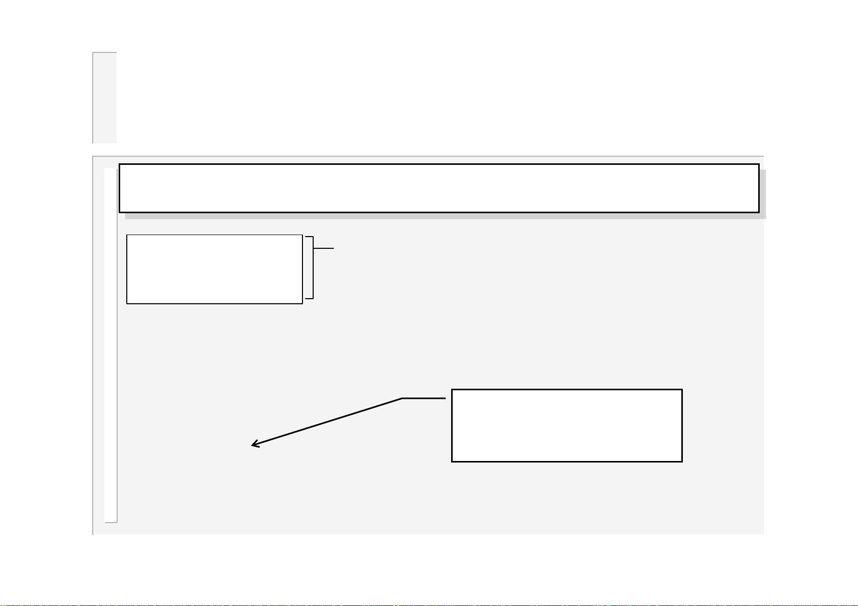
Assigning a weld program to an
electrode
Each weld program should be assigned to a particular electrode. This is done on the
Each weld program should be assigned to a particular electrode. This is done on the
‘EDIT PROGRAM’ screen, accessed from the main menu.
‘EDIT PROGRAM’ screen, accessed from the main menu.
<<< PROGRAM 0 >>>
I1=7.50kA 25.0% PHA
I2=10.0kA 50.0% CCR
[email protected]% NORM
PSQ= 0 SQZ= 10
W1 = 0 C1 = 0
W2 = 10 C2 = 0
Pulses(W2-C2) = 1
UPSLOPE = 3
DOWNSLOPE = 0
Visible
window
In the example shown here:
HOLD = 10
OFF = 0 (SINGLE)
ELECTRODE = 1
Whenever a program is run, the control will automatically trigger the correct transformer, by referencing the
electrode/transformer assignment table, as shown on the previous page. In addition, the electrode number is also
used to access the appropriate stepper, counter and calibration information.
Weld program 0 is assigned
to Electrode 1.
88
WS2003 V1.69
Page 89
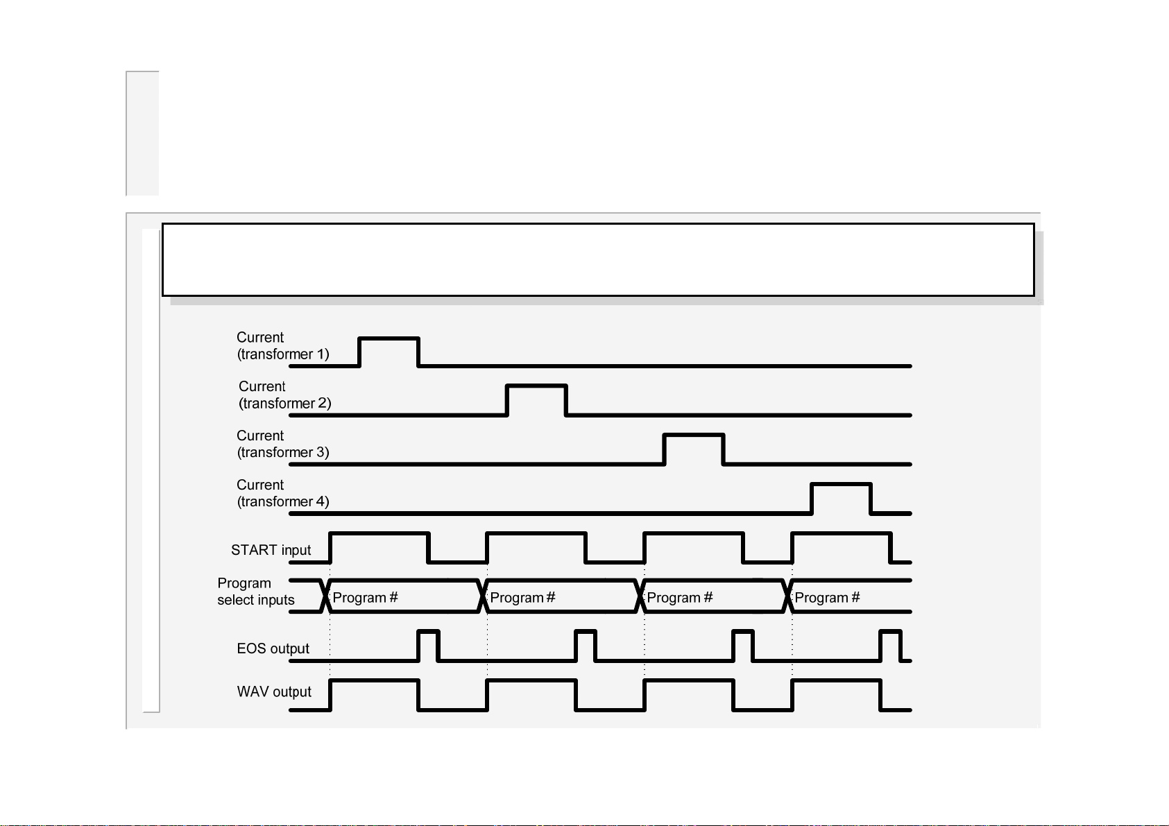
Multi-gun operation
Multi-gun mode allows each welding program to be triggered independently,
Multi-gun mode allows each welding program to be triggered independently,
in the traditional way, but allows for selection of a transformer and electrode.
in the traditional way, but allows for selection of a transformer and electrode.
89
WS2003 V1.69
Page 90
Multi-gun cascade operation
In multi-gun cascade mode, up to sixteen welding programmes can be grouped
In multi-gun cascade mode, up to sixteen welding programmes can be grouped
together, and triggered from a single start command. The programmes then ripple
together, and triggered from a single start command. The programmes then ripple
through with minimal time between them, selecting transformers and electrodes on the
through with minimal time between them, selecting transformers and electrodes on the
fly. The group of programmes is referred to as a cascade. Up to 16 cascades may be
fly. The group of programmes is referred to as a cascade. Up to 16 cascades may be
programmed.
programmed.
To set up a cascade, select ‘EDIT CASCADE’ from the main menu.
To set up a cascade, select ‘EDIT CASCADE’ from the main menu.
<<< CASCADE 0 >>>
STEPS = 5
S01:P00->E01->T01 ON
S02:P02->E02->T02 ON
S03:P10->E03->T03 ON
S04:P11->E04->T04 ON
S05:P12->E05->T05 ON
Note that in multi-gun cascade mode, the program selection inputs refer to a
cascade, and not directly to a weld program.
Visible
window
Individual steps
can be turned
ON or OFF to
assist setting up.
In the example shown here:
The cascade consists of 5 steps,
using programmes 0,2,10,11 and 12.
Note that the electrode and
transformer numbers are
automatically assigned, by reference
to the electrode number in the
selected weld program.
90
WS2003 V1.69
Page 91
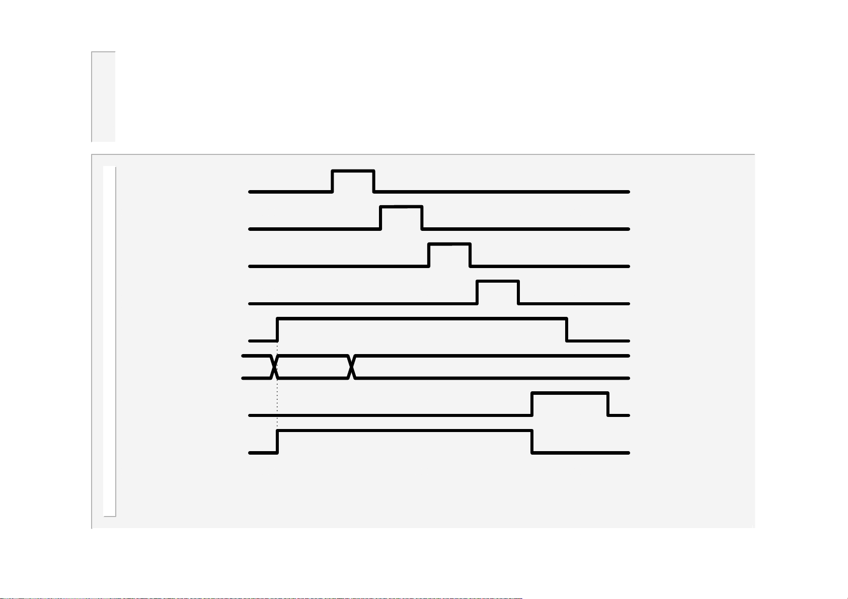
…multi-gun cascade operation
Curren t (transformer 1)
Curren t (transformer 2)
Curren t (transformer 3)
Curren t (transformer 4)
START input
Program
select inputs
Cascade #
EOS output
WAV output
91
WS2003 V1.69
Page 92
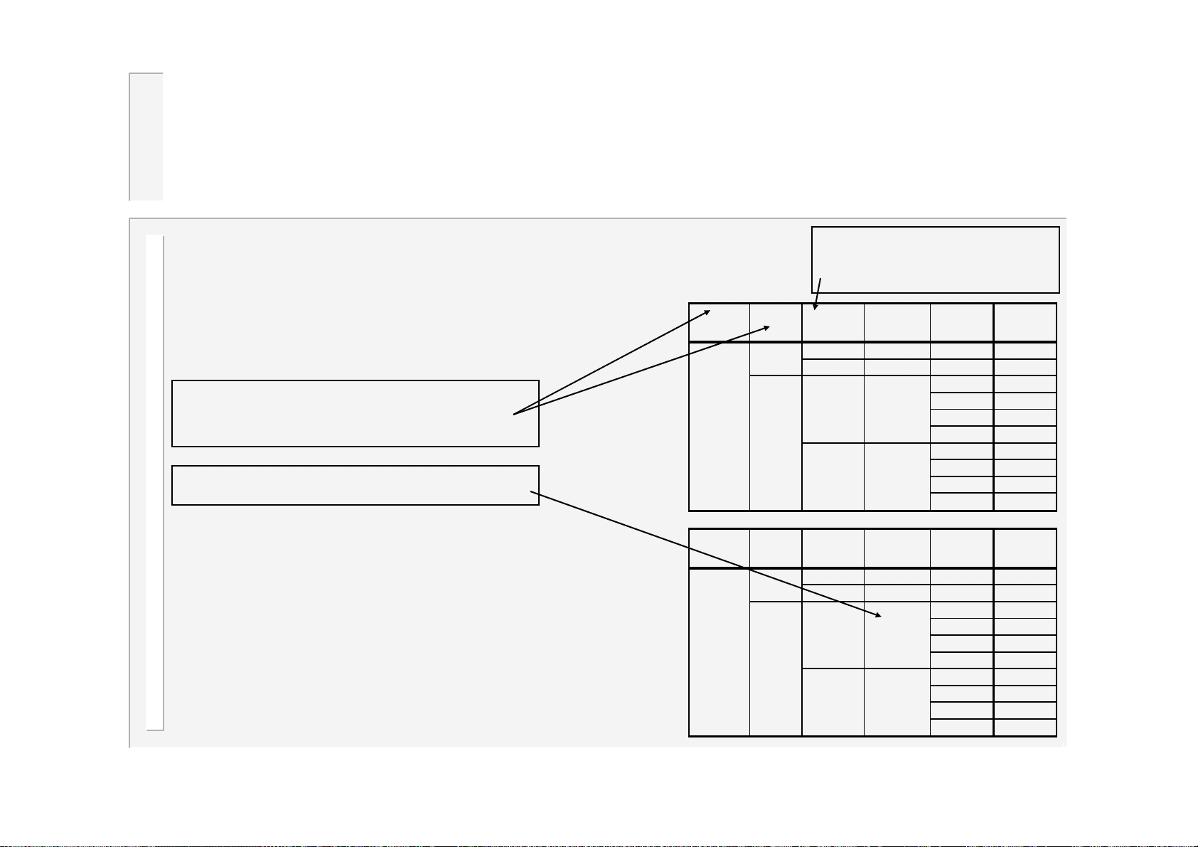
Program selection (multiweld)
Programmes can be selected
in a variety of different ways,
depending on the settings
used.
Set these parameters in the
configuration file.
X = don’t care, or not connected
Note that if a program number
exceeds the maximum (63 or 15),
then the number will wrap around
through 0.
e.g.
If N=62, then N+3=65. Applying
wrap-around, N=N-64, giving a final
value of N=1.
Mode
Multi-gun
Mode
Multi-gun
cascade
Binary/
1of4
Binary
1of4
Binary/
1of4
Binary
1of4
Set this parameter
from the main menu
Use
program
N = 0..63 X 1 N
EXT P=0..63 1 P
N = 0..15
EXT
Use
cascade
N = 0..15 X
EXT P=0..15
N = 0..3
EXT
External
selection
X
X
External
selection
X
X
START
input
1N
3N+16
2N+32
4N+48
10
316
232
448
START
input
1N
1P
1N
3N+4
2N+8
4N+12
10
34
28
412
Program
selected
Cascade
selected
92
WS2003 V1.69
Page 93
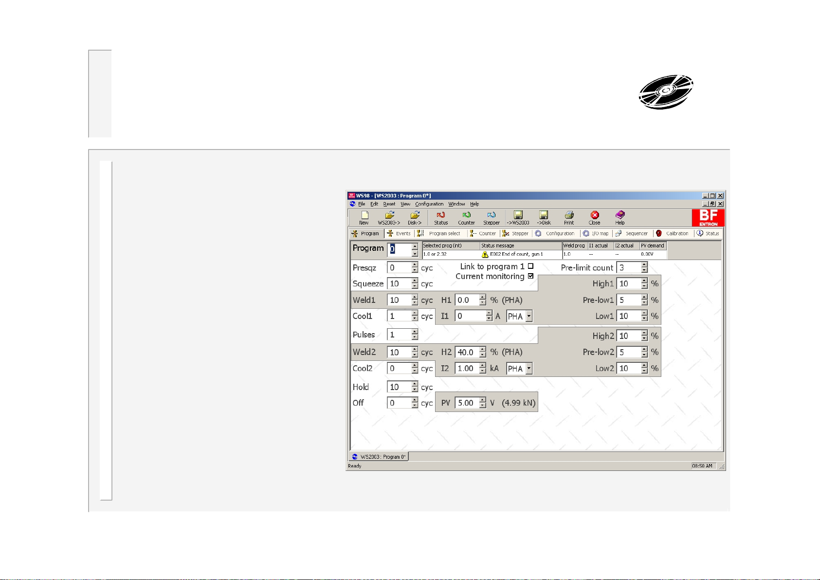
WS98-2003 PC software
WS98-2003 PC software is
available for use with the
WS2003 timer. This offers the
user the ability to program and
monitor the welding control,
and to back-up all of the
programmed data on a PC.
Timers may be connected to
the PC via RS232 (1 timer only)
or via Ethernet (multiple timers
on a network).
WS98-2003 is available on
CDROM, and works with all
versions of Microsoft
Windows™ (98 onwards).
Contact BF Entron for more
details.
93
WS2003 V1.69
 Loading...