

Page 1

Thank you for your selection of BFDX radio, We believe, the radio will provide convenient and reliable
communication and make your communication with high efficiency.
BFDX adopt the advanced technology and is convinced that the product quality and function will make
you feel satisfied.
BF-P118:Digital series radio in UHF
User Instructions
Transmitting operation is not allowed for the unlicensed radio within the government controlled area
The radio user should apply frequency license from local Radio Management Committee, illegal
operation will be subject to a fine or detention.
The repair can be performed only by the professional and technical personnel.
Safety
It is very important for the users to have the general knowledge and understanding of the risk involved
during using.
Warning
Explosive environment (gas, dust and smoke, etc) is not allowed
Please turn off the radio when in the in gas station or fuel pipelining
Guidelines for user
Please obey the following precautions to prevent fire, personal injury and radio damage,
●The best work way recommended is that transmitting for one minute and receiving for four minutes,
Long time continuously transmitting will battery pack heat, do not make the heated battery pack
contact with the plastic surface to avoid risk of the plastic surface been dissolved
●Never modify this radio in any case.
●Don't expose the radio to long periods of direct sunlight, nor place it close to heating appliances.
●Don’t place radio in excessively dusty, humid and wet area, also not unstable surface.
●If an abnormal smell or smoke is detected coming from the radio, switch off the power immediately
and remove the optional battery pack from the radio, contact your local dealer.
Contents
Unpacking and accessories checking
Battery information
Use the Li-ion battery pack
The characteristic of the Li-ion battery
Charging for the Li-ion battery
Accessory install
Install & Take off the battery pack
Install the antenna
Install the belt clip
Install the hand strap
1
Page 2

Getting acquainted
Operation Basics
Switching power ON/OFF
Adjusting the volume
Channel knob
Transmitting
Receiving
Emergency Alarm Indication
Radio features
General Settings
Tone alerts
Menu
Contact List
Radio mark explanation
Scan
Call log
Setting
Signaling system
Button function
Keypad
Configuring One Touch Calls
Text Message
Emergency Systems
Alarm Type
Mode
Impolite Retries
Polite Retries
Hot Mic Duration (sec)
Menu operation
Contact list
Channel
Scan Function
Scan
Scan group function
P118 Technical parameters
Unpacking and accessories checking
Note: The following explain for unpacking is aim to the dealer, promised service institution or
factory.
Please carefully unpack the radio, we recommend you identify the items listed in the following table. If
2
Page 3
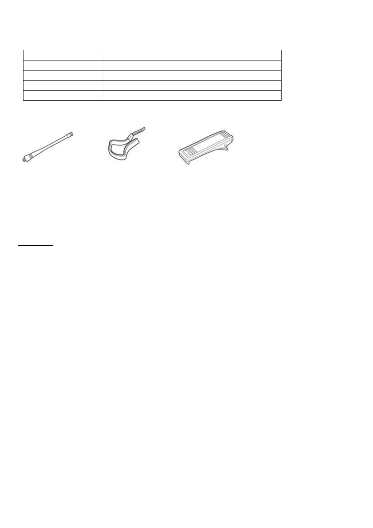
any item is missing or have been damaged, please immediately contact your dealer.
Supplied accessories:
Item No. Quantity
Antenna 1
Hand strap 1
Belt clip 1
User’s manual 1
Antenna Hand strap Belt clip
Alarm
●Please don’t charging too long for the battery pack
If the charging not finished in the stated time, please stop it, the battery pack may over heat and
smoking blast or build a fire.
●Please don’t put the battery pack into the microwave or high voltage container
The battery pack may over heat and smoking blast or build a fire.
●Please don’t close the damaged battery pack to the fire
If the battery pack broken and with the bad smell, please put them far from the flammable area. The
electrolyte is easy to fire, may result in the battery pack smoking or fire.
●Please don’t use the exceptional battery pack
If the battery pack smelled bad, different color, anamorphic or some other reason for the abnormity,
please take off the battery pack from the charger or operation equipment and not to use.
●Please use the special charger
The charger has been specifically developed for BF-P118, it is scientific and more safe for charging to
this model.
Use the Li-ion battery pack
●Please make it full charged before using
●In order to avoid the discharge, please take off the battery pack and placed it at cool and dry place
●When need long time to store the battery pack, please:
◆Tack off the battery pack from the radio
3
Page 4
◆If possible, please discharge for the battery pack
◆Put the battery pack on the cool (≤25) and dry pl℃ ace
The characteristic of the Li-ion battery
●The capacity reduce after charging and discharging again and again
●Even if not use the battery pack, it will also aging
●It need more time in wet environment for charging
●It may reduce the using life if charging in heat environment, the battery pack may aging faster when
store in heat environment. Please don’t leave the battery pack in vehicle or beside the heater.
●Please change the battery pack if the use duration become shorter even if it’s at the full capacity, Go
on charging and discharge for the battery pack, it may result in the electrolyte leak.
Charging for the Li-ion battery
When connect the charger of model BF-P118 to power supply, the light will turn green, put the battery
in then it will turn red and start to charging. The light will turn green after full, if the temperature exceed
the using range, the red light will flicker. If the battery damaged or undesirable circuit connect, the red
light will flicker.
Install & Take off the battery pack
u Can not be short circuit or put the battery into the fire
u Can not try to take off the cover of the battery pack
u Can not to install the battery pack on dangerous environment, otherwise the spark will cause
the blast
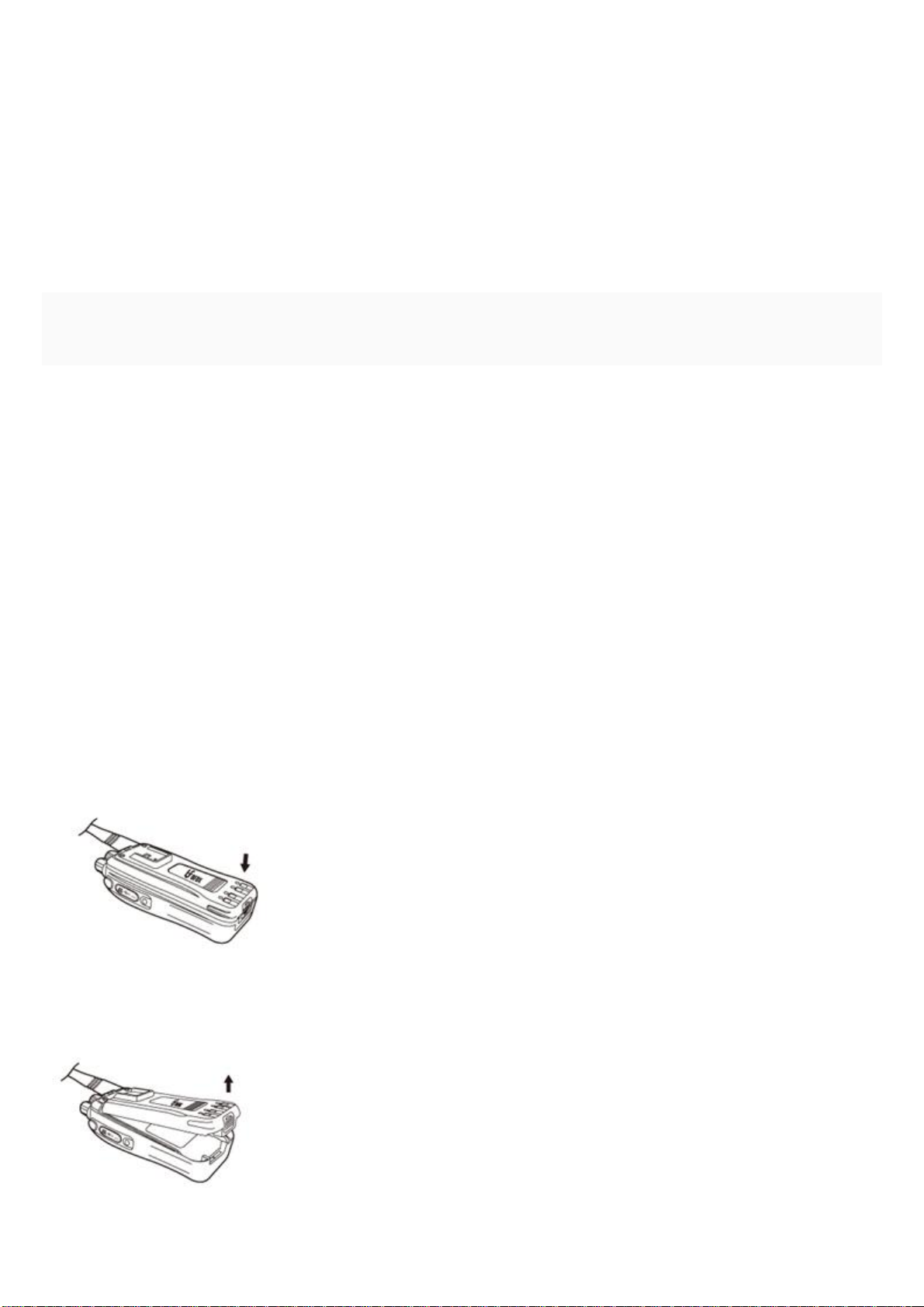
1. Press the battery pack behind the radio, push it in till you hear a “kada” sound, the battery pack will
be locked.
2. Press the latch at the bottom of the battery pack to take it off on the upward direction.
4
Page 5
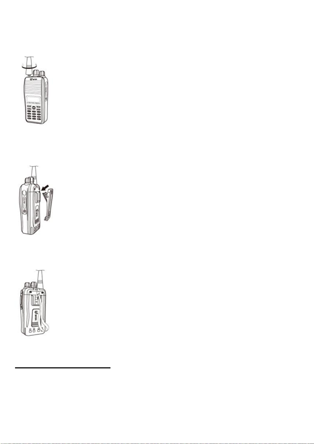
Install the antenna
Hold the bottom of the antenna, spin the antenna into the connector of the radio with clockwise, till it is
fixed.
Install the belt clip
Put the belt clip into the grooving slot, push it in till you hear a “kada” sound, the clip will be locked
Install the hand strap
Put the hand strap through the loop of the radio.
Getting acquainted
5
Page 6
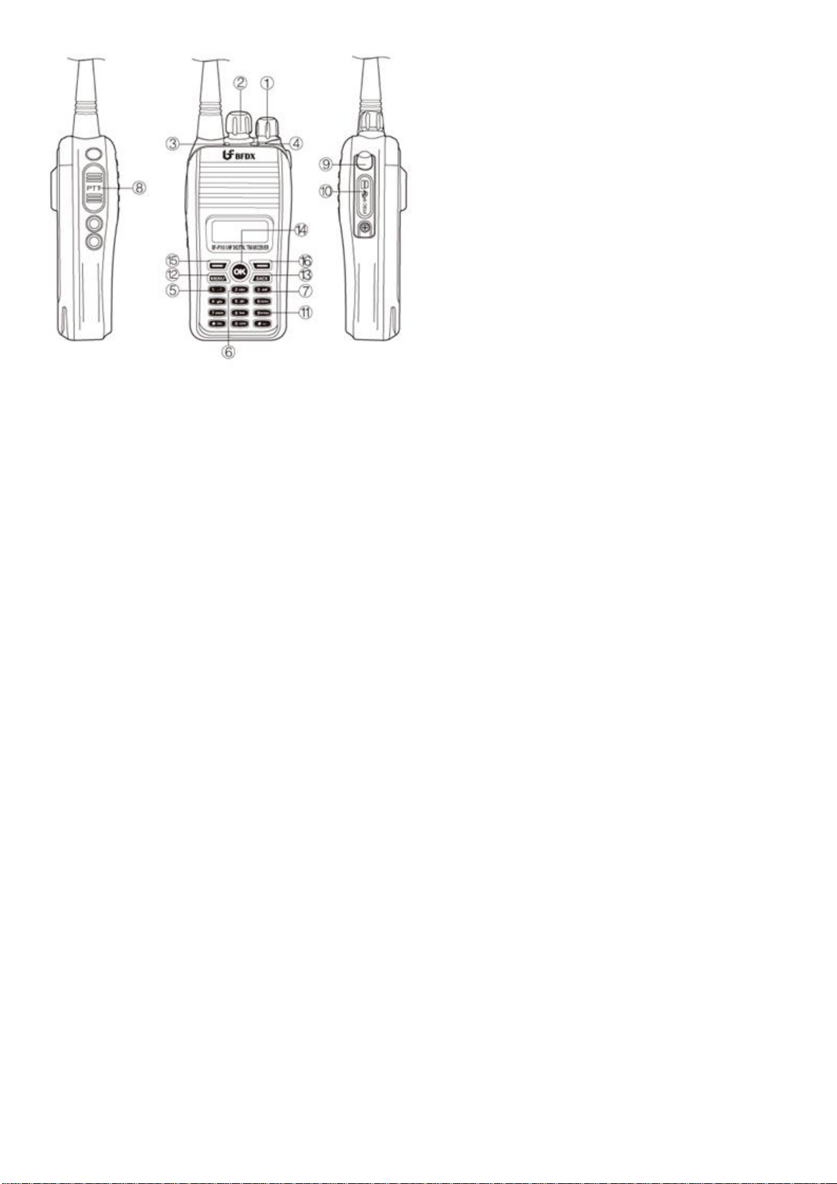
1. Power on/off and volume adjuster
1)Turn the knob clockwise then the power will turn on, it can adjust the volume after turn on. Voice
channel broadcasting will be heard if mute cancelled, if no activity detected on the channel, instead of
voice channel broadcasting, a short voice will appear
2)Turn the knob counter-clockwise, it will turn off the power.
2. Channel knob
1)rotate the knob to select the channel according to zone, 16 channel included in each zone, If the
channel programmed, tone alert will be heard, if does not programmed there will be a short voice alert.
2) if the radio is in the state of in establishing a connection, change channel will cause signal
disconnected
3, LED indicator
1) light red for transmitting
2) Light green for receiving
3) Light red, green and orange turn on respectively when turn on the radio
4) Red and green light become alternant flicker when channel is not programmed
5) Orange light flicker when phase locked loop got unlocked
4. Orange button
user-programmable (see below for details)
5. Button 1
user-programmable (see below for details)
6. Button 2
user-programmable (see below for details)
7. Button 3
user-programmable (see below for details)
8. PTT
6
Page 7

Press and hold the PTT button then you can speak and transmit.
9. MIC-SP-USB connection
Connection for MIC-SP and USB cable
10. MIC-SP-USB fixer
To keep good connection between USB cable and MIC/SP
11. Keypad
For alphabet and Numbers key in
12. Menu button
For radio’s function setting
13.Back button
Return key
14.OK button
Confirm button
15.left“—”turn to left
16.right“—”turn to right
Operation Basics
Switching power ON/OFF
Turn the power switch/volume control clockwise to switch the radio ON.
Turn the power switch/volume control counterclockwise to switch the radio OFF.
Adjusting the volume
Rotate the power switch/volume control to adjust the volume clockwise increase the volume and
counterclockwise decreases.
When talk to others, it is need adjust the volume exactly
Note: When adjusting the volume, the volume of voice channel broadcasting keep unchanged.
Channel knob
Select channel 1-16 by rotating the channel knob
voice channel broadcasting: voice channel broadcasting for channel No. will be heard when
rotating channel knob, meanwhile, the channel No. channel zone, high/low power and exact
frequency both for transmitting and receiving will also displayed on the screen.
Transmitting
Hold on the PTT button then speak to the microphone, indicator light red
Please keep about 3-4cm to the microphone, speak with the normal tone, it can get the best effect
for the receiver.
When pressing the PTT, the LED turn red.
When pressing the PTT, call details such as channel No, frequency etc. will displayed on the
screen
Released the PTT can be received.
Receiving
LED indicator turn green in the case of channel indicated by the channel knob is called, only the
radio with the matched address ID can hear the call, radio will display receiving frequency, the
7
Page 8

other call type and number upon a signal received
Emergency Alarm Indication
1. Determines if audio and visual indication is given by the radio when an emergency alarm is received.
If the checkbox is unchecked, the radio displays nothing when it receives an emergency alarm.
2. Emergency Alarm Ack
Determines if the radio is allowed to acknowledge an emergency alarm. This is a channel-wide feature
3. Emergency Call Indication
Determines if a visual indication is given by the radio when an emergency call is received. This is a
channel-wide feature.
Radio features
General Settings
1. Radio Name
Sets an alias for the radio. This alias shows up as the welcome text when the radio powers up. The
user may enter up to a maximum of 8 characters. Valid characters are alphanumerics, spaces and
special characters. Support Chinese and English.
2. Program password
programming password is to prevent others login in radio, The user may enter up to a maximum of 8
characters. Valid characters are alphanumerics, spaces and special characters. Factory default:
123456
3. Radio ID
Sets an individual ID that uniquely identifies the radio. This ID is used by other calling radios when
addressing the radio, for instance, when making a private call or sending a text message.
Valid setting for radio ID is 7 digital numbers, only calling ID is consistent with the target ID can be
decoded (receiving mode)
4. Group ID
Valid setting for group ID is 7 digital numbers, only calling ID is consistent with the target ID can be
decoded (receiving mode)
5. Repeater ID
Valid setting for repeater ID is 7 digital numbers, only calling ID is consistent with the target ID can
be decoded (transmitting mode)
6. TX Preamble Duration (ms)
Preamble is a string of bits added in front of a data message or control message (Text Messaging,
Location Messaging, Registration, Radio Check, Private Call, etc…) before transmission. This
preamble prolongs the message in order to reduce the chances of the message being missed by the
receiving radio. The Transmit (TX) Preamble Duration sets the duration of the preamble. This
duration needs to be increased as the number of scan members increases on the target radio. This
value can be increased in all the transmitting radios if scanning radios are often missing data
messages. However, a larger preamble occupies the channel longer. Therefore, increasing the
Transmit Preamble duration will increase the success rate of data received while other radios are
scanning, but will decrease the amount of data that can be transmitted on the channel. Range
Maximum 8640 ms Minimum 0 ms Increment 240 ms
8
Page 9

7. Talkaround Group Call Hang Time (ms)
Sets the duration during which a radio will talk back to a received call or continue a transmitted
Talkaround Group Call using the previously received or previously transmitted digital group
ID. After expiration of the Talkaround Group Call hang timer, the radio will transmit using the TX
Contact Name (digital group) specified for this channel in CPS.
8. Talkaround Private Call Hang Time (ms)
Sets the duration the radio keeps the Talkaround Private Call setup after the user releases the
Push-to-Talk (PTT) button. This is to avoid setting up the call again each time the user presses the
PTT to transmit. During this time, other radios can still transmit since the channel is essentially idle.
After the hang timer expires, the radio transmits using the TX Contact Name specified for this
channel in CPS.
9. Access authentication
Digital radio have two working modes: normal working mode and safety working mode, these setting
only valid during repeater mode.
1 normal working mode, handheld only need to send request of “establish connection” to the repeater,
the channel will be available after connection succeed, and all the radios connected to this repeater
can communicate with each other, repeater will keep this working mode until Intentional disconnect or
beyond TOT range, this mode can make connection between radios quickly.
2, safety mode: handheld A send a request of ““establish connection” to the repeater, repeater send
this request to handheld B, the channel will be available after connection succeed, repeater reply a
confirm signal to handheld A, A and B can communicate with each other.
10. Battery Saver
●Enabling this feature causes an idle radio to automatically enter battery saver mode where it
places certain radio functions on standby. After a certain duration or when there is any user button
action, the radio returns to normal operation and checks the channel for incoming calls. If no calls
are detected, it returns to the battery saver mode. While results vary across battery chemistry and
user conditions, battery saver can deliver about a 10% improvement in battery life, but also causes a
delay in response time.
●When this feature is enabled, it is important to note that for the transmitting radios, there will be a
slight delay in call setup (in the range of milliseconds) when pressing the Push-to-Talk (PTT) button.
For the receiving radios, there may be an increase in late entry due to radios in battery saver mode
having less opportunity to properly synchronize. This may cause the radios to miss the initial second
of some audio transmissions in poor radio frequency (RF) conditions. This, however, will not be
experienced in good RF coverage. Although they are important to note, these delays are considered
minor versus the 10% improved battery life, therefore it is recommended to enable battery saver
mode for all radios.
11. Disable All LEDs
Turns off all LEDs during radio power up (except for repeater) and while radio is in use. All LEDs
are disabled including the backlight and power up LED, regardless of the backlight setting.
9
Page 10

12. DPMR mode 3
Multi-channel output mode
13. Always priority call
At the multi-channel mode, It is always in priority transmission and connection regardless of
channel is busy or idle
Tone alerts
1. Disable All
Allows the user to disable all alert tones (Keypad tones, Call Ringers, Escalert and Talk Permit Tone)
except for the incoming Emergency alert tone.
2. Escalert
The radio gradually increases the volume of a repetitive alert tone (for example, a repetitive tone on
an incoming call). The alert tone volume starts from a predefined minimum volume in the radio and
increases, by a constant step size, until the volume level reaches the maximum volume. This is a
radio-wide feature.
3. Channel Free Indication
This feature sounds an alert tone when a voice call ends. It also sounds when the voice call is
interrupted on the current channel, for example, by interruptions caused by a third radio making an
impolite call or sending an emergency alarm. However, this tone does not sound if the interruption
is caused by a corrupted radio signal. Voice calls include Group Call, Private Call, All Call, and
Emergency Call. A voice call ends when the user of the calling radio releases the Push-To-Talk
(PTT) button, regardless of hang time. This feature alerts the receiving radio that the channel is
available for him/her to respond producing a smoother flow of conversation. This alert tone does
not sound at the end of a Remote Monitor transmission, or during Priority Scan when the voice call
ends while the radio is sampling the priority channel(s). This is a radio-wide feature.
4. Talk Permit
This alert tone sounds after the Push-to-Talk (PTT) button is pressed and the radio is able to
transmit on the channel. This is to prompt the user to begin speaking.
5. Volume Offset (dB)
Sets an offset level for the alert tone volume. Setting this causes the alert tone volume level to be
constantly higher, lower, or equal to the audio volume level controlled by the radio's volume knob.
●RX Low Battery Interval (sec)
10
Page 11

●The Receive (RX) Low Battery tone is an alert tone that sounds when the radio’s low battery
threshold is reached while a call is being received, or while the radio is in idle mode. The RX Low
Battery Interval sets the interval for the generation of this tone.
Range
Maximum 635 sec Minimum 0 sec Increment 5 sec
Menu
1. Menu Hang Time (sec)
Sets the amount of time that the radio remains in the menu mode, after which the radio reverts back
to the Home screen. If the duration is set to 0, radio remains infinitely in this mode. This is a
radio-wide feature. Range
Maximum: 30 sec Minimum: 0 sec Increment: 1 sec
2. Text Message
Allows the user to access the Text Message feature via the menu. The user has the ability to check
the Inbox, edit messages, send messages or Quick Text.
Contact List
1. Call indicating
Allows the user to initiate Call Alert via the menu. Call Alert allows the user to alert another user,
requesting that they call back the user (call initiator) when they (recipient) become available. Call
Alert can only be received when the channel is free. In Digital Mode, the user can only initiate a Call
Alert to an individual radio. In Analog mode, the destination ID can be a Private, Group or All Call ID
2. Edit
Allows the user to edit the alphanumeric characters on the edit screen. The user has the ability to
add a new entry to the Contacts list or edit an entry within the Contacts list.
3. Manual Dial
Allows the user to access the Manual Dial capability of the radio via the menu. Manual Dial allows
the user to initiate a call (e.g. Private Call, Call Alert) or request (e.g. Remote Monitor, Radio Check,
Radio Disable, Radio Enable) or send Text Messages by keying in the destination ID using the
keypad, even if the destination ID is not listed in the Contacts.
4. Radio Check
Allows the user to initiate a Radio Check request from the menu. Radio check allows a
user/console operator to determine if a radio is active in a system without showing any indication to
the radio's user.
11
Page 12
5. Remote Monitor
Allows the user to initiate a Remote Monitor request to the target radio via the menu. Upon a
successful request, the target radio's microphone and transmitter will be activated to be remotely
monitored.
6. Radio Disable
Allows the user to initiate a Radio Disable command to the target radio via the menu. Upon a
successful request, the target radio will disable all its user interfaces (e.g. all LED indicators
including Backlight, alert tones, user inputs including PTT except for Volume/On/Off knob on
Portable and Power On/Off button on Mobile), ignore Emergency alarms and received data to radio
or external devices, mute received voice to radio or external device and disallow transmission of
data or command from the radio or external device. This disables the radio if it is lost or stolen.
However, the radio continues to monitor the air interface to enable it to receive the Radio Enable
command.
7. Radio Enable
Allows the user to initiate the Radio Enable command to the target radio via the menu. Radio
Enable is used to enable a target radio that is disabled (inhibited).
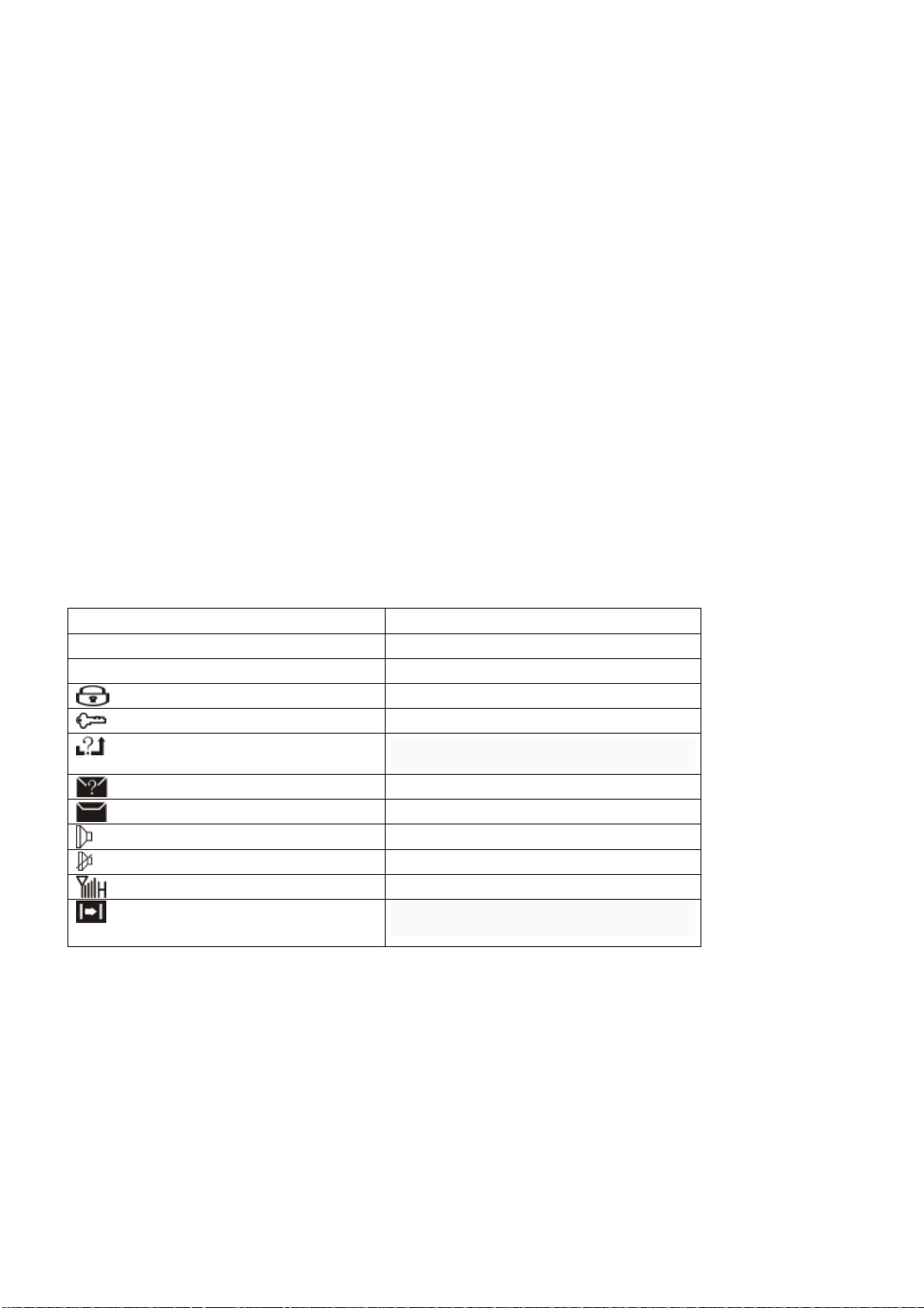
Radio mark explaination
H/L High/low output
E2 Repeater mode
E3 Multi-channel mode
Keypad lock
Access authorization
Missed Calls
Missed SMS
SMS full
Speaker open
Speaker close
Signal strength bar
Voice sign
Scan
●Allows the user to toggle Scan on or off via the menu for the current channel. Scan allows the radio
to search the scan list that is attached to the current channel for an eligible channel to receive or
unmute.
●Edit List
Allows the user to edit the Scan List via the menu. The Edit List allows the user to perform certain
12
Page 13

actions on the scan list, e.g. view the scan list, change the scan member's priority level, add new scan
members to the scan list or delete members from the scan list. Creating a new or deleting an existing
scan list is not allowed on the radio
Call log
●Missed
Allows the user to track the last 10 incoming private calls that the user missed or failed to respond.
The user accesses the call log via the menu. This log also provides a quick way for the user to initiate
a private call.
●Answered
Allows the user to track the last 10 incoming private calls that the user answered. The user accesses
the call log via the menu. This log also provides a quick way for user to initiate a private call
●Outgoing
Allows the user to track the last 10 private call numbers that the user initiated and provides easy redial
access. The user accesses the call log via the menu. This log also provides a quick way for the user to
initiate a private call.
Setting
1. language environment
It support Chinese and English operating mode
2. Talkaround
Allows the user to set the radio in Talkaround mode via the menu. Talkaround mode is required in the
absence of a repeater
3. Tones/Alerts
Allows the user to toggle all the tones and alerts on or off via the menu.
4. Power
Allows the user to adjust the radio's transmission power level via the menu.
5. Backlight
Allows the user to change the Backlight setting via the menu, such as off, atuto, on
6. Intro Screen
Allows the user to enable or disable the Introduction Screen upon radio power up via the menu.
If enabled, the Radio Name shows as the welcome text when the radio powers up
7. Keypad Lock
Allows the user to toggle the keypad lock on or off via the menu.
13
Page 14

8. LED Indicator
Allows the user to toggle the radio's LED indicator on or off via the menu
Signaling system
Signaling system can be ignored
Button definition
Long Press Duration (ms)
Sets the duration a button is required to be pressed (and held down), for it to be interpreted as a
long press, tone alert will be heard for effective short or long press
Range : Maximum 3750 ms Minimum 250 ms Increment 250 ms
Button function
1. All Alert Tones On/Off: Allows the user to enable or disable all the alert tones simultaneously.
2. Battery Indicator: Allows the user to check the status of the battery charge via the LED. Solid
Green indicates high battery level, Solid Yellow indicates fair battery level and Flashing Red
indicates low battery level
3. Emergency Off: Allows the user to terminate an outgoing emergency call.
4. High/Low Power: Allows the user to toggle between high and low power.
5. Monitor: Allows the user to toggle the Monitor feature between on or off. The Monitor feature
allows the user to monitor a channel. In Analog mode, the user is able to listen to the traffic, i.e. the
radio will unmute to the actual voice or data traffic in process. However, in Digital mode, the user can
only check if activity is present before transmitting, i.e. the radio will emit an audible/visual alert if there
is activity present, but it will not unmute to the actual voice or data traffic in process.
Permanent Monitor:
6. Permanent Monitor:it has the same function as Monitor (Portable only), which is to allow the user
to listen to the channel to ensure that there is no activity on it before transmitting. The difference is, for
Permanent Monitor, once entered, the radio remains in that mode until a button is pressed again to
exit the feature.
7. Nuisance Delete: Allows the user to temporarily remove an unwanted channel from the scan list,
except the Selected Channel. The nuisance deleted channel will be restored into the scan list, for
instance, when radio is powered off and back on again.
8. Manual Dial For: Provides the user with the flexibility to dial any private number that is unavailable
in Contacts (applicable to Digital mode, Display model only).
9. Contacts: Allows the user to access the Contacts list (MDC or Digital - depending on the radio's
current channel) to make a call or initiate any supplementary call features
10. One Touch Call 1: Allows the user to make a digital Group Call, digital Private Call, Call Alert or
send a Quick Text via a One Touch Call (applicable to Digital mode only).
11. One Touch Call 2:Refer to One Touch Call 1 functionality. This is another option that can be
configured as One Touch Call (applicable to Digital mode only
12. One Touch Call 3:Refer to One Touch Call 1 functionality. This is another option that can be
configured as One Touch Call (applicable to Digital mode only
13. One Touch Call 4:Refer to One Touch Call 1 functionality. This is another option that can be
configured as One Touch Call (applicable to Digital mode only
14
Page 15

14. One Touch Call 5:Refer to One Touch Call 1 functionality. This is another option that can be
configured as One Touch Call (applicable to Digital mode only
15. One Touch Call 6:Refer to One Touch Call 1 functionality. This is another option that can be
configured
16. Repeater/Talkaround: Allows the user to toggle between Repeater and Talkaround mode.
17. Unassigned: No feature is assigned to the programmable button.
18. Zone Selection: Allows the user to access the Zone menu to change zone (applicable to Display
model only).
19. Scan On/Off: Allows the user to toggle the Scan feature between on or off.
20. Access authentication on/off: allows the user work on normal working mode or safety working
mode
21. Disconnect: allows the user to disconnect from the repeater intentionally.
Note: the above function can achieved by short or long press
Keypad
1. Orange Button Short Press
Allows the user to change the short press functionality of the Orange Button
2. Orange Button Long Press
Allows the user to change the long press functionality of the Orange Button
3. Button 1 Short Press
Allows the user to change the short press functionality of the Button 1
4. Button 1 long Press
Allows the user to change the long press functionality of the Button 1
5. Button 2 Short Press
Allows the user to change the short press functionality of the Button 2
6. Button 2 long Press
Allows the user to change the long press functionality of the Button 2
7. Button 3 Short Press
Allows the user to change the short press functionality of the Button 3
8. Button 3 long Press
Allows the user to change the long press functionality of the Button 3
Configuring One Touch Calls
1. Allows the user to make a Group Call, Private Call, Call Alert or send Quick Text with one touch of a
button. One Touch Call can be assigned to a short or long programmable button press (One Touch
Call).
2. To configure a One Touch Call before assigning it to a programmable button:
Select a call member in the Digital Call column.
Select the type of call in the Call Type column.
If Text Message is chosen, select the text message in the Text Message column.
15
Page 16

3. Digital Call
Allows the user to select a call member from all types of digital calls available in the Digital folder
under Contacts, i.e. Private Calls, Group Calls, PC calls and Dispatch Calls except All Call.
4. Call Type
Allows the user to select a call type for the call member that was selected in the Digital Call column.
Text Message
1. Allows the user to select a Quick Text. The selection for these messages comes from Text
Messages.
2. This feature allows for text messages to be predefined. These messages (also known as Quick Text
messages) are common messages that are sent repeatedly and stored in the radio. This helps the
user avoid retyping content whenever they want to send a text message. A maximum of 10 messages
may be added to the Quick Text message list. For a Display model radio, the user can send access the
Text Message feature via the Text Messages menu or a short or long programmable button press
assigned to Text Message. For a Non-Display or Numeric Display model radio, the user can only send
a Quick Text message by pressing a short or long programmable button assigned to One-Touch Call.
It does not have a menu to receive or display incoming text messages or to select Quick Text
messages.
Entering Text Messages
●A user may enter up to a maximum of 140 characters. Valid characters are alphanumerics, spaces
and special characters. The user can send the text message by assigning a short or long
programmable button press (Text Message) or access the Text Messages feature via the Text
Messages Menu feature.。
●This feature allows for text messages to be predefined. These messages (also known as Quick Text
messages) are common messages that are sent repeatedly and stored in the radio. This helps the
user avoid retyping content whenever they want to send a text message. A maximum of 10 messages
may be added to the Quick Text message list. For a Display model radio, the user can send access the
Text Message feature via the Text Messages menu or a short or long programmable button press
assigned to Text Message. For a Non-Display or Numeric Display model radio, the user can only send
a Quick Text message by pressing a short or long programmable button assigned to One-Touch Call.
It does not have a menu to receive or display incoming text messages or to select Quick Text
messages.
Emergency Systems
A Digital Emergency system is a signaling protocol used by the radio for communication during
emergency when the radio is in Digital Mode. A maximum of 4 Digital Emergency systems can be
created.
1. To add a Digital Emergency system:
Right-click the Digital Emergency folder of the Tree View.
16
Page 17

Select Add->System.
2. To delete a signaling system:
Right-click an individual signaling system of the Tree View.
Select Delete.
Alarm Type
An alarm is a non-voice signal that triggers an alert indication on another radio. This feature specifies
the behavior of the radio's alarm when the emergency button is pressed
1. Disabled: The radio is unable to transmit an alarm signal.
2. Regular:The radio transmits an alarm signal and provides audio and visual indication that it is in
Emergency mode.
3. Silent:The radio transmits an alarm signal but gives no audio or visual indication that it is in
Emergency mode. In addition, it will not unmute to any received audio.
4. Silent w/ Voice:The radio transmits an alarm signal but gives no audio or visual indication that it is in
Emergency mode. The radio then unmutes to qualified channel activity
Mode
Defines the radio’s behavior when the radio's emergency button is pressed.
1. Emergency Alarm: The radio sends an emergency alarm and exits the emergency mode.
This alarm is a non-voice signal that triggers an alert indication on another radio.
2. Emergency Alarm w/ Call: An emergency alarm is sent, after which an emergency call can be
transmitted by pressing the Push-To-Talk (PTT) button.
3. Emergency Alarm w/ Voice to Follow:This option enables the Hot Mic feature, allowing for
the programming of the Hot Mic related features, i.e. Hot Mic Duration. An emergency alarm is
sent and the microphone is activated for an emergency call. Voice is transmitted without the
need to press the Push-To-Talk (PTT) button.
Impolite Retries
An impolite transmission is a transmission that occurs even when there is activity on the current
channel. The radio tries a number of impolite transmissions to get an acknowledgement and
then goes on to try a number of polite transmissions. This feature sets the number of attempts to
transmit an emergency alarm impolitely
Range:Maximum 15 Minimum 1 Increment1
Polite Retries
A polite transmission is a transmission that occurs only when the current channel is free of
activity. The radio tries a number of impolite transmissions to get an acknowledgement before
trying a number of polite transmissions. This feature sets the number of attempts to transmit an
emergency alarm politely.
17
Page 18

Hot Mic Duration (sec)
If the Mode is selected as Emergency Alarm with Voice to Follow, after the radio transmits an
emergency alarm, the Hot Mic feature is activated whereby the radio automatically begins
transmitting voice for the duration indicated by the Hot Mic Duration. There is no need to press
the Push-To-Talk (PTT) button during this time in order to transmit voice. Once this duration
expires, the radio automatically dekeys. The call made during this duration is an emergency call
Menu operation
1. Contact list
▼Click the "MENU" button, press the left key "—" or right key "—" key to find contact list,
press button "OK" to confirm and enter the contact list settings, .Press button "BACK" to exist
this operation.
▼Add contact member: enter contact list, press the left key "—" or right key "—" key to find
“creating new call members”, press button "OK" to confirm and enter the settings,
▼Manual Dial: enter contact list, press the left key "—" or right key "—" key to find “manual
dial” Allows the user to access the Manual Dial capability of the radio via the menu. Manual Dial
allows the user to initiate a call (e.g. Private Call, Call Alert) or send Text Messages by keying in
the destination ID using the keypad, even if the destination ID is not listed in the Contacts.
2. Scan
▼Click the "MENU" button, press the left key "—" or right key "—" key to find “scan”, press
button "OK" to confirm and enter scan settings, .Press button "BACK" to exist this operation.
▼Scan on or off: enter scan, press the left key "—" or right key "—" key to find “scan”, press
button "OK" can select on or off. Allows the user to toggle Scan on or off via the menu for the
current channel. Scan allows the radio to search the scan list that is attached to the current
channel for an eligible channel to receive or unmute.
▼View/edit list: same setting as above. Allows a user to designate the current channel as
priority channel or list the current channel in the selection of add or delete .through menu
operation.
3. zone
Click the "MENU" button, press the left key "—" or right key "—" key to find “zone”, press
button "OK" to confirm and enter zone settings, .Press button "BACK" to exist this operation.
▼the user can change to a different zone via menu operation
4. text message
▼ Click the "MENU" button, press the left key "—" or right key "—" key to find “text message”,
press button "OK" to confirm and enter text message settings, .Press button "BACK" to exist
this operation.
▼ Entering Text Messages: A user may enter up to a maximum of 80 characters. Valid
characters are alphanumerics, spaces and special characters. The user can send the text
message by assigning a short or long programmable button press (Text Message) or access the
Text Messages feature via the Text Messages Menu feature.
18
Page 19

▼ Quick Text messages: This feature allows for text messages to be predefined. These
messages (also known as Quick Text messages) are common messages that are sent
repeatedly and stored in the radio. This helps the user avoid retyping content whenever they
want to send a text message.
▼ Sent messages: A maximum of 10 messages can be added to the Quick Text message list,
otherwise will be automatically deleted.
▼ Message box: A maximum of 50 messages can be preserved in the message box.
5. Message key-in method
▼. The key "0" is for English alphabet, numbers and Chinese characters switching in message edit
mode
▼. In Chinese characters mode, press "#" can change to the next row "
▼. Send out the finished message to any digital No. by press "OK"
6. Call log
▼Click the "MENU" button, press the left key "—" or right key "—" key to find “call log”, press
▼button "OK" to confirm and enter call log settings, .Press button "BACK" to exist this
operation.
▼Missed: Allows the user to track the last 10 incoming private calls that the user missed or
failed to respond.
▼Answered: Allows the user to track the last 10 incoming private calls that the user answered.
▼Outgoing: Allows the user to track the last 10 private call numbers that the user initiated and
provides easy redial access.
7. General setting
▼ Click the "MENU" button, press the left key "—" or right key "—" key to find “general
setting”, press button "OK" to confirm and enter general settings, .Press button "BACK" to exist
this operation.
▼ language, talkaround, tone/alert, output power, backlight, Intro Screen, keypad lock, lED
on/off can be activate at general setting mode
Contact list
1. Private Call(P): A call from an individual radio to another individual radio.
2. Group Call(G): A call from an individual radio to a group of radios.
3. All Call(A): A one-way call from an individual radio to every radio on that channel. All Calls do not
communicate across different timeslots or channels within the system. The ability to initiate an All Call
is only programmed into radios that are used in supervisory roles. All other radios monitor All Call
transmissions by default. This feature is very useful when a supervisor needs to communicate with all
the users on a logical channel, rather than just a particular group or individual.
4. Repeater call:(R) A call from an individual radio to the repeater
19
Page 20

Channel
This radio house 50 zones, each zone support 16 channels and the total 160channel supportable.
1.To add a zone:
Right-click the Channels folder of the Tree View.
Select Add->Zone to create a zone.
Give the zone a unique name. Valid characters are alphanumerics, spaces and special characters. An
empty string cannot be used for a name.
2.To add a channel in the zone:
Right-click the zone.
Select Add-> Digital Channel to create a Digital channel.
Give the channel a unique name. Valid characters are alphanumerics, spaces and special characters.
An empty string cannot be used for a name.
Deleting Zones and Channels
3. To delete a zone:
Right-click the zone folder of the Tree View.
Select Delete.
Click the Yes button when prompted with a confirmation box. The zone is removed.
4. To delete a channel:
Right-click an individual channel of the Tree View.
Select Delete.
Click the Yes button when prompted with a confirmation box. The channel is removed.
Scan Function
1. Scan list
Associates a Scan List to this channel. All the members on this list will be scanned during a scan
operation. Any available Scan List can be selected. Selecting the None option disables scanning
(including Auto Scan) on this channel.
2. Auto Scan
20
Page 21

Allows the radio to automatically begin scanning when the user selects the current channel. When
disabled, the user is still able to invoke the scan operation, via a short or long programmable
button press (Scan On/Off) or Scan (Scan Menu) feature.
3. Color Code
This feature allows a color code to be assigned to a given channel. Channels may have the same or
different color codes. A repeater can only have one color code. A color code is used to identify a
system. Different color codes are used to identify different systems. This feature enables a radio to
roam between multiple systems by switching between channels with different color codes. The radio
will be able to scan across channels with different color codes. Radios will ignore any channel activity
not containing the matching color code for that system. Repeaters using the same frequency may be
associated with different color codes. On shared channels, spectrum regulators may wish to assign
different color codes to different licensees as part of their license agreement, range: 1-15
4. Allow Talkaround
Ensures that the Receive parameters are used in place of the Transmit parameters when
transmitting. This feature enables communication between radios in close proximity without the use
of a repeater, and is, therefore, particularly useful when the radios are in close proximity and the
repeater is out of range. This feature can be toggled between Repeater or Talkaround mode, via a
short or long programmable button press (Repeater/Talkaround) or Talkaround (Utilities Menu)
feature.
Note: For a Digital channel, the Transmit and Receive frequencies must be the different for this
feature to be enabled.
5. Receive (RX) Only
Configures the channel to receive only without any transmission capability. All Transmit features for
the channel will also be disabled.
6. Offset (MHz)
Creates a Transmit Frequency from the Receive Frequency with an added Offset value. This ensures
that a radio's offset is consistent with the repeater's offset. A user may enter up to a maximum of 14
digits or characters, including the decimal point and negative sign (e.g. -12.025). Clicking on the Copy
button will populate the Transmit side.
7. Copy
Adds the Offset to the Receive Frequency to generate the Transmit Frequency. For an Analog channel,
this feature also copies all the Receive parameters, i.e. features inside the RX box such as the
Frequency (MHz), Squelch Type, Digital Private Line (DPL) Code (Octal), DPL Invert, Tone Private
Line (TPL) Frequency (Hz), TPL Code and Signaling System to the Transmit side. For a Digital
channel, the RX box has only the Receive Frequency (MHz) feature, therefore only this is copied to
the Transmit side.
21
Page 22

8. TX Frequency (MHz)
Sets a frequency (in MHz) on which a signal is transmitted for the current channel.
9. Default Frequency (MHz)
Selects the Reference Frequency used when transmitting on the current channel. The reference
frequency can be shifted to allow the radio to operate on channel frequencies that would otherwise
be blocked by internally generated spurious signals. Internally generated spurious signals would
appear as silent carriers on certain channel frequencies. Shifting the reference frequency allows
these permanent signal carrier to be shifted to unused frequencies so that the desired channel
frequencies can still be used. The options are Default, 5.6MHz or 8.4MHz
10. Emergency System
Associates any available digital emergency system to this channel for use during an emergency.
Selecting the None option disables the user from transmitting an emergency call from this channel.
Notes:
Configure the Digital Emergency system under the signaling systems folder before selecting it or the
default will be used.
The RX Only feature must be disabled.
11. Power Level
Sets the radio’s transmission power level for this channel. This feature can be toggled between high or
low, via a short or long programmable button press (High/Low Power) or Power (Utilities Menu)
feature.
Notes
High Used when a stronger signal is needed to extend transmission distances.
Low Used when communicating in close proximity, and to prevent transmissions into other
geographical groups.
For UHF Portable, Low Power is equivalent to 1W and High Power is equivalent to 4W. For Mobile and
Repeater, the High and Low values are configurable through the TX High Power (W) and TX Low
Power (W) features under General Settings.
12. TOT (sec)
The Time-Out Timer (TOT) is the duration that the radio can continuously transmit before
transmission is automatically terminated. This feature is used to ensure the channel is not
monopolized by any one radio. The user may set smaller time-outs for busier channels.
Range
22
Page 23

Maximum 495 sec (for digital channels in Portables and Mobiles)
13. TOT Rekey Delay (sec)
Sets the amount of time that the radio waits on a channel after the Time-Out Timer (TOT) expires
(which stops the radio transmission) before allowing the user to transmit again. This is a
channel-wide feature.
Range
Maximum 255 sec Minimum 0 sec Increment 1 sec
14. Admit Criteria
Determines when voice or data is allowed to be transmitted on the channel. This is used to prevent a
radio from transmitting on channels that are already being used. If the radio has different transmit and
receive frequencies, only the receive frequency is monitored for activity. If no activity is found on the
receive frequency, the radio allows the user to transmit on the transmit frequency even if it is being
used.
Options
▼Always: The radio will always transmit when the Push-to-Talk (PTT) button is pressed. This option is
also referred to as "Impolite" channel access.
▼Channel Free: The radio will check for an idle channel prior to allowing a transmission. This option is
also referred to as "Polite to All" channel access.
▼Color Code Free: The radio will check if the specified Color Code is not in use prior to allowing
transmission (except for Group Calls that are already in progress). This option is also referred to as
"Polite to Own Digital System" channel access (for Digital channels only).
Scan
Adding Scan Lists
A Scan List is a grouping of channels to be monitored for transmission activity. When this list is
attached to a channel (Channels->Scan List), the radio searches the list for an eligible channel to
receive or unmute during a scan operation. This is also known as a Channel Scan. A maximum of 32
scan lists can be created. Each list can contain a maximum of 15 members.
1. To add a Scan List:
Right-click the Scan folder of the Tree View.
Select Add->Scan List.
Give the list a unique name.
2. Deleting Scan Lists
23
Page 24

To delete a Scan List:
Right-click an individual Scan List of the Tree View.
Select Delete.
3. Hang Time (ms)
Sets the time the radio will remain on a scan list member channel following the end of the channel
activity. The hang time prevents the radio from resuming scanning until the conclusion of the response
to the initial call. The timer starts at the end of a transmission and resets whenever a valid activity is
detected on the channel during the hang time.
Range
Maximum 10000 ms Minimum 500 ms Increment 500 ms
4. Priority Alert
This is an alert tone that the radio emits when it unmutes to a priority channel during a scan operation.
Scan group function
Adds channel(s) from the Available list into the Members list. Channel(s) in the Members list will be
scanned for transmission activity during a scan operation. Channel(s) added to the Members list will
be removed from the Available list. A maximum of 15 channels (including the Selected channel) may
be added to a Members list.
1. To add a Scan List:
Right-click the Scan folder of the Tree View.
Select Add->Scan List.
Give the list a unique name.
Deleting Scan Lists
2. To delete a Scan List:
Right-click an individual Scan List of the Tree View.
Select Delete.
3. Adding Scan Members
Select channel(s) from the Available list and click option “add”(A)
4. Removing Scan Members
Select the selected channel(s) from the Members list. and click option “Remove”(R), the channel will
return to the Available list.
24
Page 25

5. Talkback
Determines if the user is able to transmit on the channel it unmutes during scan. If this feature is
disabled, the radio transmits on the channel indicated by the TX Designated Channel feature.
6.Set/Clear Priority 1
Toggles the Priority 1 scanning status of the highlighted channel in the Members list. When the Priority
1 status is set to the highlighted channel, the Priority 1 status on another channel (if any) is cleared.
During scan, 50% of a radio's scans are on the Priority 1 channel. If a Priority 2 channel exists, scans
for the Priority 1 member are reduced from 50% to 25%. Even after landing on a non-priority or Priority
2 channel, the radio continues to periodically scan for transmission activity on a Priority 1 channel. If
the radio discovers activity on the Priority 1 channel, it drops the current transmission, and unmutes to
the Priority 1 channel.
7. Set/Clear Priority 2
Toggles the Priority 2 scanning status of the highlighted channel in the Members list. When the Priority
2 status is set to the highlighted channel, the Priority 2 status on another channel (if any) is cleared.
During scan, 25% of a radio's scans are on the Priority 2 channel. If a Priority 2 channel exists, scans
for the Priority 1 member are reduced from 50% to 25%. Even after landing on a non-priority channel,
the radio continues to periodically scan for transmission activity on a Priority 2 channel. If the radio
discovers activity on the Priority 2 channel, it drops the current transmission, and unmutes to the
Priority 2 channel. Activity on a Priority 2 channel will be dropped in the event of any valid activity on a
Priority 1 channel.
8. TX Designated Channel
This feature defines the channel on which the radio will transmit if the user presses the Push-to-Talk
(PTT) button while the radio is scanning. If the Talkback option is disabled, this feature also defines
the channel where the radio will transmit if the user presses the PTT when the radio has stopped
scanning to unmute to an eligible scan list member. Any channel can be selected as the TX
Designated Channel. Alternatively, the Selected or Last Active Channel may be chosen.
9. Priority Sample Time (ms)
Sets the duration that the radio waits, when in a call, before scanning the priority channels. If the call is
taking place on a Priority 1 Channel, no scanning will take place. When scanning priority channels, the
radio briefly mutes the current transmission. Increasing this interval improves the audio quality of the
current transmission as fewer checks are done, but this also increases the chance of the radio missing
out priority channel activity.
Range
Maximum 7750 ms Minimum 750 ms Increment 250 ms
FCC Regulations
Federal Communication Commission (FCC) requires that all radio communication products
should meet the requirements set forth in the above standards before they can be marketed in the
U.S, and the manufacturer shall post a RF label on the product to inform users of operational
instructions, so as to enhance their occupational health against exposure to RF energy.
FCC Statement
25
This equipment has been tested and found to comply with the limits for a Class B digital device,
pursuant to part 15 of FCC Rules. These limits are designed to provide reasonable protection
against harmful interference in a residential installation. This equipment generates and can radiate
Page 26

Guidelines:
radio frequency energy and, if not installed and used in accordance with the instructions, may
cause harmful interference to radio communications. However, there is no guarantee that
interference will not occur in a particular installation. If this equipment does cause harmful
interference to radio or television reception, which can be determined by turning the equipment off
and on, the user is encouraged to try to correct.
The interference by one or more of the following measures:
1) Reorient or relocate the receiving antenna. Increase the separation between the equipment and receiver.
2) Connect the equipment into an outlet on a circuit different from that to which the receiver is connected.
3) Consult the dealer or an experienced radio/TV technician for help
Operation is subject to the following two conditions: 1. This device may not cause harmful
interference, and 2. This device must accept any interference received, including interference that
may cause undesired operation
Note:" Changes or modifications to this unit not expressly approved by the party responsible for
compliance could void the user's authority to operate the equipment."
Compliance with RF Exposure Standards
Beifeng's 2-way radio complies with the following RF energy exposure standards and guidelines:
o United States Federal Communications Commission, Code of Federal Regulations; 47 CFR §§ 1.1307, 1.1310 and 2.1093
o American National Standards Institute (ANSI) / Institute of Electrical and Electronic Engineers (IEEE) C95. 1-1992
o Institute of Electrical and Electronic Engineers (IEEE) C95.1-1999 Edition
RF Exposure Compliance and Control Guidelines and Operating Instructions
To control your exposure and ensure compliance with the occupational/controlled environment
exposure limits always adhere to the following procedures.
Guidelines:
o Do not remove the RF Exposure Label from the device.
o User awareness instructions should accompany device when transferred to other users.
o Do not use this device if the operational requirements described herein are not met.
Operating Instructions:
o Transmit no more than the rated duty factor of 50% of the time. To transmit (talk), push the
Push-To-Talk (PTT) button. To receive calls, release the PTT button. Transmitting 50 % of the
time, or less, is important because this radio generates measurable RF energy exposure only when
transmitting (in terms of measuring for standards compliance).
o Hold the radio in a vertical position in front of face with the microphone (and the other parts of
the radio, including the antenna) at least one inch (2.5 cm) away from the nose. Keeping the
radio at the proper distance is important because RF exposures decrease with distance from the
antenna. Antenna should be kept away from eyes.
o When worn on the body, always place the radio in a Beifeng's approved clip, holder, holster, case,
or body harness for this product. Using approved body-worn accessories is important because the
use of Beifeng's or other manufacturer's non-approved accessories may result in exposure levels,
which exceed the FCC's occupational/controlled environment RF exposure limits.
o If you are not using a body-worn accessory and are not using the radio in the intended use
position in front of the face, then ensure the antenna and the radio are kept at least 2.5 cm (one
inch) from the body when transmitting. Keeping the radio at the proper distance is important
because RF exposures decrease with increasing distance from the antenna.
o Use only manufacturer's name approved supplied or replacement antennas, batteries, and
accessories. Use of non-manufacturer-name approved antennas, batteries, and accessories may exceed the FCC
RF exposure guidelines.
oFor a list of Beifeng's approved accessories (see the user manual), or (visit the following website
which lists approved accessories: http: add website address), or(The manufacturer should
include the appropriate bracketed item{s} in the manual.)
o For a list of Beifeng's approved accessories (see the user manual)
 Loading...