

Page 1

Page 1
Page 2

Page 2
1. RapMan 3.2 Operations Manual . . . . . . . . . . . . . . . . . . . . . . . . . . . . . . . . . . . . . . . . . . . . . . . . . . . . . . . . . . . . . . . . . . . . . . . . . . . . . . . . . . 3
1.1 1. Introduction . . . . . . . . . . . . . . . . . . . . . . . . . . . . . . . . . . . . . . . . . . . . . . . . . . . . . . . . . . . . . . . . . . . . . . . . . . . . . . . . . . . . . . . . . . . . 5
1.2 2. How this manual works . . . . . . . . . . . . . . . . . . . . . . . . . . . . . . . . . . . . . . . . . . . . . . . . . . . . . . . . . . . . . . . . . . . . . . . . . . . . . . . . . . . 6
1.3 3. Manual symbols . . . . . . . . . . . . . . . . . . . . . . . . . . . . . . . . . . . . . . . . . . . . . . . . . . . . . . . . . . . . . . . . . . . . . . . . . . . . . . . . . . . . . . . . 7
1.4 4. Process overview... how the RapMan 3 works . . . . . . . . . . . . . . . . . . . . . . . . . . . . . . . . . . . . . . . . . . . . . . . . . . . . . . . . . . . . . . . . . 8
1.5 5. Print material . . . . . . . . . . . . . . . . . . . . . . . . . . . . . . . . . . . . . . . . . . . . . . . . . . . . . . . . . . . . . . . . . . . . . . . . . . . . . . . . . . . . . . . . . . . 9
1.6 6. Pre-print checks . . . . . . . . . . . . . . . . . . . . . . . . . . . . . . . . . . . . . . . . . . . . . . . . . . . . . . . . . . . . . . . . . . . . . . . . . . . . . . . . . . . . . . . . 10
1.6.1 a. Clearing the print bed . . . . . . . . . . . . . . . . . . . . . . . . . . . . . . . . . . . . . . . . . . . . . . . . . . . . . . . . . . . . . . . . . . . . . . . . . . . . . . . 11
1.6.2 b. Check the print bed is fitted correctly . . . . . . . . . . . . . . . . . . . . . . . . . . . . . . . . . . . . . . . . . . . . . . . . . . . . . . . . . . . . . . . . . . . 13
1.6.3 c. Power up . . . . . . . . . . . . . . . . . . . . . . . . . . . . . . . . . . . . . . . . . . . . . . . . . . . . . . . . . . . . . . . . . . . . . . . . . . . . . . . . . . . . . . . . . 14
1.6.4 d. Test all axes . . . . . . . . . . . . . . . . . . . . . . . . . . . . . . . . . . . . . . . . . . . . . . . . . . . . . . . . . . . . . . . . . . . . . . . . . . . . . . . . . . . . . . 15
1.6.5 e. Check the hot-end nozzles are clean from plastic debris . . . . . . . . . . . . . . . . . . . . . . . . . . . . . . . . . . . . . . . . . . . . . . . . . . . . 17
1.6.6 f. Check the print bed is level . . . . . . . . . . . . . . . . . . . . . . . . . . . . . . . . . . . . . . . . . . . . . . . . . . . . . . . . . . . . . . . . . . . . . . . . . . . 18
1.6.7 g. Check the bed is referenced to the extruder nozzles . . . . . . . . . . . . . . . . . . . . . . . . . . . . . . . . . . . . . . . . . . . . . . . . . . . . . . . 20
1.6.8 h. Load the extruders . . . . . . . . . . . . . . . . . . . . . . . . . . . . . . . . . . . . . . . . . . . . . . . . . . . . . . . . . . . . . . . . . . . . . . . . . . . . . . . . . 21
1.6.9 i. Extruder control . . . . . . . . . . . . . . . . . . . . . . . . . . . . . . . . . . . . . . . . . . . . . . . . . . . . . . . . . . . . . . . . . . . . . . . . . . . . . . . . . . . . 23
1.6.10 j. Purge the extruder . . . . . . . . . . . . . . . . . . . . . . . . . . . . . . . . . . . . . . . . . . . . . . . . . . . . . . . . . . . . . . . . . . . . . . . . . . . . . . . . . 24
1.6.11 k. How to start a print . . . . . . . . . . . . . . . . . . . . . . . . . . . . . . . . . . . . . . . . . . . . . . . . . . . . . . . . . . . . . . . . . . . . . . . . . . . . . . . . 25
1.6.12 l. Double head calibration . . . . . . . . . . . . . . . . . . . . . . . . . . . . . . . . . . . . . . . . . . . . . . . . . . . . . . . . . . . . . . . . . . . . . . . . . . . . . 26
1.6.13 m. Print a successful raft . . . . . . . . . . . . . . . . . . . . . . . . . . . . . . . . . . . . . . . . . . . . . . . . . . . . . . . . . . . . . . . . . . . . . . . . . . . . . . 27
1.7 7. Print the first model . . . . . . . . . . . . . . . . . . . . . . . . . . . . . . . . . . . . . . . . . . . . . . . . . . . . . . . . . . . . . . . . . . . . . . . . . . . . . . . . . . . . . . 29
1.8 8. Essential post-print operations . . . . . . . . . . . . . . . . . . . . . . . . . . . . . . . . . . . . . . . . . . . . . . . . . . . . . . . . . . . . . . . . . . . . . . . . . . . . . 30
1.8.1 a. Print removal and post-processing . . . . . . . . . . . . . . . . . . . . . . . . . . . . . . . . . . . . . . . . . . . . . . . . . . . . . . . . . . . . . . . . . . . . . 31
1.9 9. Further operations . . . . . . . . . . . . . . . . . . . . . . . . . . . . . . . . . . . . . . . . . . . . . . . . . . . . . . . . . . . . . . . . . . . . . . . . . . . . . . . . . . . . . . . 33
1.9.1 a. Power down . . . . . . . . . . . . . . . . . . . . . . . . . . . . . . . . . . . . . . . . . . . . . . . . . . . . . . . . . . . . . . . . . . . . . . . . . . . . . . . . . . . . . . 34
1.9.2 b. Reloading the extruders . . . . . . . . . . . . . . . . . . . . . . . . . . . . . . . . . . . . . . . . . . . . . . . . . . . . . . . . . . . . . . . . . . . . . . . . . . . . . 35
1.9.3 c. Setting the extruder pressure bearings . . . . . . . . . . . . . . . . . . . . . . . . . . . . . . . . . . . . . . . . . . . . . . . . . . . . . . . . . . . . . . . . . . 36
1.9.4 d. Control panel functions . . . . . . . . . . . . . . . . . . . . . . . . . . . . . . . . . . . . . . . . . . . . . . . . . . . . . . . . . . . . . . . . . . . . . . . . . . . . . . 38
1.9.5 e. Upgrading your printer firmware . . . . . . . . . . . . . . . . . . . . . . . . . . . . . . . . . . . . . . . . . . . . . . . . . . . . . . . . . . . . . . . . . . . . . . . 41
1.9.6 f. Handling a ground-out filament . . . . . . . . . . . . . . . . . . . . . . . . . . . . . . . . . . . . . . . . . . . . . . . . . . . . . . . . . . . . . . . . . . . . . . . . 42
1.10 10. Print your own models . . . . . . . . . . . . . . . . . . . . . . . . . . . . . . . . . . . . . . . . . . . . . . . . . . . . . . . . . . . . . . . . . . . . . . . . . . . . . . . . . 43
1.11 11. Troubleshooting . . . . . . . . . . . . . . . . . . . . . . . . . . . . . . . . . . . . . . . . . . . . . . . . . . . . . . . . . . . . . . . . . . . . . . . . . . . . . . . . . . . . . . 44
1.12 12. Specifications . . . . . . . . . . . . . . . . . . . . . . . . . . . . . . . . . . . . . . . . . . . . . . . . . . . . . . . . . . . . . . . . . . . . . . . . . . . . . . . . . . . . . . . . 45
1.13 13. Appendix . . . . . . . . . . . . . . . . . . . . . . . . . . . . . . . . . . . . . . . . . . . . . . . . . . . . . . . . . . . . . . . . . . . . . . . . . . . . . . . . . . . . . . . . . . . . 46
2. Home . . . . . . . . . . . . . . . . . . . . . . . . . . . . . . . . . . . . . . . . . . . . . . . . . . . . . . . . . . . . . . . . . . . . . . . . . . . . . . . . . . . . . . . . . . . . . . . . . . . . . . . 47
Page 3
Rapman 3.2 Operations Manual
Page 3
RapMan 3.2 Operations Manual
Welcome to the RapMan 3 Operations Manual. This manual is designed to get you up and running as quickly as possible. It can be read either
on-line or off-line (see below).
Requirements
To complete the exercises in this manual the user will a fully assembled RapMan. The user will also need some test print files:
To download the files click the icon on the left. After downloading:
Unpack the files to the root of your USB stick.
The printer can only see uncompressed files at the root of the USB stick i.e. do not put them inside a folder.
On-line reading (essential notes)
Online reading includes embedded 3D content. However, if left idle for over 120 minutes, technical resources will automatically time-out, and direct
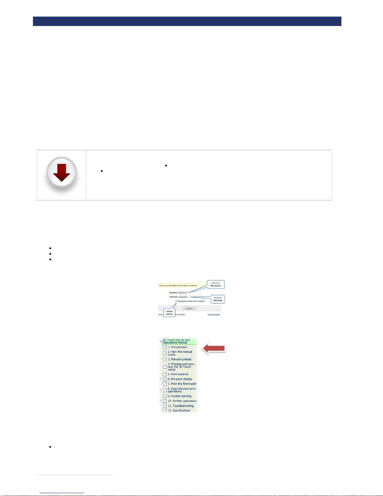
you to a log in page. Please note the details below. Simply enter:
Username: bfbcustomer
Password: 3D printing
Check the "Remember me" box
This will prevent the timeout from happening again during your session.
You can start reading the manual by clicking the links on the navigation bar at the left of the screen:
Off-line reading
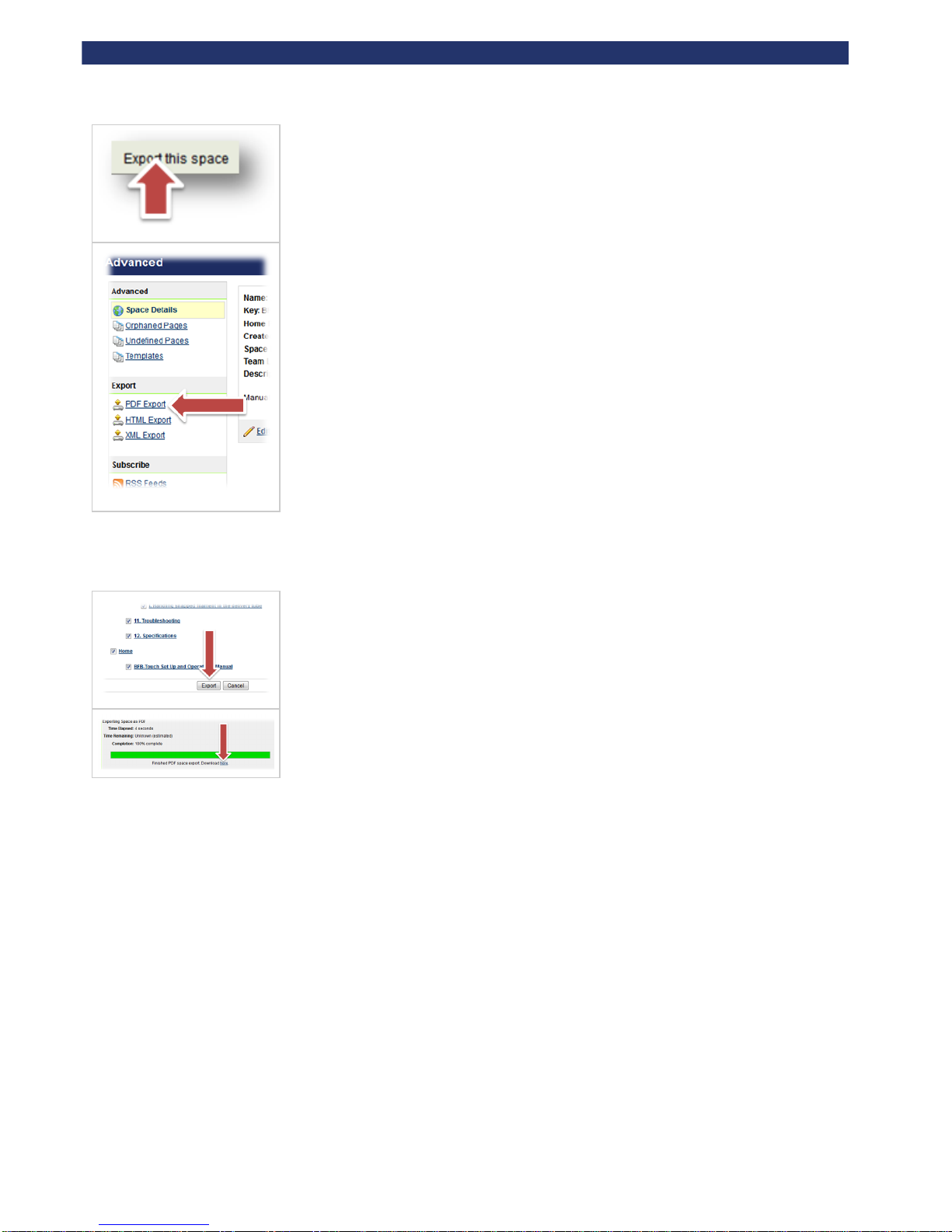
Simply click on the "Export this space" button at the top left of the screen to export the manual to a PDF. Follow the on screen instructions.
Page 4
Rapman 3.2 Operations Manual
Page 4
If you have a slow internet connection, it is possible to select individual sections of the manual to export, making it possile to download small
sections at a time. Simply tick the boxes next to the sections you need.
Alternatively, if bandwidth is not an issue, select all.
Page 5
Rapman 3.2 Operations Manual
Page 5
1. Introduction
Before first use, the RapMan needs careful setting up. The list below illustrates some of the essential operations which must be carried out before
operation:
It's very important to , especially if you have a multi-head unit.[check your firmware version]
Make sure the bed is clear of any build material
Check the bed is fitted correctly
Check the hot-end nozzles are clean from plastic debris
Check the bed is level
Check the bed is referenced to the extruder nozzles
Load the extruders correctly
Print a successful raft
Failure to carry out of the set-up procedures contained in this document will damage the machine.all
This document has been designed to illustrate the procedures and get you up and running as quickly as possible. Please take time toessential
understand how the process works and complete each procedure in the order set out in this manual.
Have a look through the and sections.Pre-print checks Further operations
First setup can take 60 minutes depending on the skill level of the operator. After that, typical set up time before a print can range from 0-5 minutes.
Support is available by raising a ticket at www.bitsfrombytes.com
We welcome any feedback you may have, and wish you well in your 3D printing!
Page 6
Rapman 3.2 Operations Manual
Page 6
2. How this manual works
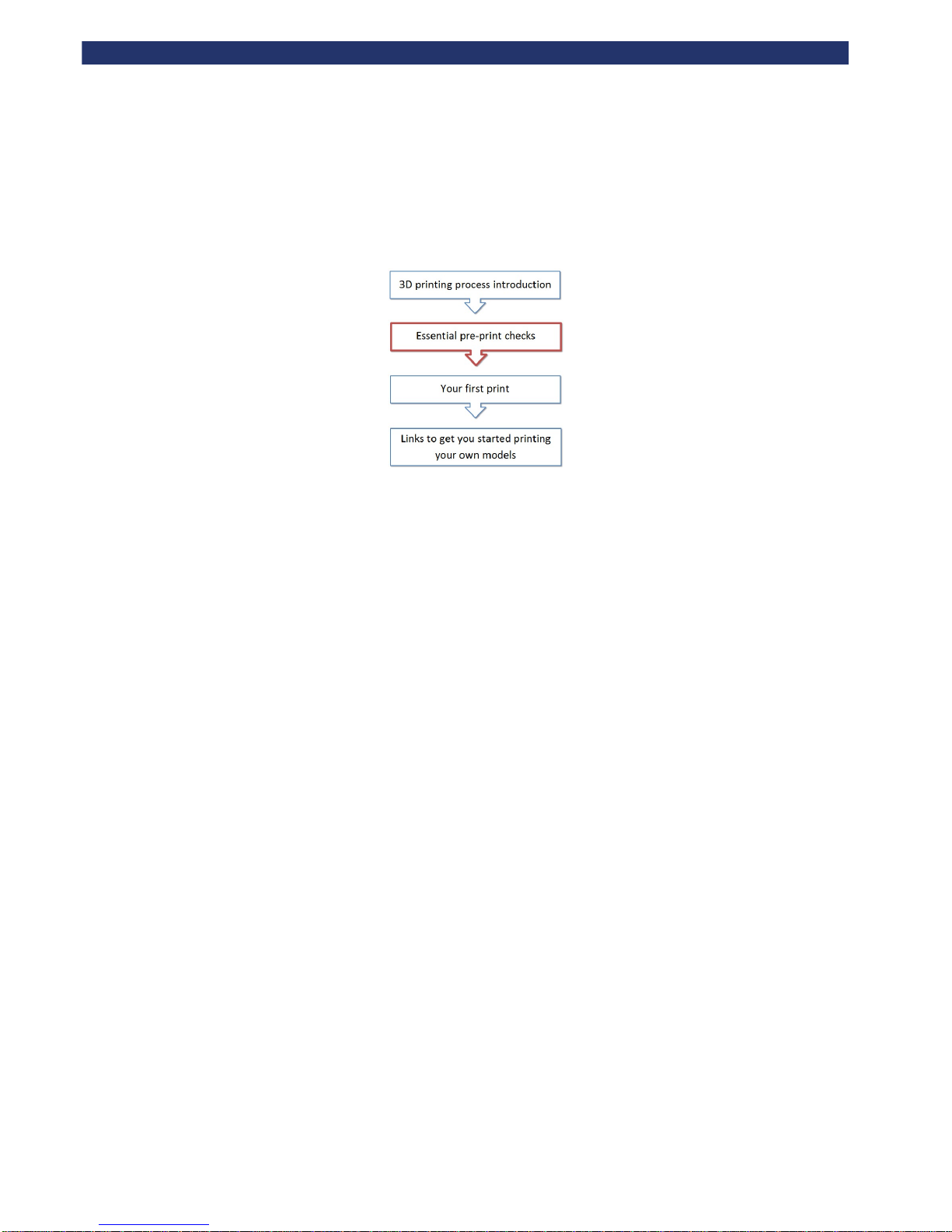
This manual leads you through the essential pre-print operations towards your first actual 3D print.
Page 7
Rapman 3.2 Operations Manual
Page 7
3. Manual symbols
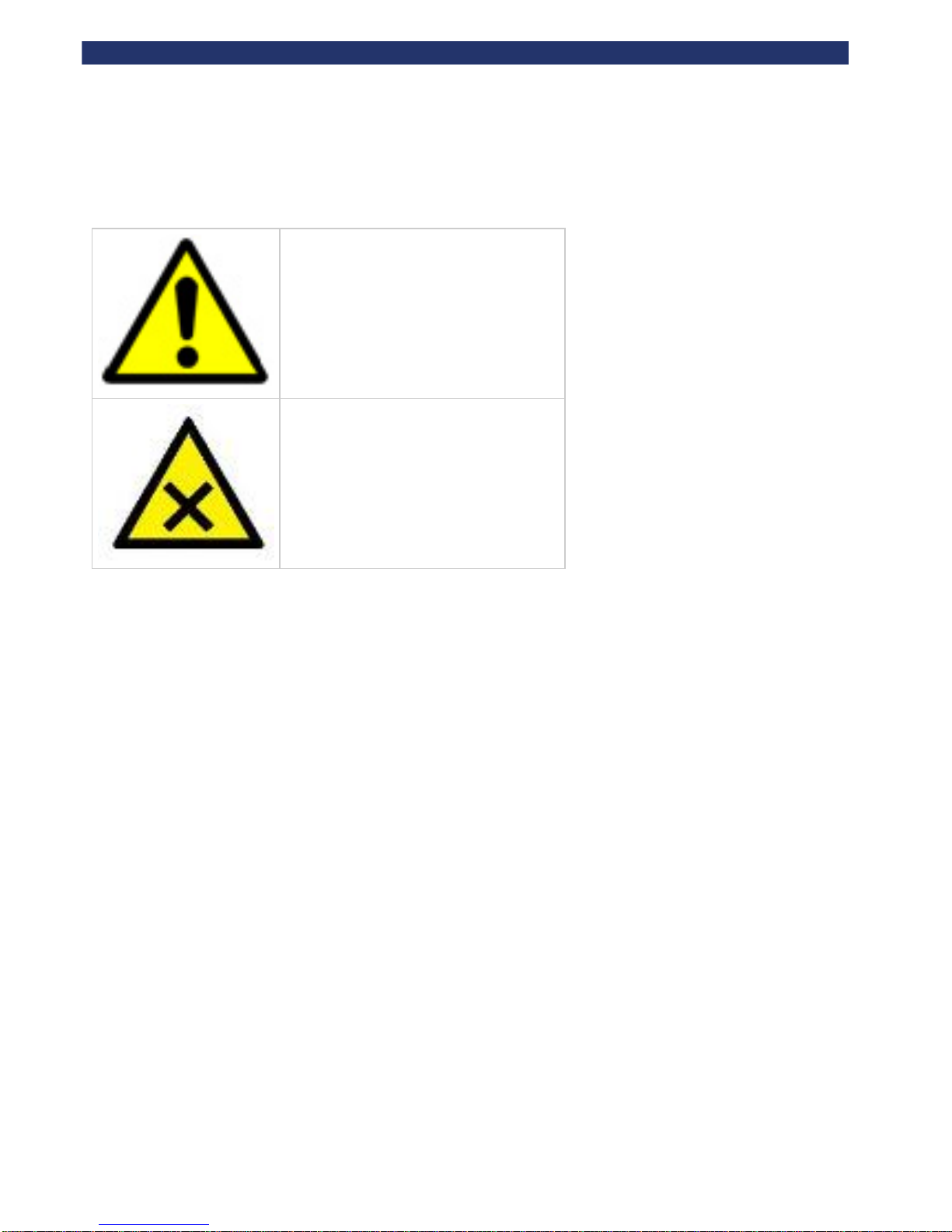
notes to prevent damage to the machine.CAUTION:
notes to prevent injury to the operator.DANGER:
Page 8
Rapman 3.2 Operations Manual
Page 8
4. Process overview... how the RapMan 3 works
This section briefly introduces how the RapMan prints.
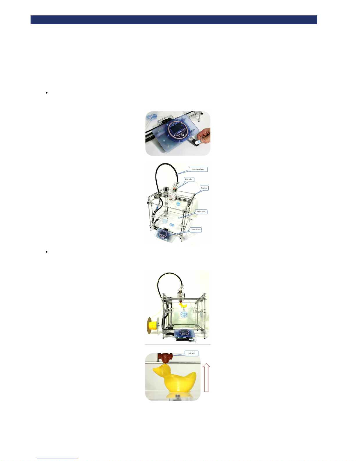
A print file from Axon (the Bits from Bytes print processing software) is transferred to the printer using a USB memory stick. To complete
- near the end of this operations manual we will prompt you toyour first set up you will not need to use Axon to generate print files
download some print files for you test your printer, after you have completed the essential setup operations.
The extruder pulls filament from the reel via the delivery tubes and drive through a hot-end to produce a thin molten filament of plastic. The
extruder draws each layer with this filament. After each layer is produced the bed increments down so that a new layer can be drawn on top
of the last, building up the 3D model.
Page 9
Rapman 3.2 Operations Manual
Page 9
1.
2.
5. Print material
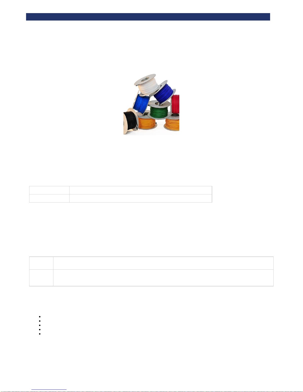
We support two print materials: PLA and ABS. Both have different properties and can be used in different build/support combinations. Typically, PLA
performs well as a build material with an ABS raft, and (if needed) ABS support.
PLA
PLA is a hard plastic with a low environmental impact. It is not a petrochemical - it is derived from renewable resources, such as starch. It is a
relatively new plastic and has excellent print characteristics.
As a build material: Good for large and small prints. Stable for 20 years up to 50 degrees Celsius
As a support material: Supports ABS well as it peels away easily. May be dissolved if required (see below).
PLA support can be dissolved by:
Leaving the model in an ultra-sonic with water and caustic soda. Time and concentration depends on the volume ofsupport removal tank
the material needed to dissolve.
Leave the model in water at 80°C for over 48 hours. The also provides this functionality.support removal tank
ABS
ABS is a well-known plastic with excellent toughness characteristics.
As a build
material:
Good for small prints with high toughness requirements. Do not print area larger than 100 mm square – ABS has relatively
high shrinkage on cooling, and some geometries for larger prints are prone to warping.
As a
support
material:
Supports PLA well as it peels away easily.
Material storage
All polymers degrade with time. The following conditions ensure the filament remains high quality:
Do not unpack until filament is needed.
Store at room temperature: 15-20 °C.
Keep away from UV light (e.g. sunlight).
If machine is to left unused for an extended period of time, repack filament with silica-gel sachet to maintain dryness (if present).
Use within 12 months of receipt.
Page 10
Rapman 3.2 Operations Manual
Page 10
6. Pre-print checks
It is that all pre-print checks are carried out before starting a print. This section of the manual guides the user through these checks:essential
a. Clearing the print bed
b. Check the print bed is fitted correctly
c. Power up
d. Test all axes
e. Check the hot-end nozzles are clean from plastic debris
f. Check the print bed is level
g. Check the bed is referenced to the extruder nozzles
h. Load the extruders
i. Extruder control
j. Purge the extruder
k. How to start a print
l. Double head calibration
m. Print a successful raft
Page 11
Rapman 3.2 Operations Manual
Page 11
a. Clearing the print bed
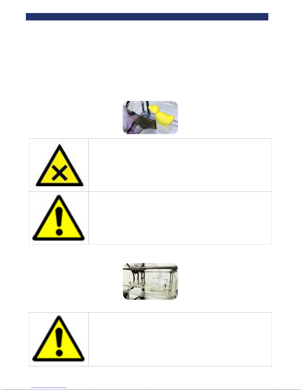
It is essential to clean the print bed before printing. This makes sure that the first printed layer makes a good contact with the bed.
Remove existing prints from the print bed
Remove any previous prints with the model removal tool. Slide the edge of the model removal tool between the bed and the first layer to remove the
entire print.
The corners of the model removal tool are sharp and can cut your hands if improperly used. Always wear
thick leather gloves or equivalent PPE. Always strike the model in a direction away from body parts. If large
forces are needed to remove the model, see the note below.
If the model is difficult to remove from the bed in situ, you can take the whole bed out of the machine to make
the removal process easier (refer to ).b. Check the print bed is fitted correctly
Check the bed is clear of any build material
Ensure that all build material is completely removed from the bed. Use the model removal tool to remove any stuck-fast tracks.
It is normal for prints to leave marks on the bed, and for the model removal tool to lightly scratch the surface
of the bed. This will not affect the printer's operation. However, take care to avoid gouging the surface with
the material removal tool - the bed needs to be flat.
Page 12

Rapman 3.2 Operations Manual
Page 12
Page 13
Rapman 3.2 Operations Manual
Page 13
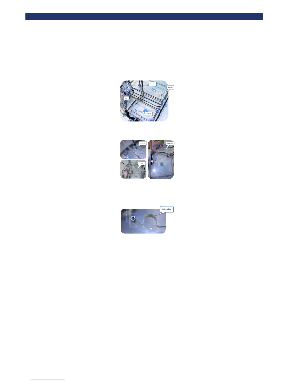
b. Check the print bed is fitted correctly
Ensure that bed is correctly fitted to the printer. The four clamping bolts should sit comfortably at the end of the corner slots. If not, remove the bed,
then refit it - as shown in the next two sections.
How to remove the bed
Correct fitting
When replacing the bed, make sure that it is fitted correctly:
Page 14
Rapman 3.2 Operations Manual
Page 14
c. Power up
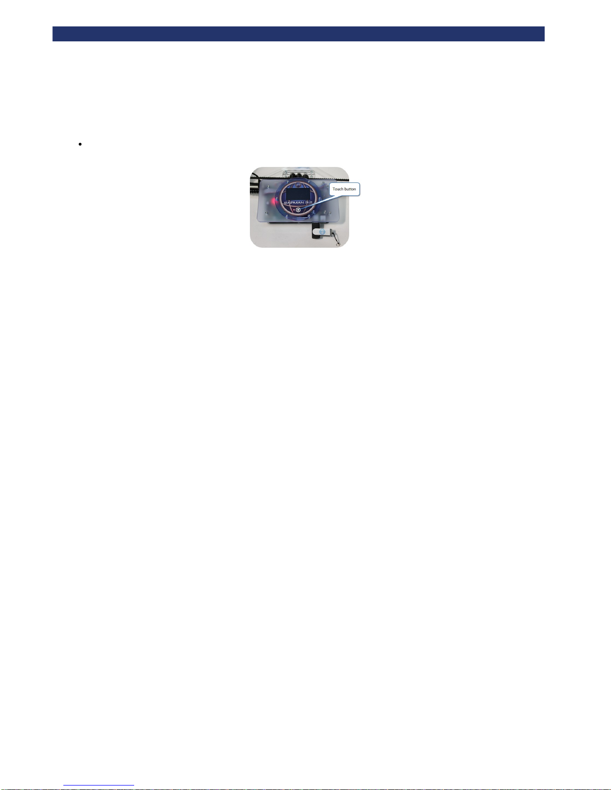
Ensure the power cable is attached, and that power is being supplied to the printer. To start the printer, press and hold the function button
for 2 seconds. This will boot the printer, activating the boot screen (the BFB logo). Touch the screen to show the home menu.
Page 15
Rapman 3.2 Operations Manual
Page 15
d. Test all axes
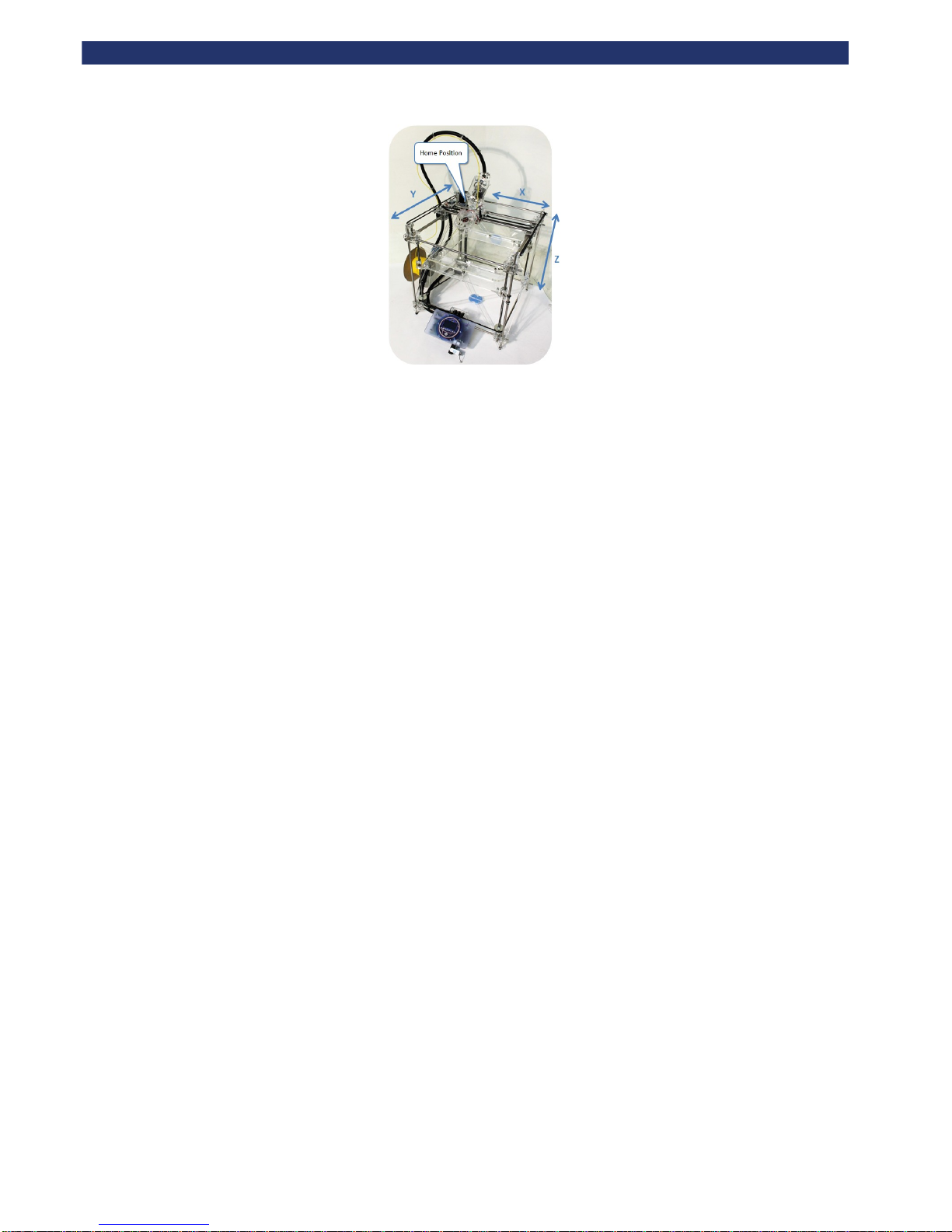
It is important to check that the print head can move freely in all 3 axes: X, Y and Z. First power up the printer, then use the manual move function to
move the print head in all three axes:
Get familiar with moving the axes around:
Ensure that the bed is fitted properly to the machine (see ).b. Check the print bed is fitted correctly
After powering up select the 'Manual move' function:
Use X, Y and Z buttons to move each axis respectively.
Caution: Always move the Z axis first to ensure that bed is away from the extruder nozzles, and does not
collide during an X/Y move. Collisions between the extruder nozzles and the bed may damage both.
Caution: Observe each X/Y axis movement. In these axes, it is possible to drive the extruders too far away
from the "Home" position (shown in the picture below) into the printer frame. Avoid this. Excessive collisions
will damage the printer.
Caution: Observe each Z axis movement. In this axis, it is possible to drive the bed too high (into the extruder
nozzles) or too low (into the motor coupling). Avoid this. Excessive collisions will damage the printer.
After confirming movement for all axes, press the function button to return to the main menu.
Page 16
Rapman 3.2 Operations Manual
Page 16
Page 17
Rapman 3.2 Operations Manual
Page 17
e. Check the hot-end nozzles are clean from plastic debris
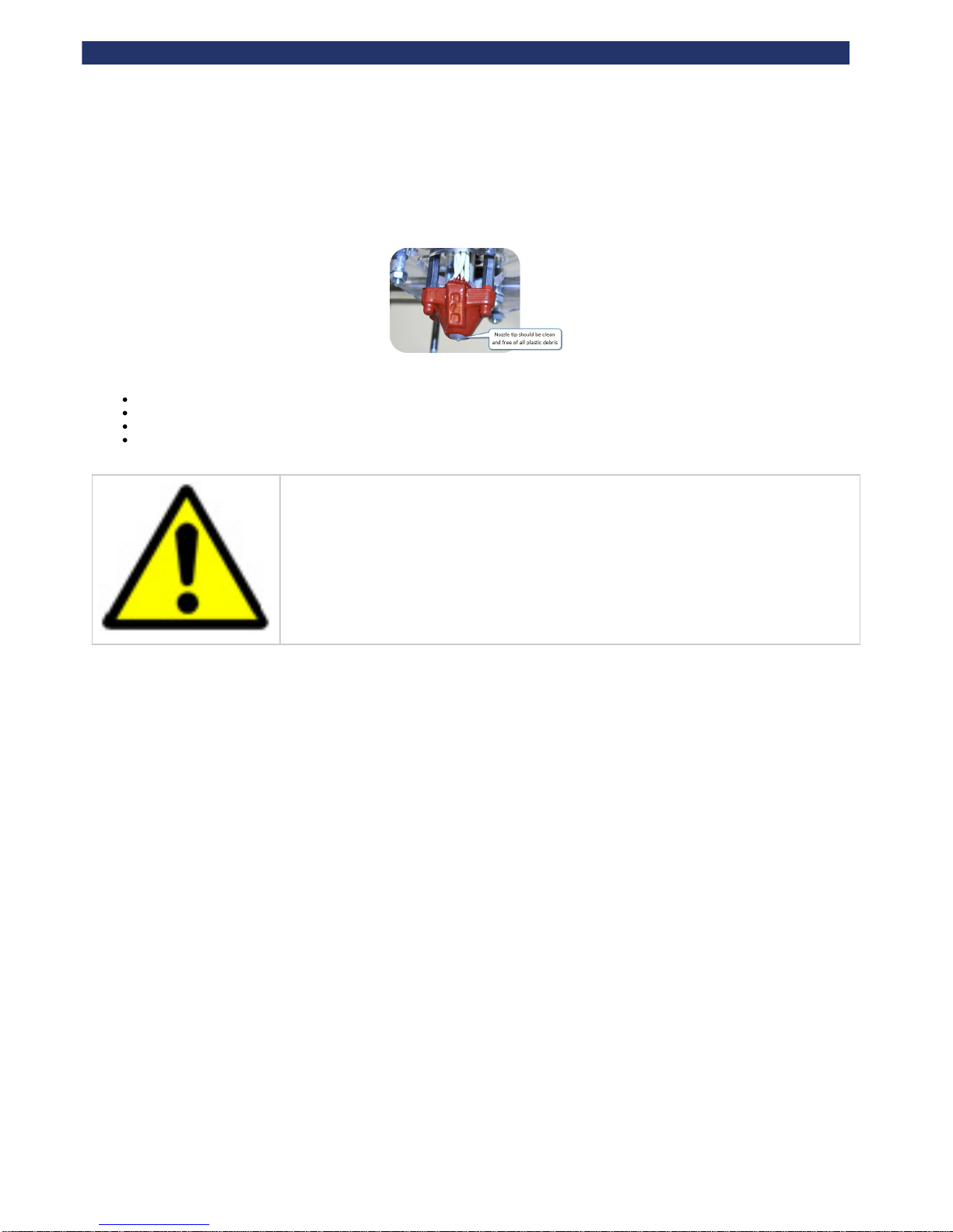
Ensure that the metal nozzle tips are clean from any plastic debris. All tips should be clearly visible.
If not:
Lower the bed to make access to the nozzles easy.
Position the extruders in approximately the middle of the machine (see ), to make access to the nozzles easy.d. Test all axes
Pull away any light plastic debris away from the nozzle tip using the pliers.
If plastic debris is stubborn, you may need to heat the extruder to make the plastic soft enough to remove. To heat the extruder up, please
refer to .i. Extruder control
Caution: When heating up nozzles to remove plastic debris, the nozzle tips with your fingers.do not touch
Extruders will burn if touched when hot.
Page 18
Rapman 3.2 Operations Manual
Page 18
f. Check the print bed is level
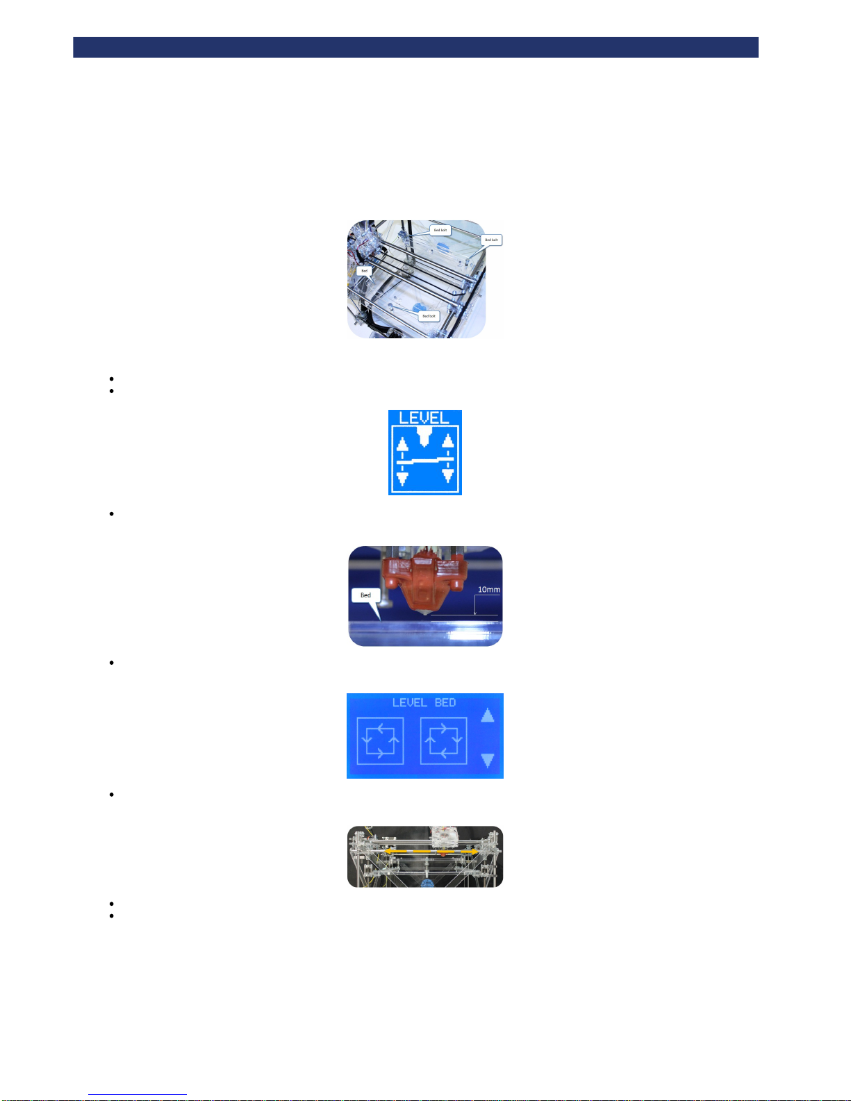
To get a good print, the bed must be level. The print bed is mounted on three sprung bolts which allow adjustment of the bed height in three places.
The 'Level Bed' function moves the extruder carriage around the corners of the bed so the operator can adjust the bed bolts to achieve a level bed.
Check the bed is fitted correctly.
On the touch screen select ‘Level Bed’ function:
Use the Up and Down arrows to raise and lower the bed to adjust the gap between the hot end and bed. Start with approximately 10 mm
distance between the nozzle and the bed. This will enable rough levelling.
Touch the ‘Clockwise’ and ‘Anti-clockwise’ buttons to automatically move the carriage around the corners of the print bed (view on-screen
instructions for more movement options):
During each movement along the side of the bed, observe from the side of the machine any change in distance between the bed and
extruder's hot-end as it moves along.
Adjust the height of the bed bolts to make each side level using a 13mm spanner.
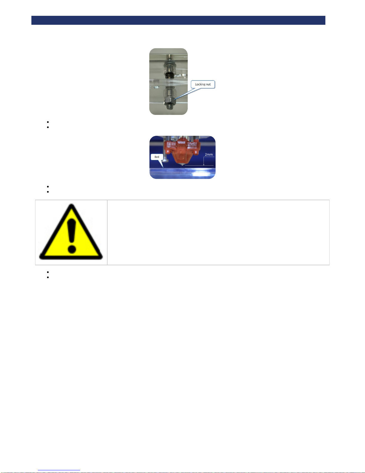
Underneath each of the 3 bed bolts is a locking nut which must be loosened with the 13mm spanner before the bolt can be adjusted.
Page 19
Rapman 3.2 Operations Manual
Page 19
It may take several movements of the extruder, and consequent bolt adjustments to ensure that the bed is level.
Ensure that axes are checked from the appropriate side of the machine (to better judge flatness):
Use the Up and Down arrows to reduce the gap between the hot end and bed to approximately 2 mm. This will enable finer levelling.
Repeat the levelling process.
Caution: Observe each extruder movement. The nozzle should not touch the bed. Moving the extruder with
the nozzle touching the bed will damage the nozzle and the bed. If the nozzle touches the bed, immediately
lower the bed using ‘down arrow’ icon.
Press the Function button to leave the ‘Level Bed’ menu, and return to the main menu.
Remember to lock the 3 bed bolts in position by tightening the lock nut under each, using the 13mm spanner. Tighten lightly - the acrylic
thread may strip with excessive torque. Whilst tightening the nut, make sure that the bolt does not spin by holding it in position with the
13mm spanner, from the top side of the bed.
Page 20
Rapman 3.2 Operations Manual
Page 20
g. Check the bed is referenced to the extruder nozzles
After levelling the bed, the nozzles must be set to the correct height, to ensure that the first printed layer sticks properly (if the nozzle is too high the
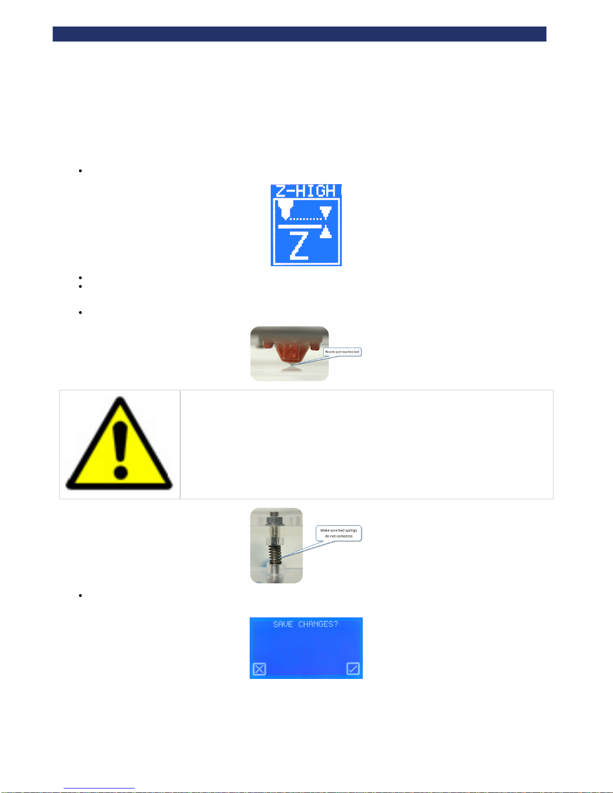
filament will not stick to the bed, if the nozzle is too low the bed may block the nozzle). Use the 'Set Z Height' function to accurately adjust the height
of the nozzle for the first layer.
On the touch screen select ‘Z-High’ function:
Observe the gap between the nozzle and bed from the front of the machine. Press and hold the Z+/- buttons to move the bed.
Start with a gap between the bed and the nozzle. Move the bed towards the nozzle. Observe the bed as it approaches the nozzle. Stop
raising the bed as soon as the nozzle touches the surface of the bed. If the bed goes too far, simply move the bed back and repeat the
approach.
The bed should just touch the nozzle, without any compression in the bed springs:
Caution: If the nozzle is pushed too hard against the bed, the nozzle will be forced into the bed for the whole
first layer of printing. This will damage the nozzle and the bed. Ensure that setting the nozzle against the bed
does .not compress the bed springs
Pressing the Function button gives the option to save the setting to the printer’s memory, which is retained when the power is turned off.
The Z offset value will be applied for each subsequent print.
Page 21
Rapman 3.2 Operations Manual
Page 21
h. Load the extruders
If you have a double head RapMan, and this is your first setup you will need to which requires PLA in both heads, soNOTE: calibrate the heads
follow the steps below but using PLA in both heads until you have completed the head calibration.
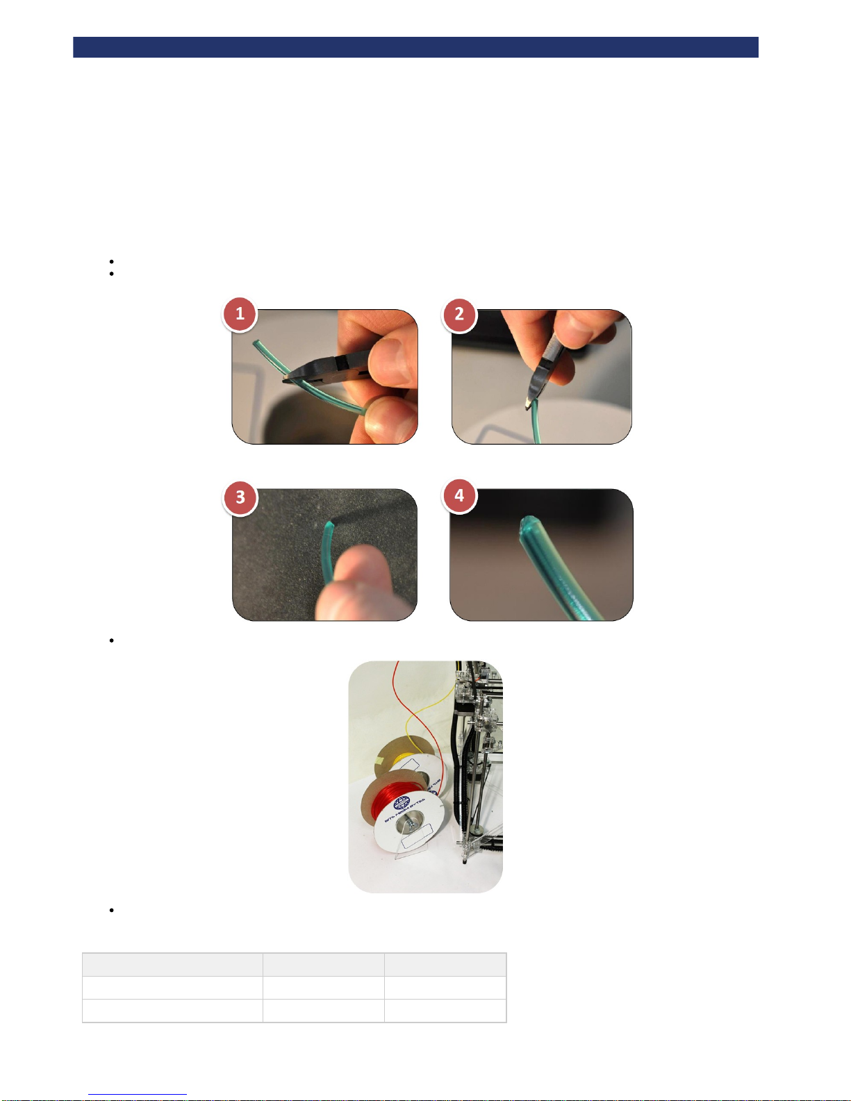
Before loading a reel, the end of the filament must be prepared to prevent damage to the delivery tubes. This procedure is to prevent anyessential
damage to the delivery tubes, which may in turn block a nozzle.
Cut the end of the filament at 45° from both sides to produce a point using side cutters.
Remove all sharp edges. The tip should feel smooth.
Position the reels below (photo is for double head printer, therefore two reels are shown. For a single head printer, only one reel is needed).
Load the type of materials into their reel positions according to the number of extruders in the printer:
Number of extruders in the printer Material for Extruder 1 Material for Extruder 2
1
ABS or PLA
2
ABS PLA
Page 22
Rapman 3.2 Operations Manual
Page 22
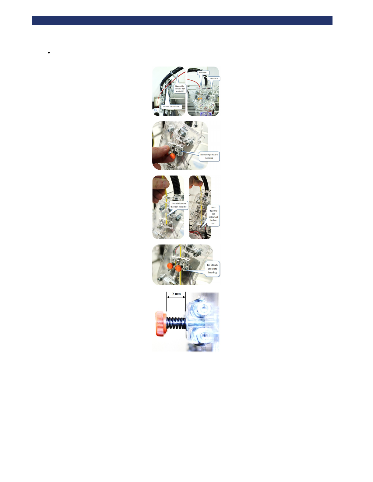
After positioning the reels, feed the filaments through the appropriate holes along the conduit, making sure the filaments exit the tubes at
the correct extruders:
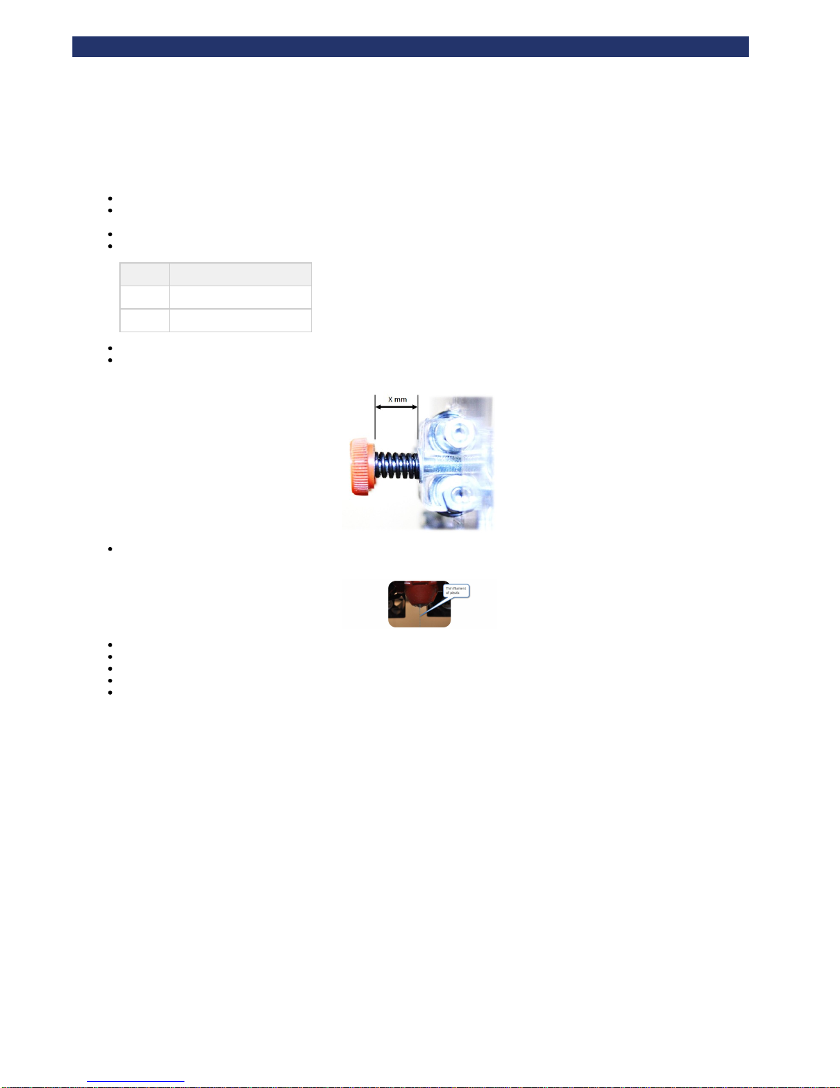
See to refine the spring compression on the pressure bearing (nominally 12mm).c. Setting the extruder pressure bearings
Page 23
Rapman 3.2 Operations Manual
Page 23
i. Extruder control
Make sure all extruders are loaded.
Use 'Manual move' (see ) to move the extruders to the centre of the machine, and lower the bed. This makes it easy to cleand. Test all axes
any purged material.
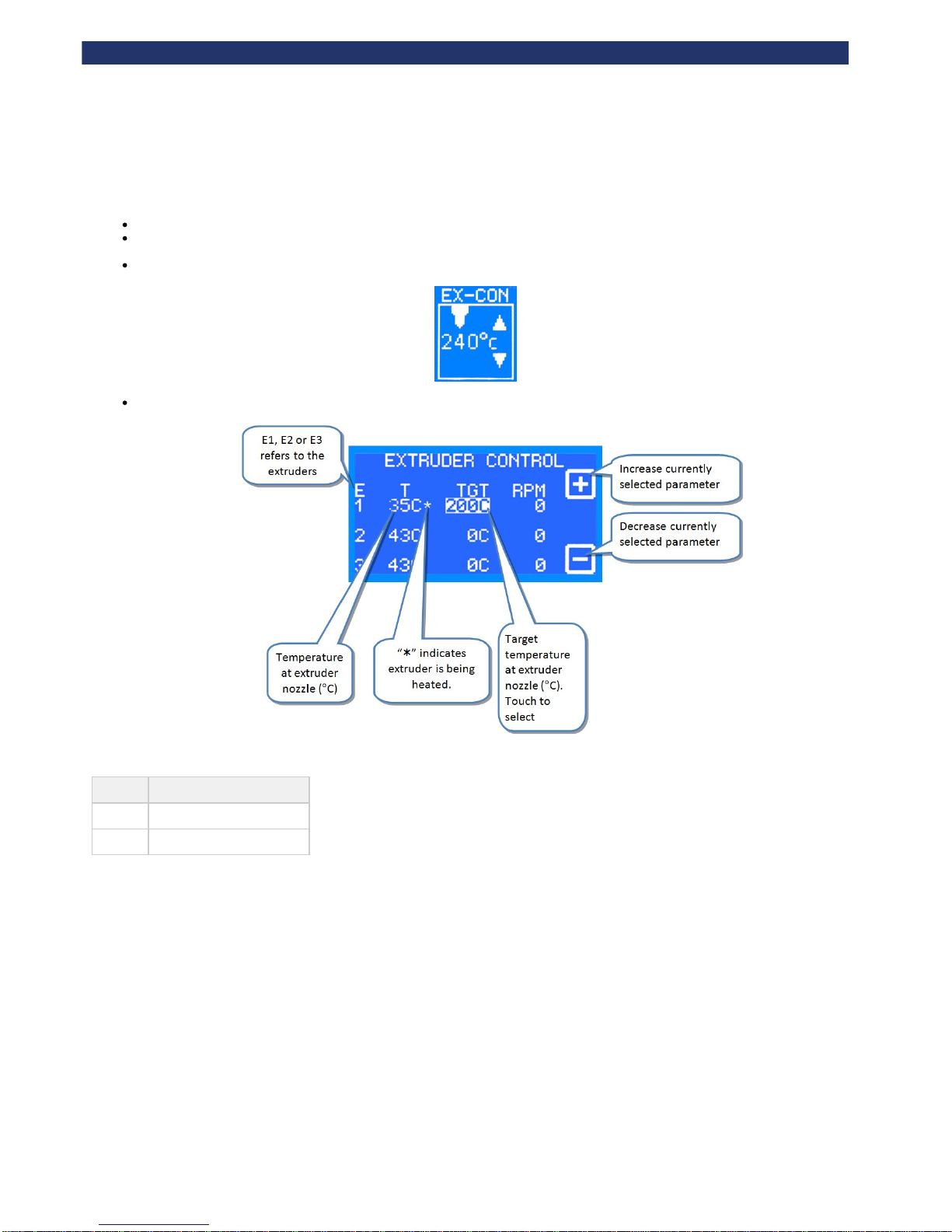
On the control panel select the ‘Extruder control’ function
'Extruder control' manages one extruder at a time (E1, E2 or E3) using the buttons on the control panel.
Recommended maximum extrusion temperatures for materials:
Material Extrusion temperature (°C)
ABS
260
PLA
195
Note: Extruders share power, therefore an extruder will heat up quicker if it is the only extruder with a high target temperature.
Page 24
Rapman 3.2 Operations Manual
Page 24
j. Purge the extruder
Ensure filaments are loaded into the extruders, as defined in the .h. Load the extruders
Make sure the springs on the extruder pressure bearings are compressed (as detailed in ) enoughc. Setting the extruder pressure bearings
to push the filament into the teeth of the drive shaft.
Proceed by purging one extruder at a time.
Heat the extruder (as shown in ) to the maximum temperature defined below, depending on the material in the extruder: i. Extruder control
Material Extrusion temperature (°C)
ABS
260
PLA
195
Once the target temperature has been achieved, turn the RPM up to 30.
Examine the movement of the filament at the pressure bearing. It should slowly be driven towards the nozzle. If not, ensure that the spring
pressure bearing is compressed sufficiently ( ).c. Setting the extruder pressure bearings
Observe the end of the nozzle. A thin bead of molten plastic should come out of the nozzle. Depending on how far the filament was loaded
into the extruder, this could take several minutes.
Allow material to purge for a few seconds before reducing the RPM to 0.
Repeat the purge process for each extruder.
Turn the machine off to allow the nozzles to cool.
As the extruders cool, clean the nozzles (see "Check the hot-end nozzles are clean").
Dispose of all waste filament from the nozzle.
Page 25
Rapman 3.2 Operations Manual
Page 25
k. How to start a print
Before starting any print, make sure that the all have been completed.pre-print checks
The following sections will ask you to run two test files: a raft check file, and a duck. When asked to print a file you will need to follow the procedure
below:
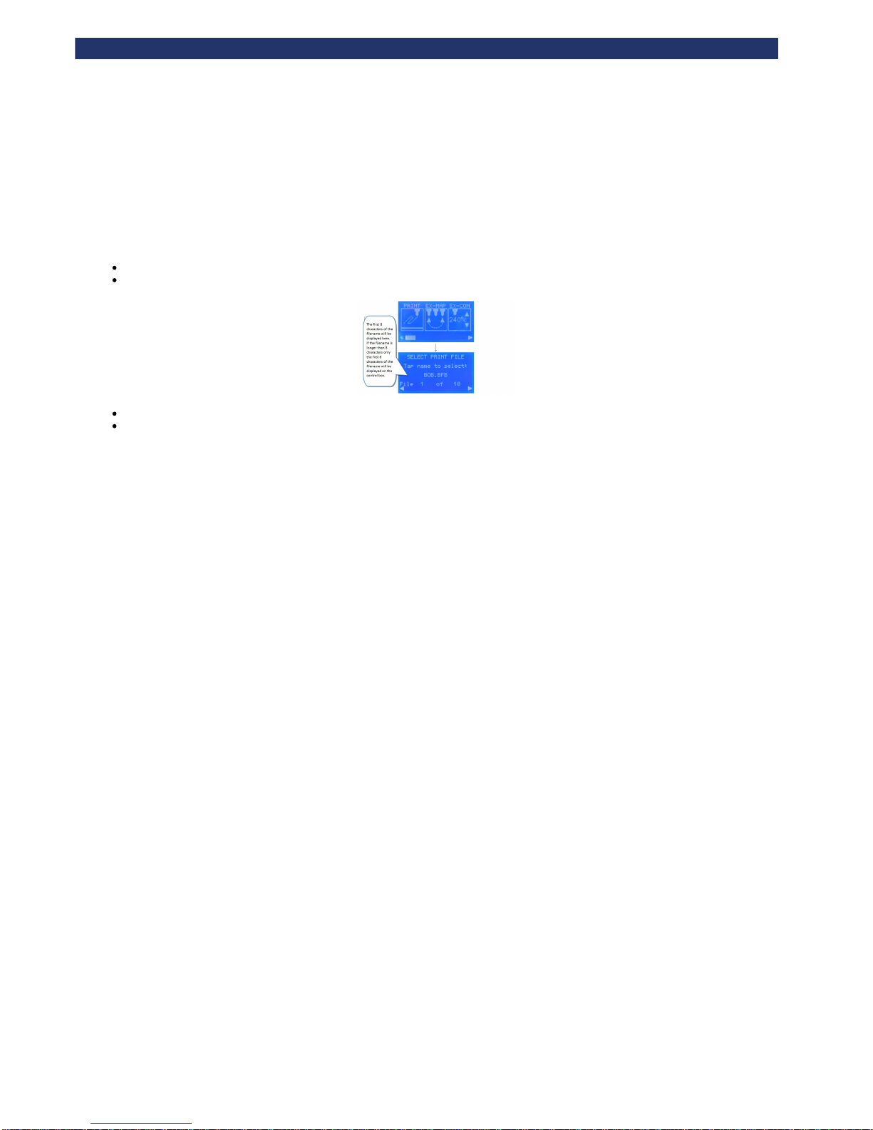
Insert the memory stick into the USB slot.
Select the “Print” icon:
Select the correct print file using the left and right arrow keys.
Touch the name of the print file to start the print.
The following sections will dictate which files print.
Page 26

Rapman 3.2 Operations Manual
Page 26
l. Double head calibration
You only need to read this section if you have a double head RapMan.
If you have a double head RapMan, and this is your first setup you will need to calibrate the heads. Once this is complete you will not need to
calibrate the heads again.
Please complete the . Multiple print head XY calibration manual Note: this will redirect you to a different, separate manual. Please
return to this operations manual after completion. To aid navigation, we recommend opening the calibration manual in a new tab
(simply hold down the 'Ctrl' key when clicking the link).
Page 27
Rapman 3.2 Operations Manual
Page 27
m. Print a successful raft
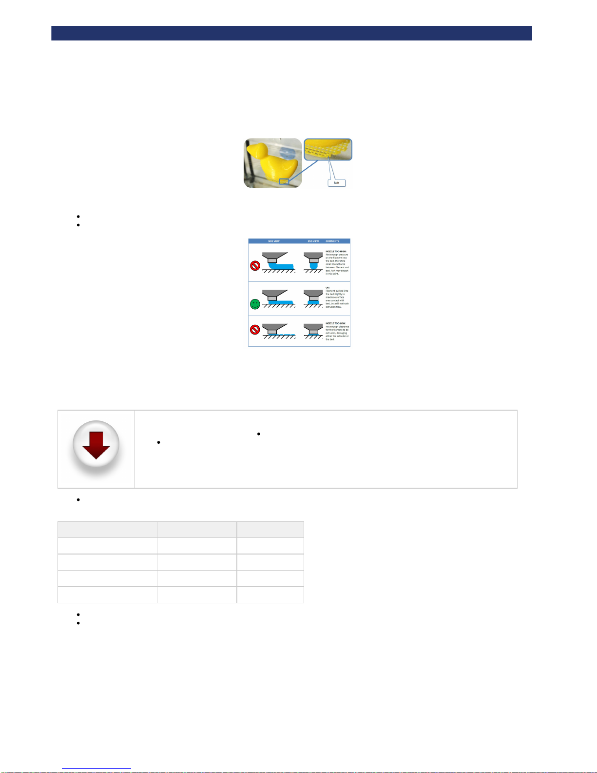
It is essential that a good raft is printed to guarantee a good build. Therefore the height of the hot-end nozzle over the bed for the first layer is critical:
If the nozzle is too far away from the bed, the filament will not stick to the bed
If the nozzle is too low it will not be able to extruder the filament, and there is a risk of damage to the bed and the nozzle.
Print the raft check file
If this is your first time printing, you may wish to print the raft check file (if you have not already downloaded the zip file containing test print files, you
can do so using the link below).
To download the files click the icon on the left. After downloading:
Unpack the files to the root of your USB stick.
The printer can only see uncompressed files at the root of the USB stick i.e. do not put them inside a folder.
Follow the section to print the preloaded raft check file relevant to the material loaded into Extruder 1 (see table below).How to start a print
Remember, only the first 6 characters of the filename will be displayed on the control box if the filename is longer than 8 characters.
Material type in Extruder 1 Number of extruders File to print
ABS
1 RaftA1rapman.bfb
ABS
2 RaftA2rapman.bfb
PLA
1 RaftB1rapman.bfb
PLA
2 RaftB2rapman.bfb
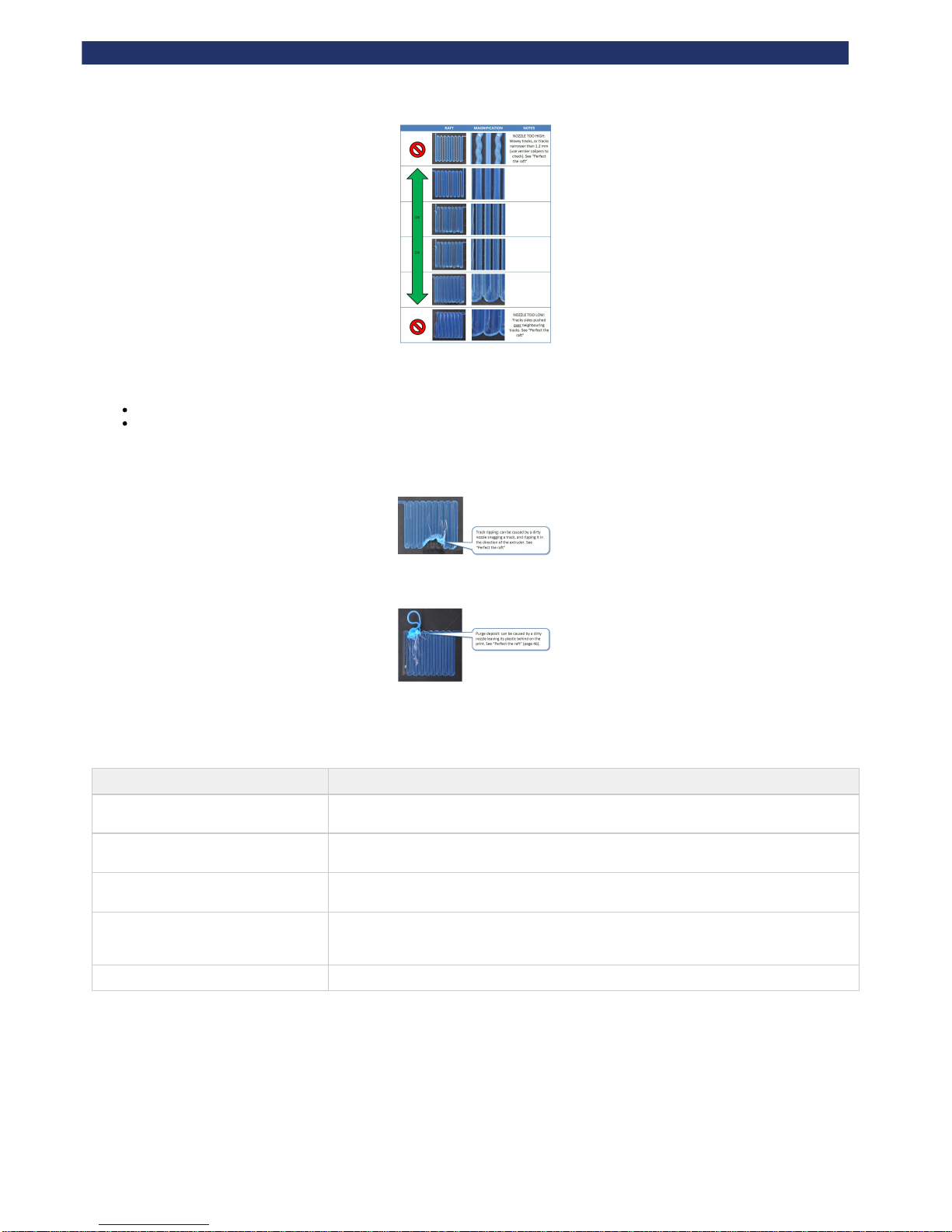
Examine each raft pad in the check file, as guided in the following section.
Remove the raft print when complete using the model removal tool (see ).Clearing the print bed
Examine the raft check file
Page 28
Rapman 3.2 Operations Manual
Page 28
Potential problems
If the raft pad appears damaged, match the imperfection to the two scenarios below, and follow the corrective action suggested.
Note that there may be some imperfections in the raft, but that the process is very forgiving and even the images shown below will generally
not spoil a full print.
Track ripping
Purge deposit
Perfect the raft
If analysis of the raft check file yields any problems, you will need to re-examine some of the setup stages:
ERROR CORRECTIVE ACTION
Nozzle too high
See to adjust the height at which the nozzleg. Check the bed is referenced to the extruder nozzles
starts printing.
Nozzle to low
See to adjust the height at which the nozzleg. Check the bed is referenced to the extruder nozzles
starts printing.
Nozzle heights appear inconsistent
across a single print
Check the print bed is level
Track ripping
, orCheck the hot-end nozzles are clean from plastic debris
(links to multiple head calibration manual) if the trailing head is lower than theLevel the heads
printing head, it will rip up the printed tracks.
Purge deposit
Check the hot-end nozzles are clean from plastic debris
Page 29
Rapman 3.2 Operations Manual
Page 29
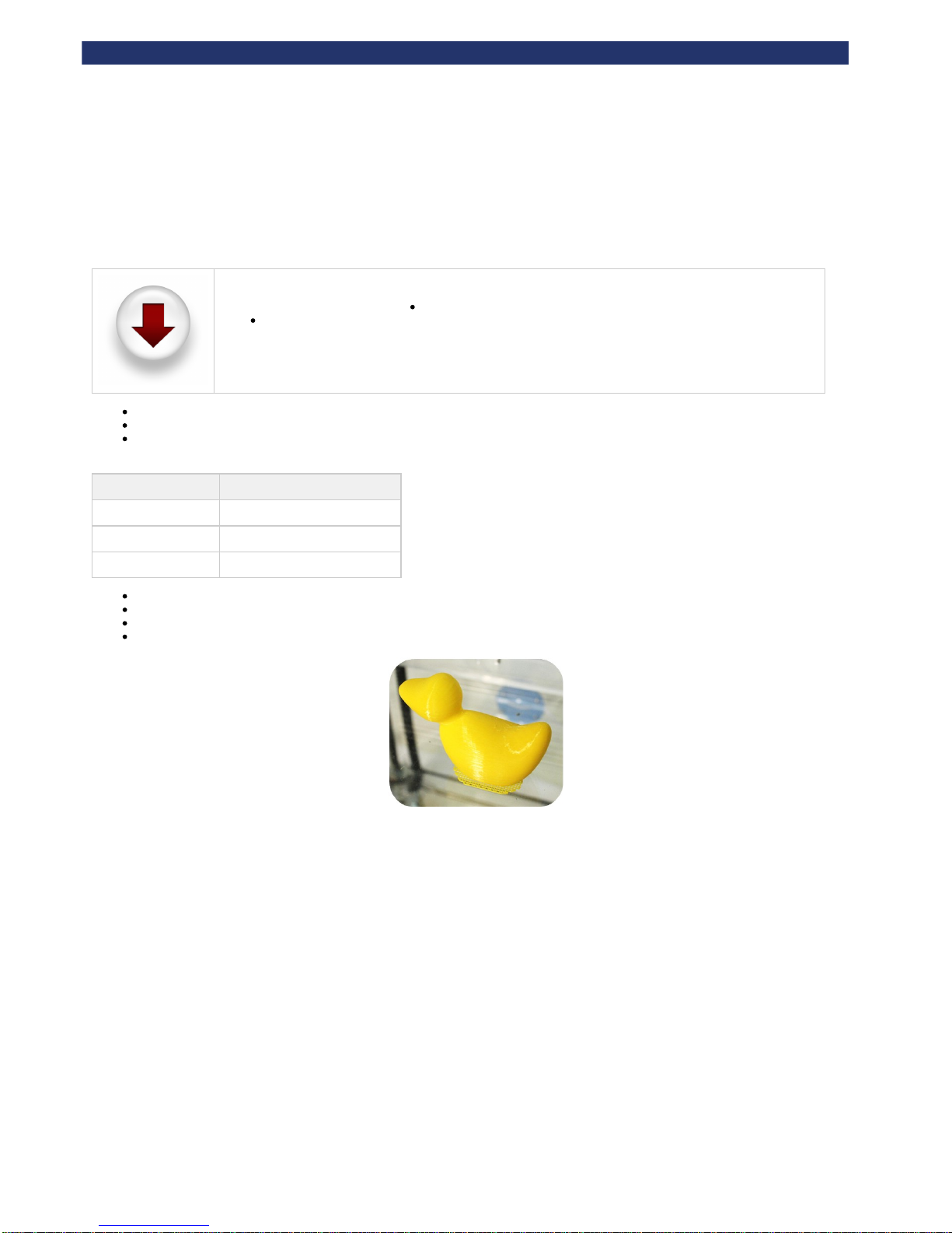
7. Print the first model
To get your RapMan printer up and running as quickly as possible, we have included a duck in the test print files (if you have not already
downloaded the zip file, you can do so by clicking the link below).
To download the files click the icon on the left. After downloading:
Unpack the files to the root of your USB stick.
The printer can only see uncompressed files at the root of the USB stick i.e. do not put them inside a folder.
Make sure all are complete.pre-print checks
Make sure materials are loaded in the order defined in the (this is important as the print files assume this setup).Load the extruders
Follow the directions to print the Duck file from the memory stick. The Duck file you must choose is determined by theHow to start a print
number of extruders on your printer (see table below).
Number of extruders File name
1 (ABS)
Duck1A_E1_ABS.bfb
1 (PLA)
Duck1P_E1_PLA.bfb
2
Duck2_E1_ABSraft_E2_PLA.bfb
After printing, follow the procedure detailed in to remove the model from the printer.Clearing the bed
Carry out essential post-print operations (detailed in the next section).
Remove the raft from the model with sandpaper.
For tips on post-processing your model, check out our .on-line FAQ
Page 30

Rapman 3.2 Operations Manual
Page 30
8. Essential post-print operations
After a print you must remove the printed model using the model removal tool.
a. Print removal and post-processing
Page 31
Rapman 3.2 Operations Manual
Page 31
a. Print removal and post-processing
This section covers the following post-processing questions:
How do I get the finished part off the print bed?
I can't get the finished part off the bed
The part has left marks on the bed, what can I do about it?
How do I remove the raft from the model?
Is it safe to paint the part when it is finished?
How can I smooth the part when it is finished?
If I have support material on my part how do I remove it?
Break-away
Dissolvable support material
How do I get the finished part off the print bed?
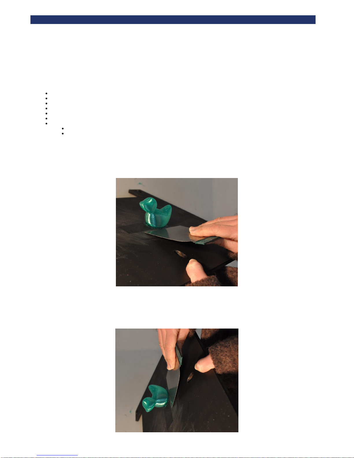
Use the scaper tool. Slide it along the bed toawrds the model so that it strikes the bottom of the raft. A few strikes should be enough to remove the
model (complete with its raft), though this varies depending on the geometry of the model. The bed must be totally clear of plastic debris before the
next print.
(3D Touch bed shown here)
I can't get the finished part off the bed
If the part is stubborn to come of the bed, it is much easier to deal with removal by taking the print surface out of the machine, and striking the raft
from a downward angle.
(3D Touch bed shown here)
Page 32
Rapman 3.2 Operations Manual
Page 32
If a part is very difficult to remove, persist with the scraper. Tough removal is because the nozzle was referenced at an incorrect height to the nozzle
- i.e. it was too low when it started printing the first layer. Refer to the manual to ensure that the nozzle is correctly referenced before the next print.
The part has left marks on the bed, what can I do about it?
Leaving marks on the print bed is normal, and will not affect the quality of your next print.
How do I remove the raft from the model?
We recommend printing with dissimilar materials so that the part can be easily removed from its raft (e.g. PLA onto an ABS raft).
If the same material is used for both model and raft, wear safety gloves and use a craft knife to cut the excess raft away from the model. Then sand
the base of the model on a flat surface until the raft is suitably removed.
Is it safe to paint the part when it is finished?
Yes. You may find a primer level helps the paint stick, and smoothes out the parts slightly.
How can I smooth the part when it is finished?
You can sand all plastic parts. This will make the part smoother, but may change the aesthetic properties, due to micro-fatiguing mechanics e.g.
colour change.
Application of (MEK), either by dipping or lightly painting, will smooth an ABS (not PLA) layered surface. Appropriate safetymethyl ethyl ketone
precautions according to the manufacturer be followed when using this chemical.must
If I have support material on my part how do I remove it?
Support material can be removed two ways:
Break-away
If the support material is the same as the build material, support material will need to be scraped away using a knife.
If using a knife, always wear leather gloves to prevent injury to hands.
Dissolvable support material
If the support material is PLA it can be disolved. For more detail on this, please refer to section 5. Print material
Page 33
Rapman 3.2 Operations Manual
Page 33
9. Further operations
This section includes further operations and maintenance procedures:
a. Power down
b. Reloading the extruders
c. Setting the extruder pressure bearings
d. Control panel functions
e. Upgrading your printer firmware
f. Handling a ground-out filament
Page 34
Rapman 3.2 Operations Manual
Page 34
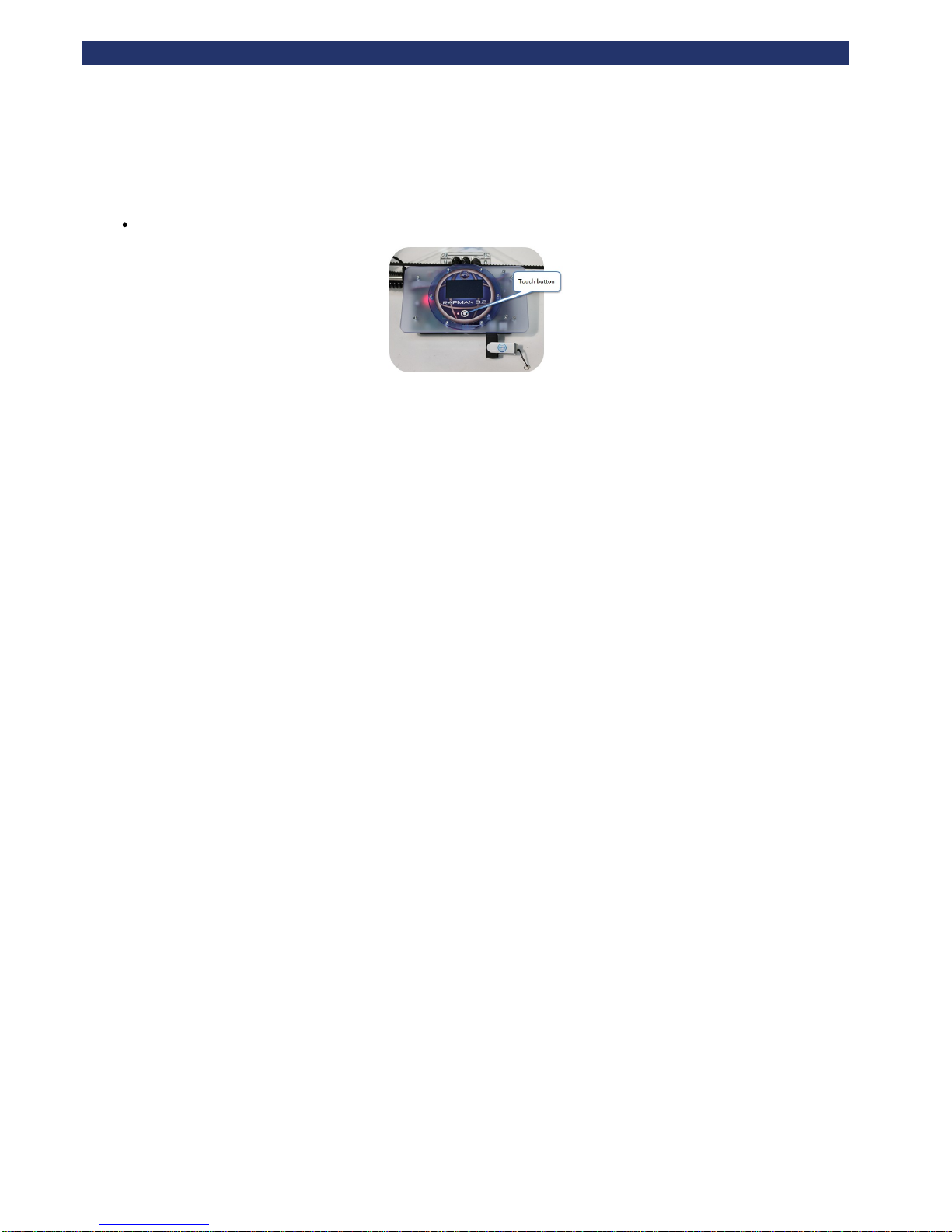
a. Power down
To turn off, hold the function button for 2 seconds when the main menu is showing.
Page 35
Rapman 3.2 Operations Manual
Page 35
b. Reloading the extruders
See for all references:Load the extruders
Remove pressure bearing.
Heat up the nozzle to extrusion temperature (see Extruder control).
Pull remaining filament out of extruder using pliers.
After removing the remaining filament, follow the instructions inthe "Load the extruders" section to load a new filament.
Purge the extruder until the old material is completely flushed out. See caution note below about purge temperature:
If a new material is being loaded in to the extruder, purge at the temperature of the material which has the
highest melting point. E.g. if PLA is being loaded into an extruder which previously had ABS, purge at 260 °C.
This ensures that the old, higher melting point, material will melt and fully flush out. Failure to do this will
result in a blocked nozzle, as the higher melting point material will remain solidified in the nozzle.
Page 36
Rapman 3.2 Operations Manual
Page 36
c. Setting the extruder pressure bearings
The pressure bearing pushes the filament into the extruder drive shaft. In turn, the drive shaft pushes the filament through the hot-end.
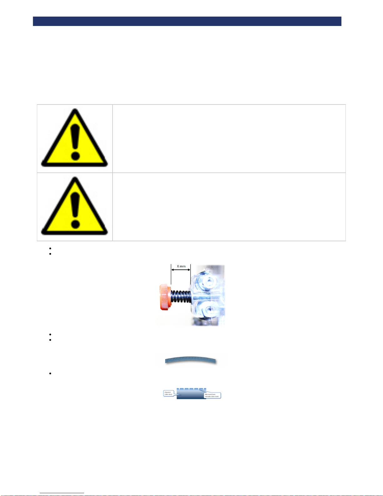
The pressure bearing setting is critical to the extrusion process during a print. It is essential to test this setting when first using the printer.
Over-tightening the pressure bearing will over-deform the filament and it will jam in the nozzle tube.
Under-tightening the pressure bearing will not engage the filament with the extruder drive shaft, therefore the
filament will not be driven through the nozzle.
Prepare the extruder for a purge as detailed in .Purge the extruder
Set the spring compression on the pressure bearing to 12mm, as shown below:
Purge the extruder at 60 RPM for 10 minutes.
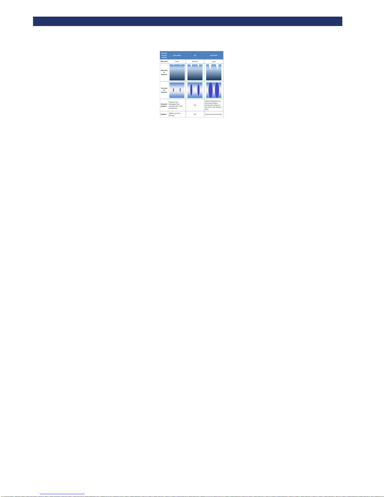
Now pull out the filament from the nozzle and examine the bite marks left on the filament from the extruder drive shaft. Compare this with
the chart below.
Once the correct pressure bearing setting is established it should be used for each print (this procedure does not need to be repeated
before each print).
Page 37
Rapman 3.2 Operations Manual
Page 37
Page 38
Rapman 3.2 Operations Manual
Page 38
d. Control panel functions
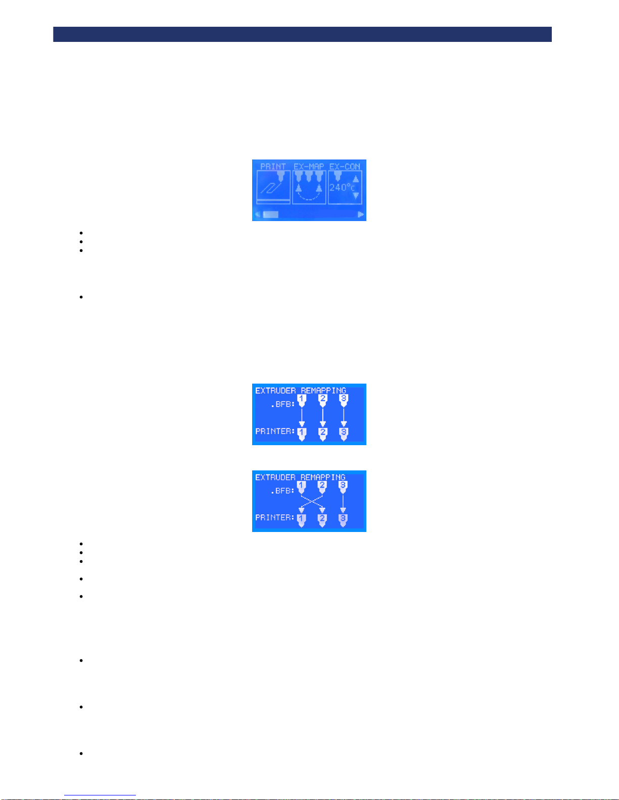
After turning the printer on, the control panel presents the main menu (below). The following sections describe all the functions.
Use the left and right arrow buttons to scroll through the menu.
Touch an icon to enter a menu.
Press the function button to return to the main menu.
Run file
See .Start a print
Extruder mapping
The extruder remapping menu allows users to reassign extruders between the .BFB file and the physical printer. This makes it possible to switch
materials after compiling the .BFB file without having to physically change the materials over.
For example, a part compiled in Axon could use two materials: ABS for the raft in Extruder 1 and PLA for the part in Extruder 2. However, the printer
is set-up with PLA in Extruder 1 and ABS in Extruder 2. The image below shows the standard mapping for the extruders.
Here the extruders are remapped so that the .BFB file Ex1 is assigned to Printer Ex2 and .BFB file Ex2 to Printer Ex1:
Use the Y buttons to change the mapping.
Press X+ to save, or Escape to quit without saving.
The user is notified prior to printing that extruder remapping is enabled as the remapping can result in unexpected behaviour if the user is
unaware of the active remapping function.
The remapping configuration settings are not stored persistently as this is deemed undesirable. When the printer power is turned on the
remapping reverts to 1:1 direct mapping. (The aforementioned pre-print remapping prompt is not shown when the mapping is 1:1)
Please ensure the Gcode file allows enough room between the left of the print and the printer framework. I.e. attempting to print the test raft
Gcode file with a double extruder RapMan will cause the extruder carriage to hit the framework when it attempts to position physical
extruder 2 into the far left corners of the print bed as the raft Gcode file instructs.
Manual move
See .Manual move
Extruder control
See .Extruder control
Home tool head
Push 'Enter' to move all axes to their home position.
Page 39
Rapman 3.2 Operations Manual
Page 39
Make sure the bed is in position before homing the tool head. The bed contains a sensor necessary for
homing. Without the sensor, the machine will drive the bed frame into the waste disposal stand-offs.
Repeated collisions will damage the machine.
Extruder offsets
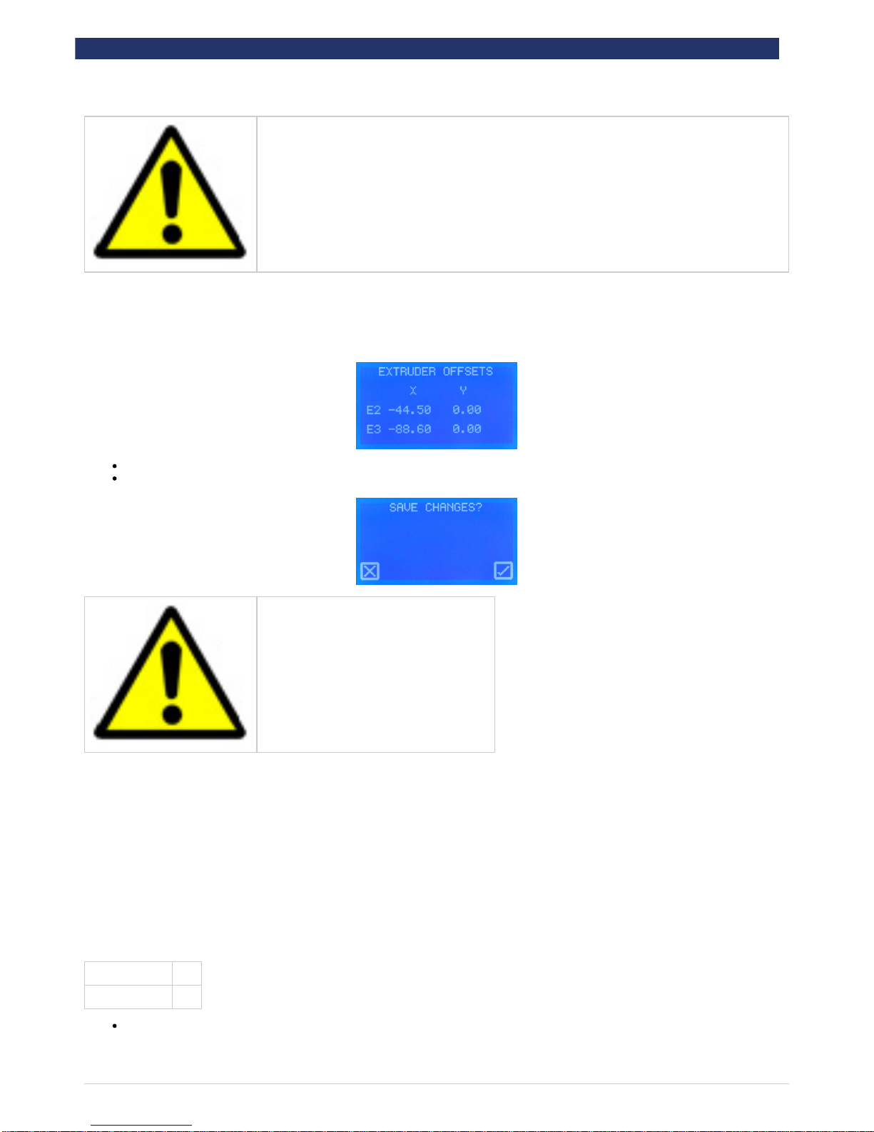
Extruder offsets defines the position of extruder 2 relative to extruder 1. Settings here should only be changed after performing a nozzle calibration
print. Visit our website to download the calibration procedure and determine the offsets values.
Touch the value to select the parameter. Use up and down arrows to alter the values.
Press the Function button to save the setting to the printer’s memory, which is retained when the power is turned off:
Incorrect values will severely affect print quality.
Level bed
See .Check the bed is level
Set Z height
See .Check the bed is referenced to the extruder nozzles
General settings
General settings are designed for advanced use. Defaults are shown below:
Ignore G92 Yes
Enable Hopping Yes
Touch the parameter to change its value
Page 40
Rapman 3.2 Operations Manual
Page 40
Incorrect general settings will severely affect the print quality. Do not change any general settings without fully
understanding each setting first.
The following two sections for explain the general settings:
Ignore G92
The "ignore G92" setting is required because of the previous method of managing extruder offsets which involves using the Gcode G92 command.
The user was required to determine the extruder 2 offset value through printing the calibration print. The calculated offset value was then entered
into Axon. During Gcode generation, Axon inserts a G92 offset command to offset the carriage by the user calculated offset amount.
Therefore all Axon generated Gcode files that utilise two extruders contain G92 commands to apply the extruder 2 offsets. A drawback of this
approach is that the Gcode file is printer dependent because the Gcode file contains the unique extruder offsets for the printer that was calibrated.
In order to make the Gcode files portable between printers, the extruder offsets are entered directly into the printer memory with firmware V4.1.0
onwards. This achieves moving the extruder offsets from the Gcode file and into the printer. When the printer utilises extruder 2, it reads the offsets
from memory.
When the extruder offsets are loaded from memory, the Axon generated G92 commands in the Gcode file must be ignored by the printer. Otherwise
the Axon generated G92 extruder offsets will be applied in addition to the printer memory extruder offsets, resulting in print failure.
Typically the desired functionality will be to ignore the Axon generated G92 offsets so the printer memory extruder offsets are applied solely.
However an advanced user may want to use G92 to produce an offset for a number of reasons, in which case the "ignore G92" option is provided.
Hopping
By default this setting is enabled on the 3D-Touch and disabled on the RapMan. The setting is accessed via Settings Menu -> General Settings.
Hop causes the bed to lower 1mm during a non-extruding move, and raise 1mm when the destination position has been reached. This reduces the
chance of the extruder hot end hitting part of the model and causing an XY shift. It also reduces the chance of the extruder hot end knocking over a
small delicate pillar shape for example.
Page 41

Rapman 3.2 Operations Manual
Page 41
e. Upgrading your printer firmware
Upgrading your printer firmware will improve the print and operational performance for your printer.
Click for free firmware upgrades. Alternatively please go to: www.bitsfrombytes.com > Support > Technical Resources > Downloads.here
For firmware release dates visit the software section at our forum: .http://www.bitsfrombytes.com/forum
Page 42
Rapman 3.2 Operations Manual
Page 42
f. Handling a ground-out filament
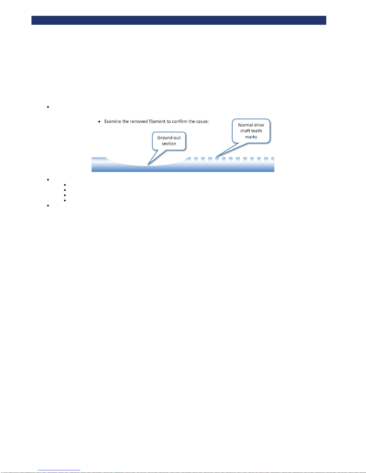
If a pressure bearing is poorly assembled, or the nozzle suffers from a blockage (e.g. printing too close to the bed), the back of the filament may be
ground out by the extruder drive shaft. The drive shaft will then be unable to push the filament down into the nozzle, preventing the extruder from
extruding. This is normally indicated by a fast build-up of plastic dust around the pressure bearing.
Heat extruder to melt plastic using "Extruder control".
Examine the removed filament to confirm the possible cause. Here are some suggestions:
Snagged filament reel preventing filament form entering the extruder
Under tightened pressure bearing
Blocked nozzle from poor filament tip preparation
Nozzle too close to bed during print
Reload the filament, as per "Load the extruders" taking care to prepare the tip of the filament as specified.
Page 43

Rapman 3.2 Operations Manual
Page 43
10. Print your own models
Now your printer is set up, you will need to return to our Technical Resources website by clicking the logo at the top of the screen (or visit
www.bitsfrombytes.com -> Support -> Technical Resources) to:
Download and install Axon software to process your own STL models ( ).click here
Pick up some printing tips from our or .online FAQ design for printing page
Page 44

Rapman 3.2 Operations Manual
Page 44
11. Troubleshooting
Please make sure that all steps in this manual have been followed, and the user is aware of all content in .Further operations
Click for troubleshooting guides. Alternatively please go to: www.bitsfrombytes.com > Support > Technical Resources > Troubleshoothere
a problem
Click to raise a support ticket. Alternatively please go to: www.bitsfrombytes.com > Support > Submit a tickethere
Page 45

Rapman 3.2 Operations Manual
Page 45
12. Specifications
Please visit our website at to view specification sheets on the RapMan.http://www.bitsfrombytes.com
Page 46

Rapman 3.2 Operations Manual
Page 46
13. Appendix
Manual version
Version Description Date
1.0.0 Original release 23/11/2011
Page 47

Rapman 3.2 Operations Manual
Page 47
Home
Error formatting macro: redirect: java.lang.NullPointerException
 Loading...