

Page 1

UNITE AP4
ACCESS POINT
INSTALLATION INSTRUCTIONS
MONTAGEANLEITUNG
Page 2

Page 3

Table of Contents
1. Safety inructions. . . . . . . . . . . . . . . . . . . . . . . . . . . . . . . . . . . . . . . . . . . . . . . . . . . . . . . . . . . . . . . . . . . . . 6
2. Supplied accessories . . . . . . . . . . . . . . . . . . . . . . . . . . . . . . . . . . . . . . . . . . . . . . . . . . . . . . . . . . . . . . . . . . 8
3. Application . . . . . . . . . . . . . . . . . . . . . . . . . . . . . . . . . . . . . . . . . . . . . . . . . . . . . . . . . . . . . . . . . . . . . . . . . . . . 8
4. Connections and elements . . . . . . . . . . . . . . . . . . . . . . . . . . . . . . . . . . . . . . . . . . . . . . . . . . . . . . . . . . . . 9
5. Use10
6. Inallation. . . . . . . . . . . . . . . . . . . . . . . . . . . . . . . . . . . . . . . . . . . . . . . . . . . . . . . . . . . . . . . . . . . . . . . . . . . . 10
6.1 Mounting to a wall/ceiling. . . . . . . . . . . . . . . . . . . . . . . . . . . . . . . . . . . . . . . . . . . . . . . . . . . . . . . . 11
6.2 Mounting on a and. . . . . . . . . . . . . . . . . . . . . . . . . . . . . . . . . . . . . . . . . . . . . . . . . . . . . . . . . . . . . 13
6.3 Mounting on a VESA adapter plate. . . . . . . . . . . . . . . . . . . . . . . . . . . . . . . . . . . . . . . . . . . . . . . 15
6.4 Use a secondary safety rope. . . . . . . . . . . . . . . . . . . . . . . . . . . . . . . . . . . . . . . . . . . . . . . . . . . . . 17
7. How to use several Unite AP . . . . . . . . . . . . . . . . . . . . . . . . . . . . . . . . . . . . . . . . . . . . . . . . . . . . . . . . . . . 17
8. Technical specifications . . . . . . . . . . . . . . . . . . . . . . . . . . . . . . . . . . . . . . . . . . . . . . . . . . . . . . . . . . . . . . 18
Pin assignment. . . . . . . . . . . . . . . . . . . . . . . . . . . . . . . . . . . . . . . . . . . . . . . . . . . . . . . . . . . . . . . . . . . . . . . . . . . 20
Pinout RJ45. . . . . . . . . . . . . . . . . . . . . . . . . . . . . . . . . . . . . . . . . . . . . . . . . . . . . . . . . . . . . . . . . . . . . . . . . . . . . . . 20
Network build-up . . . . . . . . . . . . . . . . . . . . . . . . . . . . . . . . . . . . . . . . . . . . . . . . . . . . . . . . . . . . . . . . . . . . . . . . . 21
Dimensions. . . . . . . . . . . . . . . . . . . . . . . . . . . . . . . . . . . . . . . . . . . . . . . . . . . . . . . . . . . . . . . . . . . . . . . . . . . . . . . 38
Polar Pattern Antennas. . . . . . . . . . . . . . . . . . . . . . . . . . . . . . . . . . . . . . . . . . . . . . . . . . . . . . . . . . . . . . . . . . . 43
Inhaltsverzeichnis
1. Sicherheitsinformationen . . . . . . . . . . . . . . . . . . . . . . . . . . . . . . . . . . . . . . . . . . . . . . . . . . . . . . . . . . . . . 22
2. Lieferumfang . . . . . . . . . . . . . . . . . . . . . . . . . . . . . . . . . . . . . . . . . . . . . . . . . . . . . . . . . . . . . . . . . . . . . . . . . 24
3. Verwendung . . . . . . . . . . . . . . . . . . . . . . . . . . . . . . . . . . . . . . . . . . . . . . . . . . . . . . . . . . . . . . . . . . . . . . . . . . 24
4. Anschlüsse und Elemente. . . . . . . . . . . . . . . . . . . . . . . . . . . . . . . . . . . . . . . . . . . . . . . . . . . . . . . . . . . . . 25
5. Inbetriebnahme . . . . . . . . . . . . . . . . . . . . . . . . . . . . . . . . . . . . . . . . . . . . . . . . . . . . . . . . . . . . . . . . . . . . . . 26
6. Montage . . . . . . . . . . . . . . . . . . . . . . . . . . . . . . . . . . . . . . . . . . . . . . . . . . . . . . . . . . . . . . . . . . . . . . . . . . . . . 26
6.1 Montage an Wand/Decke . . . . . . . . . . . . . . . . . . . . . . . . . . . . . . . . . . . . . . . . . . . . . . . . . . . . . . . 27
6.2 Montage auf einem Stativ . . . . . . . . . . . . . . . . . . . . . . . . . . . . . . . . . . . . . . . . . . . . . . . . . . . . . . . 29
6.3 Montage auf VESA-Adapterplatte . . . . . . . . . . . . . . . . . . . . . . . . . . . . . . . . . . . . . . . . . . . . . . . 31
6.4 Sekundärsicherung (Sicherungsleine) verwenden. . . . . . . . . . . . . . . . . . . . . . . . . . . . . . . . 33
7. Mehrere Unite AP4 einsetzen. . . . . . . . . . . . . . . . . . . . . . . . . . . . . . . . . . . . . . . . . . . . . . . . . . . . . . . . . . 33
8. Technische Daten . . . . . . . . . . . . . . . . . . . . . . . . . . . . . . . . . . . . . . . . . . . . . . . . . . . . . . . . . . . . . . . . . . . . 34
Anschlussbelegung . . . . . . . . . . . . . . . . . . . . . . . . . . . . . . . . . . . . . . . . . . . . . . . . . . . . . . . . . . . . . . . . . . . . . . 36
Anschlussbelegung RJ45 . . . . . . . . . . . . . . . . . . . . . . . . . . . . . . . . . . . . . . . . . . . . . . . . . . . . . . . . . . . . . . . . . 36
Netzwerkaufbau. . . . . . . . . . . . . . . . . . . . . . . . . . . . . . . . . . . . . . . . . . . . . . . . . . . . . . . . . . . . . . . . . . . . . . . . . . 37
Abmessungen. . . . . . . . . . . . . . . . . . . . . . . . . . . . . . . . . . . . . . . . . . . . . . . . . . . . . . . . . . . . . . . . . . . . . . . . . . . . 38
Richtcharakteriik Antennen. . . . . . . . . . . . . . . . . . . . . . . . . . . . . . . . . . . . . . . . . . . . . . . . . . . . . . . . . . . . . 43
Page 4

4
This device complies with Pa 15 of the FCC Rules and with Indury Canada licence-exempt RSS
andard(s). Operation is subject to the following two conditions: (1) this device may not cause harmful
inteerence, and (2) this device mu accept any inteerence received, including inteerence that
may cause undesired operation.
Le présent appareil e conforme aux CNR d’Indurie Canada applicables aux appareils radio
exempts de licence. L’exploitation e autorisée aux deux conditions suivantes: (1) l’appareil ne doit pas
produire de brouillage, et (2) l’utilisateur de l’appareil doit accepter tout brouillage radioélectrique subi,
même si le brouillage e susceptible d’en compromettre le fonctionnement.
This equipment has been teed and found to comply with the limits for a Class A digital device,
pursuant to Pa 15 of the FCC Rules. These limits are designed to provide reasonable protection
again harmful inteerence when the equipment is operated in a commercial environment. This
equipment generates, uses, and can radiate radio frequency energy and, if not inalled and used in
accordance with the inruction manual, may cause harmful inteerence to radio communications.
Operation of this equipment in a residential area is likely to cause harmful inteerence in which case
the user will be required to correct the inteerence at his own expense.
Changes or modifications made to this equipment not expressly approved by Beyerdynamic may void
the FCC authorization to operate this equipment.
Radiofrequency radiation exposure Information:
For body worn operation, this equipment has been teed and meets the FCC RF exposure guidelines
when used with the Beyerdynamic accessories supplied or designated for this product. Use of other
accessories may not ensure compliance with FCC RF exposure guidelines.
Ee produto eá homologado pela Anatel, de acordo com os procedimentos regulamentados pela
Resolução n°. 242/2000 e atende aos requisites técnicos aplicados, incluindo os limites de exposição
da Taxa de Absorção Específica referente a campos elétricos, magnéticos e eletromagnéticos de
radiofrequência de acordo com as Resoluções n°. 303/2002 e 533/2009.
Unite AP4 – Access Point
Japanese Radio Law and Japanese Telecommunications Business Law Compliance:
This device is granted pursuant to the Japanese Radio Law (電波法)
and the Japanese Telecommunications Business Law (電気通信事業法).
This device should not be modified (otherwise the granted designation number will become invalid).
Page 5
Unite AP4 – Access Point
Compliance Information
Country Approval
SA
U
CC ID: OSDUNITEAP4
F
5
english
anada
C
urope
E
Japan
C: 3628C-UNITEAP4
I
he devices conforms to the EU guidelines
T
(EMC) 2014/30/EU
(LVD) 2014/35/EU
(RED) 2014/53/EU
as atteed by the CE mark.
R 202-SMH013
T D 19-0007 202
Page 6

6
The Unite AP4 access point has been designed for the wireless Unite communication system from
beyerdynamic. For detailed descriptions of its use, please refer to the operating instructions for the
complete system, which can be downloaded from the internet at www.beyerdynamic.com/unite .
Unite AP4 – Access Point
1. Safety inructions
1. Read these inructions.
2. Keep these inructions.
3. Heed all warnings.
4. Follow all inructions.
5. Do not use this device near water.
6. Clean only with a dry cloth.
7. Do not inall near any heat sources such as radiators, heat regiers, oves, or other
apparatus (including amplifiers) that produce heat.
8. Do not modify the power plug of the supplied power cable.
9. Protect the power cable from being pinched or bent.
10. Only use accessories specified by the manufacturer.
11. Unplug this apparatus during lightning orms or when unused for long periods of
time.
12. Refer all servicing to qualified service personnel. Servicing is required when the
apparatus has been damaged in any way, such as power supply cord or plug is
damaged, liquid has been spilled or objects have fallen into the apparatus, the
apparatus has been exposed to rain or moiure, does not operate normally, or has
been dropped.
Disclaimer
• beyerdynamic GmbH & Co. KG will not be liable if any damage, injury or accident occurs
due to negligent, incorrect or inappropriate operation of the product.
Location
• If you transpo the equipment to another location take care to ensure that it is
adequately secured and can never be damaged by being dropped or by impacts on
the equipment.
Fire hazard
• Never place naked flames (e.g. candles) near the equipment.
Humidity / heat sources
• Never expose the equipment to rain or a high level of humidity. For this reason do not
inall it in the immediate vicinity of swimming pools, showers, damp basement rooms
or other areas with unusually high atmospheric humidity.
• Never place objects containing liquid (e.g. vases or drinking glasses) on the equipment.
Liquids in the equipment could cause a sho circuit.
• Do not inall near any heat sources such as radiators, heat regiers, oves or other
apparatus (including amplifiers) that produce heat.
Connection
• Protect all cables from being walked on or pinched.
• Lay all connection cables so that they do not present a trip hazard.
• Whenever working on the inputs and outputs of the equipment switch o power.
Page 7

Unite AP4 – Access Point
• Check whether the connection figures comply with the exiing mains supply. Serious
damage could occur due to connecting the syem to the wrong power supply. An
incorrect mains voltage could damage the equipment or cause an electric shock.
• Please note that dierent operating voltages require the use of dierent types of power
cable and plugs.
Please refer to the following table:
Voltage Power plug according to standard
110 to 125 V UL817 and CSA C 22.2 no 42.
220 to 230 V CEE 7 page VII, SR section 107-2-D1/IEC 83 page C4.
240 V BS 1363 (1984): “Specification for 13A fused plugs and switched and un-switched socket outlets.”
• If the equipment causes a blown fuse or a sho circuit, disconnect it from the mains
and have it checked and repaired.
• Do not hold the power supply with wet hands. There mu be no water or du on the
contact pins. In both cases you could receive an electric shock.
• The mains cable mu be firmly connected. If it is loose there is a fire hazard.
• Always pull out the power supply from the mains and/or from the equipment by the
plug – never by the cable. The cable could be damaged and cause an electric shock or
fire.
• Do not use the equipment if the power supply is damaged.
• If you connect defective or unsuitable accessories, the equipment could be damaged.
Only use connection cables available from or recommended by beyerdynamic. If you
use cables you have made up yourself, all claim to warranty is null and void.
• In order to switch o the device disconnect the power plug from the power socket.
7
english
Disconnect
• For pluggable equipment, the socket-outlet shall be near the equipment and shall be
easily accessible.
Wall/ceiling mounting
• Before mounting the Unite AP4 to the wall/ceiling, make sure that there are no electrical,
or gas lines or water pipes behind the planned drilling locations. If necessary, check this
with a line detector or ask an expe.
It is a significant hazard when electrical or gas lines or water pipes are damaged
during drilling.
Maintenance
• Only clean the device with a slightly damp or dry cloth. Never use solvents as these
damage the suace.
Trouble shooting / servicing
• Do not open the device without authorisation.
• Leave all service work to authorised expe personnel.
Switching o
• The device does not have a separate on-o switch. To turn power o, unplug the power
cable from the AC/DC outlet. Make sure that you do not pull on the cable, but on the
mains plug.
Page 8

8
Ventilation
• Do not inse objects into the ventilation and other openings. You could damage the
device and/or injure yourself.
Measures to prevent damage
• Do not disassemble or make any changes to the device.
• Do not transpo the device while it is mounted on a tripod as this may result in injury or
accidents. Make sure that the tripod is solid enough to hold the device.
• Do not drop the unit and do not expose it to rong physical ress such as shock or
vibration.
Unite AP4 – Access Point
Disposal
This symbol on the product, in the instructions or on the packaging means that
your electrical and electronic equipment should be disposed at the end of its
life separately from your household waste. There are separate collection
systems for recycling in the EU. For more information, please contact the local
authority or your retailer where you purchased the product.
Simplified EU declaration of conformity
beyerdynamic hereby declares that the wireless transmission device complies with the EU
Directive 2014/53/EU (RED). The complete text of the EU declaration of conformity is
available online at the following address: http://www.beyerdynamic.com/cod
Trademark
The Dante® word mark and logos are regiered trademarks of Audinate Pty. Ltd and all
use of these trademarks by beyerdynamic is licensed. Other trademarks and trade names
are the propey of the respective owners.
2. Supplied accessories
1 x Unite AP4
1 x Inallation inructions
1 x Power supply with power cable,
depending on the country variant
1 x Thread adapter 1/2" – 3/8"
2 x Phoenix® plug-in terminal block, 2-row,
6-pin, contact spacing 3.5 mm
4 x Cover plates for mounting panel
4 x M5x10 screws (for Vesa adapter plate)
4 x M5 nut (for Vesa adapter plate)
3. Application
The Unite AP4 access point is a multifunctional device with which you can implement
dierent applications. The device is integrated into an exiing network via an Ethernet
cable. Depending on the configuration via the separate Unite Manager Soware
(operating inructions at www.beyerdynamic.com), the device works as a transmitter,
receiver or transceiver.
For each device there are a maximum of 4 DECT channels available. As 8 Unite AP4
devices can be connected to each other, a maximum of 32 DECT-channels can be
implemented.
Page 9
Unite AP4 – Access Point
4. Connections and elements
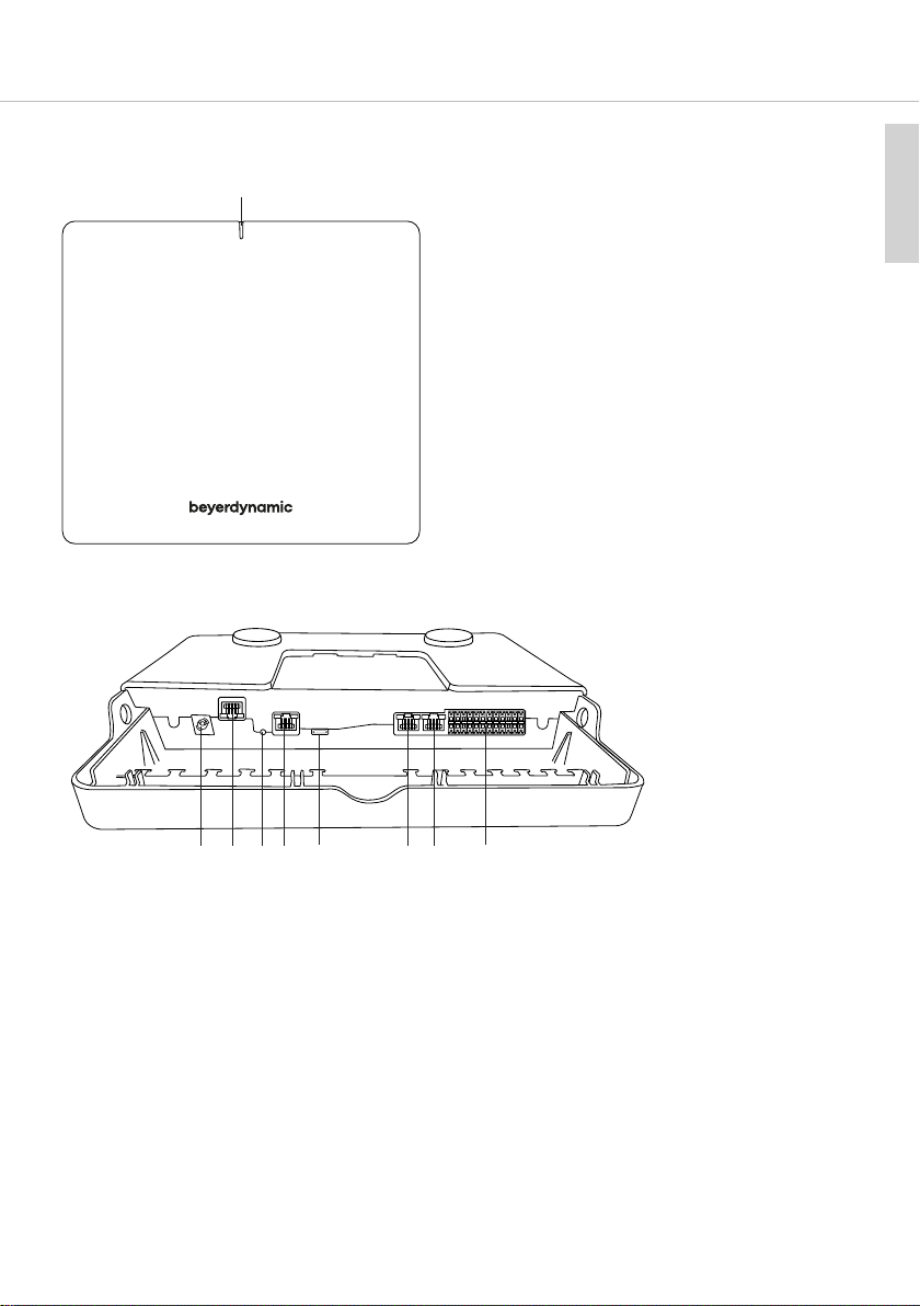
Front view
Rear view
9
english
Status LED
DC connection for the external, supplied power supply, 12 V DC / 3 A
Impoant: Use only the power supply supplied by beyerdynamic.
Dante® network connection with Power over Ethernet (PoE) function, RJ-45-socket
Reset button to reore the factory settings
LAN connection for configuration via the Unite Manager Soware, RJ-45-socket
USB connection
Sync signal input to cascade several Unite AP4, RJ-45-socket
Attention: No Ethernet connection!
Sync signal output to cascade several Unite AP4, RJ-45-socket
Attention: No Ethernet connection!
Audio inputs/outputs, channel 1 - 4, Phoenix®-terminal block socket for use with
supplied Phoenix terminal blocks, contact spacing 3.5 mm
Page 10
10
Unite AP4 – Access Point
5. Use
You will find a detailed description of the use/configuration of the Unite AP4 in the
separate manuals “Unite Syem Manual” and “Unite Manager Soware”.
6. Inallation
In order to ensure that the Unite receivers receive radio signals as good as possible, make
sure that the front of the Unite AP4 unit points to the area where the Unite receivers will be
operating. If reception problems occur, change the mounting position of the Unite AP4 in
the room. Make sure that there is a line of sight between the Unite AP4 and the receivers.
This can improve reception.
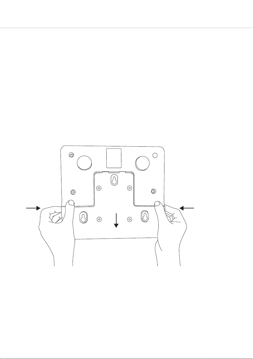
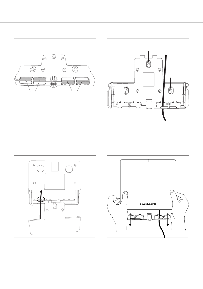
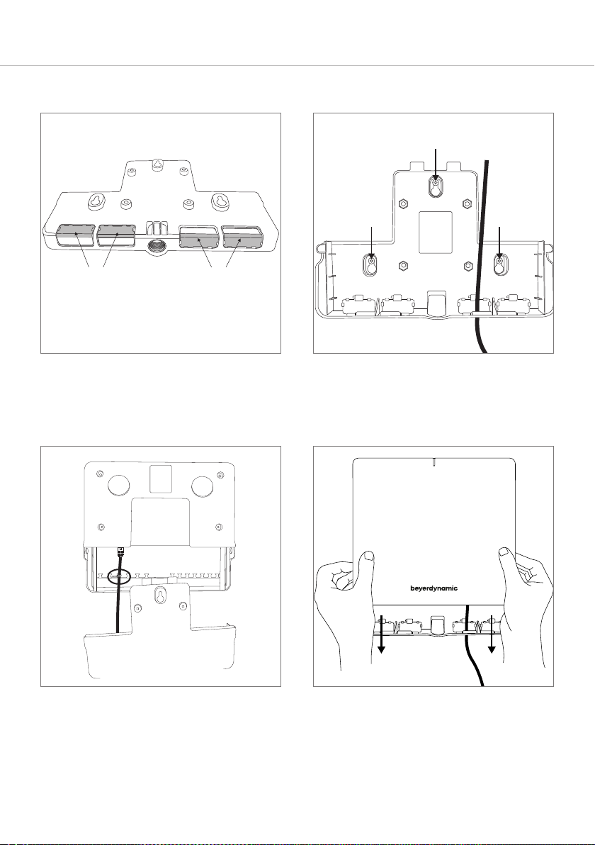
In order to inall the Unite AP4 and to connect the cable, you mu remove the mounting
plate from the housing fir. Please proceed as follows:
• Press the latches on the right and le hand side inwards.
• Remove the mounting panel downwards, refer also to the arrow in the drawing.
Page 11
Unite AP4 – Access Point
6.1 Mounting to a wall/ceiling
Caution:
• Before mounting the Unite AP4 to the wall/ceiling, make sure that there are no electrical,
or gas lines or water pipes behind the planned drilling locations. If necessary, check this
with a line detector or ask an expe.
• It is a significant hazard when electrical or gas lines or water pipes are damaged
during drilling.
Attention:
• For wall mounting, use appropriate wall plugs and screws.
Example: For a wooden wall use a universal screw, 4.5 x 30mm, pan head,
e.g. WIROX®-0201010450303
11
english
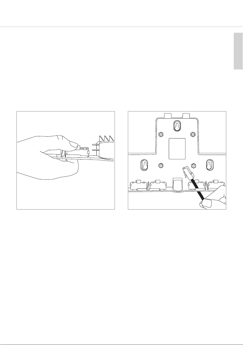
1. Remove the cover plates from the
mounting panel by pressing the large
latch.
2. Route all required connecting cables
through the openings of the mounting
panel.
Page 12
12
Unite AP4 – Access Point
able routing
C
ownwards
d
able routing
C
ackwards
b
3. Mount the cover plates to the
mounting panel according to the
cable routing.
4. Mount the mounting panel to the wall
or ceiling by using the three “keyhole
openings” with appropriate screws.
5. Connect the cables to the appropriate
connections.
Attach the cable with a cable tie to the
T-piece below the connection.
6. Put the device onto the mounting
panel until the latches on the right and
le hand side audibly click into place.
Refer also to the inallation
inructions on the mounting panel.
Attention: Please make sure that the
device is firmly mounted.
Page 13

Unite AP4 – Access Point
6.2 Mounting on a and
13
english
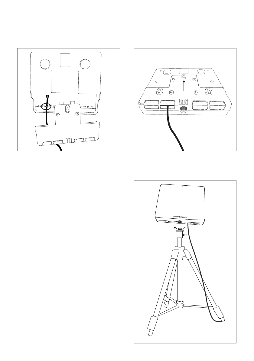
1. Press the cover plates on the large
latch from the mounting panel.
Cable routing
downwards
Cable routing
backwards
3. Attach the cover plates to the
mounting panel according to the
downward cable routing.
2. Route all required connecting cables
through the openings of the mounting
panel.
4. Connect the cables to the appropriate
connections.
Page 14
14
Unite AP4 – Access Point
5. Attach the cable with a cable tie to the
T-piece below the connection.
7. Mount the Unite AP4 on the thread of a
tripod with 5/8 thread.
For tripods with a 1/2" or 3/8 thread,
delivery includes an appropriate
adapter.
Upon reque, you can screw this
adapter into the 5/8 thread with a
flat-head screwdriver..
6. Replace the mounting panel until the
latches on the right and le hand side
audibly click into place.
Page 15
Unite AP4 – Access Point
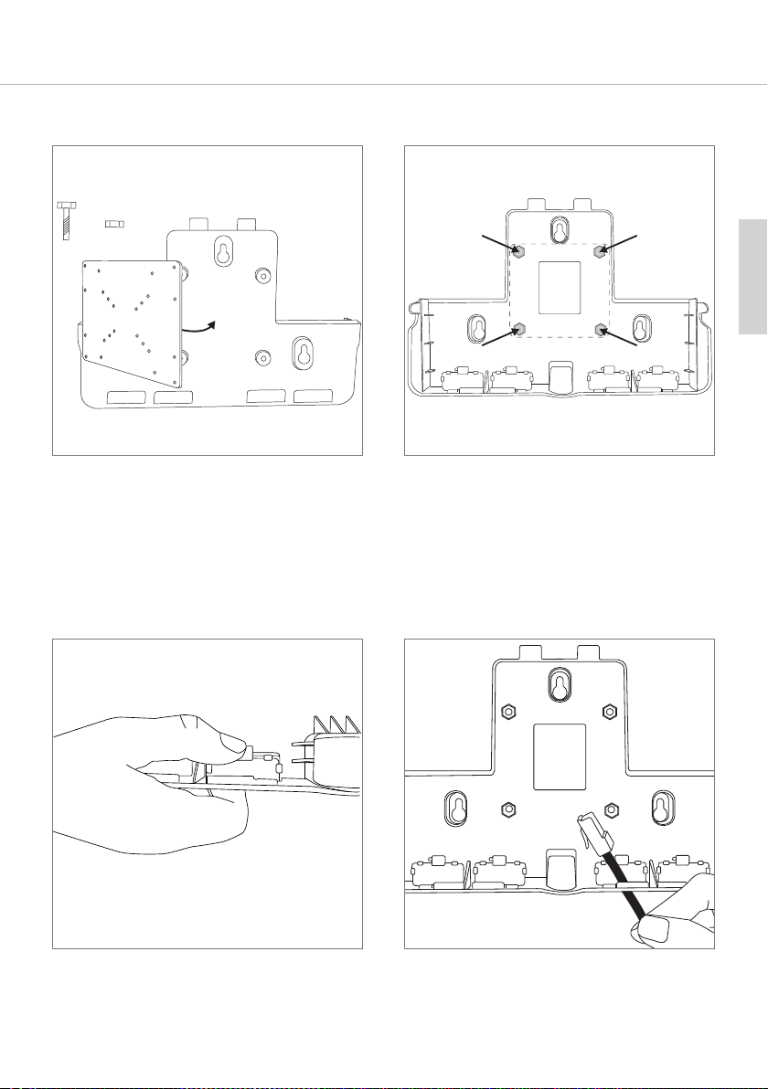
X4 X4
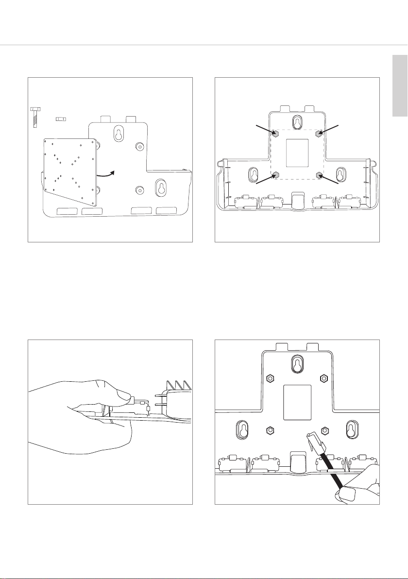
6.3 Mounting on a VESA adapter plate
15
english
1. Attach a VESA 75 x 75 plate with
4 screws (included in the delivery) via
the 4 holes to the mounting panel. The
diances between the 4 holes are
75 mm each.
Attention: When selecting the screws,
make sure that the screw is flush with
the nut and does not protrude into the
device.
3. Remove the cover plates from the
mounting panel by pressing the large
latch.
2. Faen the 4 screws on the inside of the
mounting panel with hex nuts.
Size of the nut: M5
4. Route all required connecting cables
through the openings of the mounting
panel.
Page 16
16
Unite AP4 – Access Point
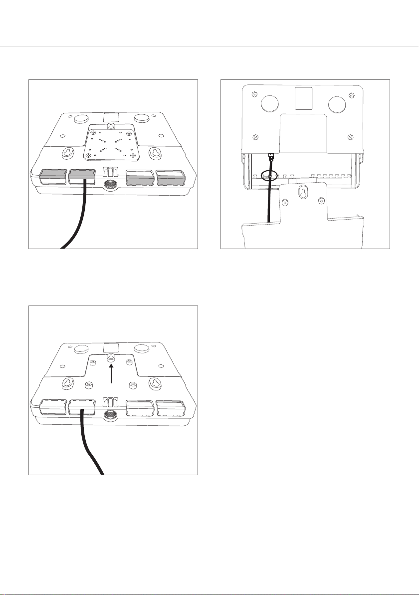
5. Mount the cover plates to the
mounting panel according to the
cable routing downwards.
7. Replace the mounting panel until the
latches on the right and le hand side
audibly click into place.
Attach the Unite AP4 to the desired
place via the VESA plate.
Attention: Make sure that the device is
firmly mounted.
6. Connect the cables to the appropriate
connections.
Attach the cable with a cable tie to the
T-piece below the connection.
Page 17

Unite AP4 – Access Point
...8
6.4 Use a secondary safety rope
The Unite AP4 has two openings through which you can route a secondary safety rope to
secure the Unite AP4 additionally again falling down.
In practice, it is the quality of the way in which the equipment is installed that influences
the safety of suspension systems for lighting, PAs, monitors, decorations and other objects
in the production and event business which are installed using fixing devices intended to
allow the equipment to be used in dierent places (e.g. spigots and sleeves or C hooks).
Such applications thus require a secondary safety component.
(Source: DGUV Safety for Events and Productions Version 3.2/2015-10)
For the preferred direction of threading, refer to the arrow in the drawing.
17
english
7. How to use several Unite AP
A maximum of 8 Unite AP4 can be connected with each other so that 32 channels can be
sent, received or sent and received – depending on the configuration.
• To synchronise the devices, connect the sync signal output of the fir Unite AP4 to the
sync signal input of the second Unite AP4.
The assignment mu be 1:1.
• Connect the Sync signal output of the second Unite AP4 to the Sync signal input of
the third Unite AP4 etc.
• The fir device acts as Sync Maer so that each subsequent device receives a clock
signal from the Sync Maer. In this way the individual DECT channels of the devices are
clocked. When using more than one Unite AP4 the synchronisation is absolutely
necessary to ensure the operation.
Sync Maer
1278
min. 2m
OUT
Synced Synced
IN
OUT
Use Cat 5e AWG 24/1 F/UTP cables or better.
Synced
min. 2m
IN
OUT
IN
Page 18

18
Attention:
• If several Unite AP4 are used in one room, a minimum diance of 2 m mu be
maintained between the individual units to avoid radio diurbances.
between two devices must not exceed 100 m. The total length of all Sync cables used to
connect the Unite AP4 devices to each other must not exceed 700 m.
Unite AP4 – Access Point
The cable length
8. Technical specifications
External power supply
Input voltage . . . . . . . . . . . . . . . . . . . . . . 100 – 240 V AC, 47-63 Hz
Input current . . . . . . . . . . . . . . . . . . . . . . max. 0,8 A
Output voltage . . . . . . . . . . . . . . . . . . . . 12 V DC
Output current. . . . . . . . . . . . . . . . . . . . . 3 A
Power cable . . . . . . . . . . . . . . . . . . . . . . . included, depending on the region
Cable length . . . . . . . . . . . . . . . . . . . . . . 2 m [2.19 yds.]
Unite AP4
DECT RF frequency range . . . . . . . . . . . . . 1880 - 1930 MHz, depending on the country
DECT transmission power . . . . . . . . . . . . . . up to 250 mW (peak), depending on the country
DECT operating range . . . . . . . . . . . . . . . . . up to 300 m outside (line of sight);
the actual operating range depends upon the
RF output settings, the surroundings, the signal
absorption, signal reflection and signal interference
RF coverage . . . . . . . . . . . . . . . . . . . . . . . . . . . up to 10,000 m2; the actual coverage depends upon the
RF output settings, the surroundings, the signal absorption,
signal reflection and signal interference
Audio bandwidth
High quality (HD) . . . . . . . . . . . . . . . . . . . . . 50 Hz - 14 kHz (-3 dB)
Operating mode. . . . . . . . . . . . . . . . . . . . . . . Broadcast (4 channels)
Encryption . . . . . . . . . . . . . . . . . . . . . . . . . . . . . AES-256 bit encryption
Antenna . . . . . . . . . . . . . . . . . . . . . . . . . . . . . . . Diversity, internal
Polar pattern of antennas . . . . . . . . . . . . . two omnidirectional antennas with front-facing main lobe
Minimum distance between
several Unite AP4 devices . . . . . . . . 2 m [2.19 yds.]
Connections. . . . . . . . . . . . . . . . . . . . . . . • Ethernet (RJ 45)
• USB-C (currently not implemented)
• DC input, DC 12 V, power consumption max. 12 W
• Sync input (RJ 45)
• Sync output (RJ 45)
• Digital: Dante® (RJ 45; PoE: 12 W IEEE 802.3af-2003,
36 V - 57 V, only 48 kHz sample rate supported)
• Analogue: Phoenix® socket, balanced,
contact spacing 3.5 mm [0.14"], two-rowed, 6-pin,
balanced and shielded connecting cables required
Input level (4-channel In): max. +7 dBu
Input level for 0 dBFS @ 0 dB Gain: +5 dBu
Page 19

Unite AP4 – Access Point
Required cable features for RJ 45 Ethernet, Dante® and Sync connectors
Cable type. . . . . . . . . . . . . . . . . . . . . . . Cat 5e AWG 24/1 F/UTP, shielded, assignment 1:1
Cable length for Ethernet,
Dante® and Sync. . . . . . . . . . . . . . . . . 100 m [109 yds.]
Total length of all Sync cables . . . max. 700 m [766 yds.]
Reset button. . . . . . . . . . . . . . . . . . . . . . . to restore the factory settings (network, audio, DECT)
Network default . . . . . . . . . . . . . . . . . . . DHCP (IP)
Indicator . . . . . . . . . . . . . . . . . . . . . . . . . . Status LED
Mounting for Vesa mount. . . . . . . . . . 75 x 75 mm [2.95" x 2.95"]
Mounting holes for
secondary safety rope. . . . . . . . . . . available (safety rope not included in the delivery)
Temperature range
Operation. . . . . . . . . . . . . . . . . . . . . . . . . . . . 0 to +40 °C [32 to 104 °F]
Storage . . . . . . . . . . . . . . . . . . . . . . . . . . . . . . -20 to +50 °C [-4 to 122 °F]
Relative humidity . . . . . . . . . . . . . . . . . . . . . . 0 to 90%
Dimensions (L x W x H). . . . . . . . . . . . . . 260 x 252 x 48 mm [10.2" x 9.92" x 1.89"]
Weight. . . . . . . . . . . . . . . . . . . . . . . . . . . . . 860 g [30.34 oz.]
19
english
Page 20

20
ControlReset
Green = Activity
Y
ellow = Link
Green = Activity
Y
ellow = Link
/ PoE
USB
DC In
12 V 3 A
Sync In Sync Out
Not for Ethernet!
Analog Out + 4 dBu
Analog In + 6 dBu
12 34
1
2
3
4
+-+
-
+-+
-
+-+
-
+-+
-
Pin assignment
Pinout RJ45
T-568A
1 2 3 4 5 6 7 8
Unite AP4 – Access Point
1 2 3 4 5 6 7 8
T-568B
shielded connector
housing
1 white/green 5 white/blue
2 green 6 orange
3 white/orange 7 white/brown
4 blue 8 brown
Important:
Please use shielded connector housings. Twist the shield of the cable and fold it backwards so that a connection between the shield of the cable and the connector housing is
1 white/orange 5 white/blue
2 orange 6 green
3 white/green 7 white/brown
4 blue 8 brown
shielded connector
housing
created when crimping the strain relief of the cable.
Use either the T-568A or T-568B pin assignment for both cable ends. Do not use both pin
assignments for one cable.
SF/UTPSF/UTP
Page 21

Unite AP4 – Access Point
Sync
Master
Network
Sync
Remote co ntrol
Dante (P oE)
Full-Dup lex
Broadcas t
or
RB(SLENNAHC*32
TNIU
or
D-LLUFROTSACDAO
TNEET
or
AROTENDA-)XELPDU
WOT
or
M-TOU/NI2 3GOLANA
KR
or
NTMAI&NGIROTNIMO
or
CETOMRE-ENANCET
or
NIOTRAUIGFNOC
or
A
AP
4PAotw
neewtbe
m2. nmi
AP
AP
snoictennoC
MetUni
naentniMa
tarugifnCo
gniortiMon
krowteNEoP
regana
cen
noit
t
chtiws
rvereS
PC
regraCh
ckaRtipckoC
re
DH
TCED
tmennorivendnanoiegrTCDE
n ongindepedslnnehac23otp*u
m007:htgnle-cnySlaTot!
00m1:4PAo wteenwetbhtgenle lbcam muixMa!
PT/UF/142GWAe5TCA!
eniLc nySnos liateD
egraCh
tipckoC
t
oitareop
daorBto
4P AhcEa
n
xelpDu-lluFrot sac
derugifno ce bna c4
Network build-up
The configuration of one or more Unite AP4 is performed via the free Unite Manager
Software: https://global.beyerdynamic.com/unite-manager.html
21
english
Page 22

22
Der Access Point Unite AP4 ist für das Drahtlos-System Unite von beyerdynamic vorgesehen. Detaillierte Beschreibungen zum Gebrauch entnehmen Sie bitte der Bedienungsanleitung des Gesamtsystems, welche Sie im Internet unter www.beyerdynamic.com/unite herunterladen können.
Unite AP4 – Access Point
1. Sicherheitsinformationen
1. Bitte lesen Sie diese Anweisungen.
2. Bitte bewahren Sie diese Anweisungen auf.
3. Bitte beachten Sie alle Warnhinweise.
4. Folgen Sie allen Anweisungen.
5. Verwenden Sie dieses Gerät nicht in der Nähe von Wasser.
6. Reinigen Sie das Gerät nur mit einem trockenen Tuch.
7. Montieren Sie das Gerät nicht neben Hitzequellen wie Heizkörpern, Wärmespeichern,
Öfen oder anderen Geräten (auch Leiungsverärkern), die Hitze abrahlen.
8. Nehmen Sie keine Veränderungen am Netzecker des beigelegten Netzkabels vor.
9. Sichern Sie das Netzkabel gegen Einquetschen oder Abknicken.
10. Verwenden Sie nur das vom Hereller benannte Zubehör für dieses Gerät.
11. Trennen Sie das Gerät vom Stromnetz, wenn ein Gewitter aufkommt oder wenn Sie es
voraussichtlich für längere Zeit nicht verwenden werden.
12. Alle Waungsarbeiten müssen von hieür qualifizieen Servicemitarbeitern durchge-
füh werden. Eine Waung i eorderlich, wenn das Gerät selb oder dessen Netzkabel beschädigt wurde, Flüssigkeiten oder Gegenände in das Gerät gelangt sind, das
Gerät Regen oder arker Feuchtigkeit ausgesetzt wurde, das Gerät nicht ordnungsgemä arbeitet oder es heruntergefallen i.
Haungsausschluss
• Die Firma beyerdynamic GmbH & Co. KG übernimmt keine Haung für Schäden am Pro-
dukt oder Verletzungen von Personen aufgrund unachtsamer, unsachgemäer, falscher
oder nicht dem vom Hereller angegebenen Zweck entsprechender Verwendung des
Produkts.
Stando
• Wenn Sie das Gerät an einen anderen O transpoieren, achten Sie darauf, dass es aus-
reichend gesiche i und niemand durch ein eventuelles Herunteallen oder Stoen am
Gerät verletzt werden kann.
Brandschutz
• Stellen Sie niemals oene Brandquellen (z.B. Kerzen) auf das Gerät.
Feuchtigkeit / Wärmequellen
• Setzen Sie das Gerät niemals Regen oder hoher Feuchtigkeit aus. Inallieren Sie es daher
nicht in unmittelbarer Nähe von Swimming Pools, Duschanlagen, feuchten Kellerräumen
oder sonigen Bereichen mit auergewöhnlich hoher Lufeuchtigkeit.
• Stellen Sie niemals mit Flüssigkeiten gefüllte Gegenände (z.B. Vasen oder Trinkgläser) auf
das Gerät. Flüssigkeiten in den Geräten können einen Kurzschluss verursachen.
• Inallieren und betreiben Sie das Gerät auch niemals in unmittelbarer Nähe von Heizkör-
pern, Beleuchtungsanlagen oder anderen wärmeerzeugenden Geräten.
Anschluss
• Verlegen Sie alle Kabel ets so, dass sie nicht durch schae Gegenände geknickt oder
gar durchgetrennt werden können.
Page 23

Unite AP4 – Access Point
23
• Verlegen Sie alle Anschlusskabel so, dass niemand darüber olpern und sich verletzen
kann.
• Schalten Sie bei allen Arbeiten an den Ein- und Ausgängen die Stromzufuhr aus.
• Überprüfen Sie, ob die Anschlusswee mit der vorhandenen Netzromversorgung über -
einimmen. Bei Anschluss des Syems an die falsche Stromversorgung können ernhae Schäden entehen. Eine falsche Netzspannung kann das Gerät und Netzteil
beschädigen oder einen elektrischen Schlag verursachen.
• Beachten Sie, dass für verschiedene Netzspannungen entsprechende Anschlusskabel er-
forderlich sind.
Siehe hierzu folgende Tabelle:
pannung
S
110 bis 125 V UL817 und CSA C 22.2 Nr. 42.
220 bis 230 V CEE 7 Seite VII, SR Abschnitt 107-2-D1/IEC 83 Seite C4.
240 V BS 1363 (1984): “Specification for 13A fused plugs and switched and un-switched socket outlets.”
etzecker nach Standard
N
• Wenn durch das Gerät eine Sicherung defekt oder ein Kurzschluss verursacht wurde, neh-
men Sie es vom Netz und lassen Sie es überprüfen und reparieren.
• Fassen Sie das Netzteil nicht mit nassen Händen an. An den Kontaktien da sich kein
Wasser oder Staub befinden. In beiden Fällen könnten Sie einen elektrischen Schlag erleiden.
• Das Netzkabel muss fe angeschlossen sein. I es lose, beeht Brandgefahr.
• Ziehen Sie das Netzteil immer am Stecker vom Netz und/oder vom Gerät - niemals am
Kabel. Das Kabel könnte beschädigt werden und einen elektrischen Schlag oder Brand
verursachen.
• Setzen Sie das Gerät nicht ein, wenn das Netzteil beschädigt i.
• Wenn Sie defektes oder ungeeignetes Zubehör anschlieen, kann das Gerät beschädigt
werden. Verwenden Sie daher nur die von beyerdynamic lieferbaren oder empfohlenen
Netzteile.
• Zum Trennen des Gerätes vom Netz ziehen Sie den Netzecker aus der Netzeckdose.
deutsch
Vom Netz trennen
• Achten Sie darauf, dass die Netzeckdose sich in der Nähe des Gerätes befindet und
leicht zugänglich i.
Wand-/Deckenmontage
• Bevor Sie den Unite AP4 an einer Wand/Decke befeigen, achten Sie darauf, dass sich
hinter den geplanten Bohrellen keine Elektro-, Gas- oder Wasserleitungen befinden.
Prüfen Sie dies ggf. mit einem Leitungsdetektor oder fragen Sie einen Fachmann.
Beim Bohren beschädigte Elektro-, Gas- oder Wasserleitungen ellen eine erhebliche
Gefahr dar.
Reinigung
• Reinigen Sie das Gerät nur mit einem leicht feuchtem oder trockenem Tuch. Verwenden
Sie niemals Lösungsmittel, da diese die Obeläche beschädigen.
Fehlerbeseitigung / Reparatur
• Önen Sie nicht eigenmächtig das Gerät.
• Überlassen Sie alle Servicearbeiten nur autorisieem Fachpersonal.
Page 24

24
Ausschalten
• Das Gerät hat keinen separaten Ein-/Ausschalter. Wenn Sie das Gerät ausschalten
möchten, ziehen Sie den Netzecker aus der Netzeckdose. Achten Sie darauf, dass Sie
nicht am Kabel ziehen, sondern am Netzecker.
Ventilation
• Stecken Sie keine Gegenände in die Lüungs- und andere Önungen. Sie könnten das
Gerät beschädigen und/oder sich verletzen.
Maßnahmen zur Vermeidung von Schäden
• Nehmen Sie das Gerät nicht auseinander und nehmen Sie keine Änderungen daran vor.
• Transpoieren Sie das Gerät nicht, während es auf einem Stativ montie i, da dies zu
Verletzungen und Unfällen führen kann. Achten Sie darauf, dass das Stativ abil genug i,
um das Gerät zu tragen.
• Lassen Sie das Gerät nicht fallen und setzen Sie es keinen arken physischen Belaungen
wie Stöen oder Vibrationen aus.
Unite AP4 – Access Point
Entsorgung
Dieses Symbol auf dem Produkt, in der Bedienungsanleitung oder auf der
Verpackung bedeutet, dass Ihre elektrischen und elektronischen Geräte am
Ende ihrer Lebensdauer gesondert vom Hausmüll entsorgt werden sollten. Es
gibt getrennte Sammelsysteme für das Recycling in der EU. Für weitere
Informationen wenden Sie sich bitte an die örtlichen Behörden oder an den
Händler, bei dem Sie das Produkt erworben haben.
Vereinfachte EU-Konformitätserklärung
Hiermit erklärt beyerdynamic, dass das Funkübertragungsgerät die EU-Richtlinie
2014/53/EU (RED) erfüllt. Der vollständige Text der EU-Konformitätserklärung ist im Internet
unter folgender Adresse zu finden: http://www.beyerdynamic.com/cod
Warenzeichen
Die Dante® Womarke und Logos sind eingetragene Marken der Firma Audinate Pty. Ltd und
jegliche Verwendung dieser Marken durch beyerdynamic i lizenzie. Andere Marken und
Handelsnamen gehören den jeweiligen Inhabern.
2. Lieferumfang
1 x Unite AP4
1 x Montageanleitung
1 x Netzteil mit Netzkabel, je nach
Ländervariante
1 x Gewindeadapter 1/2" – 3/8"
2 x Phoenix® eckbare Reihenklemme,
2-reihig, 6-polig, Raerma 3,5 mm
4 x Abdeckplättchen für Montageplatte
4 x M5x10 Schraube (für Vesa-Adapterplatte)
4 x M5 Mutter (für Vesa-Adapterplatte)
3. Verwendung
Der Access Point Unite AP4 i ein Multifunktionsgerät mit dem verschiedene Anwendungen realisie werden können. Das Gerät wird über ein Ethernetkabel in ein beehendes
Netzwerk eingebunden. Je nach Konfiguration über eine separate Soware (Bedienungsanleitung unter www.beyerdynamic.com) arbeitet das Gerät als Sender, Empfänger oder
als Sender/Empfänger (Transceiver).
Pro Gerät ehen max. 4 DECT-Kanäle zur Veügung. Da 8 Unite AP4 Geräte miteinander
verbunden werden können, werden bis zu 32 DECT-Kanäle realisie.
Page 25

Unite AP4 – Access Point
4. Anschlüsse und Elemente
Vorderansicht
Rückansicht
25
deutsch
Status-LED
DC-Anschluss für externes, beigelegtes Netzteil, 12 V DC / 3 A
Wichtig: Verwenden Sie nur das von beyerdynamic beigelegte Netzteil.
Dante®-Netzwerkanschluss mit Power over Ethernet (PoE) Funktion, RJ-45-Buchse
Reset-Tae zum Wiederherellen der Werkseinellungen
LAN-Anschluss zur Konfiguration über die Unite Manager Soware, RJ-45-Buchse
USB-Anschluss
Sync-Signaleingang zur Kaskadierung mehrerer Unite AP4, RJ-45-Buchse
Achtung: Kein Ethernet-Anschluss!
Sync-Signalausgang zur Kaskadierung mehrerer Unite AP4, RJ-45-Buchse
Achtung: Kein Ethernet-Anschluss!
Audio Ein-/Ausgänge, Kanäle 1 - 4, Phoenix®-Reihenklemmenbuchse zur Verwendung
mit beigelegten Phoenix-Reihenklemmen, Raerma 3,5 mm
Page 26

26
Unite AP4 – Access Point
5. Inbetriebnahme
Eine detailliee Beschreibung der Inbetriebnahme/Konfiguration des Unite AP4 finden Sie
in den separaten Anleitungen „Unite Syemanleitung“ und „Unite Manager Soware“.
6. Montage
Für einen möglich guten Funkempfang der Unite Empfänger sollten Sie darauf achten,
dass die Vorderseite des Unite AP4 Gerätes in den Bereich zeigt, in welchem sich die Unite
Empfänger in Betrieb befinden werden. Sollten Sie Empfangsprobleme feellen, verändern Sie die Montageposition des Unite AP4 im Raum. Achten Sie darauf, dass zwischen
Unite AP4 und Empfängern möglich eine Sichtverbindung beehen kann. Auf diese
Weise kann sich der Empfang verbessern.
Für die Montage des Unite AP4 und zum Anschluss der Kabel müssen Sie zunäch die
Montageplatte vom Gehäuse abnehmen. Gehen Sie dabei wie folgt vor:
• Rechts und links die seitlichen Riegel nach innen drücken
• Montageplatte nach unten entnehmen, siehe Pfeilrichtung in Abbildung.
Page 27

Unite AP4 – Access Point
6.1 Montage an Wand/Decke
Vorsicht:
• Bevor Sie den Unite AP4 an einer Wand/Decke befeigen, achten Sie darauf, dass sich
hinter den geplanten Bohrellen keine Elektro-, Gas- oder Wasserleitungen befinden.
Prüfen Sie dies ggf. mit einem Leitungsdetektor oder fragen Sie einen Fachmann.
Beim Bohren beschädigte Elektro-, Gas- oder Wasserleitungen ellen eine erhebliche
Gefahr dar.
Achtung:
• Benutzen Sie für die Wandmontage die für die Wandbeschaenheit entsprechenden
Dübel und Schrauben.
Beispiel: Für eine Holzwand verwenden Sie Universalschrauben, 4,5 x 30 mm, Halbrundkopf, z.B. WIROX®-0201010450303
27
deutsch
1. Drücken Sie Abdeckplättchen an der
groen Ranase von der Montageplatte heraus.
2. Führen Sie alle benötigten Anschlusskabel durch die Önungen der
Montageplatte.
Page 28
28
Unite AP4 – Access Point
abelführung
K
ach unten
n
abelführung
K
ach hinten
n
3. Befeigen Sie die Abdeckplättchen
entsprechend der Kabelführung nach
unten wieder an der Montageplatte.
4. Montageplatte über die drei „Schlüsselloch-Önungen“ an Wand oder
Decke mit entsprechenden Schrauben
befeigen.
5. Schlieen Sie die Kabel an den
entsprechenden Anschlüssen an.
Fixieren Sie das Kabel mit einem Kabelbinder am T-Stück unterhalb des Anschlusses.
6. Setzen Sie die Montageplatte wieder
ein bis die seitlichen Riegel hörbar einraen. Siehe auch den Montagehinweis auf der Montageplatte.
Achtung: Bitte kontrollieren Sie, ob das
Gerät fe montie i.
Page 29

Unite AP4 – Access Point
6.2 Montage auf einem Stativ
29
deutsch
1. Drücken Sie Abdeckplättchen an der
groen Ranase von der Montageplatte heraus.
Kabelführung
nach unten
Kabelführung
nach hinten
3. Befeigen Sie die Abdeckplättchen
entsprechend der Kabelführung nach
unten wieder an der Montageplatte.
2. Führen Sie alle benötigten Anschlusskabel durch die Önungen der
Montageplatte.
4. Schlieen Sie die Kabel an den
entsprechenden Anschlüssen an.
Page 30

30
Unite AP4 – Access Point
5. Fixieren Sie das Kabel mit einem Kabelbinder am T-Stück unterhalb des Anschlusses.
7. Befeigen Sie den Unite AP4 über das
Gewinde auf einem Stativ mit 5/8"-Gewinde.
Für Stative mit einem 1/2"- oder
3/8"-Gewinde i im Lieferumfang ein
entsprechendes Reduzierück enthalten.
Bei Beda können Sie dieses Reduzierück mit einem Schlitzschraubendreher in das 5/8"-Gewinde einschrauben.
6. Setzen Sie die Montageplatte wieder
ein bis die seitlichen Riegel hörbar einraen.
Page 31
Unite AP4 – Access Point
X4 X4
6.3 Montage auf VESA-Adapterplatte
31
deutsch
1. Befeigen Sie eine VESA 75x75 Platte
mit den 4 beigelegten Schrauben über
die 4 Löcher auf der Montageplatte.
Die Abände zwischen den 4 Löchern
betragen jeweils 75 mm.
Achtung: Bei der Auswahl der Schrauben achten Sie bitte darauf, dass die
Schraube mit der Mutter bündig abschliet und nicht ins Gerät hineinragt.
3. Drücken Sie Abdeckplättchen an der
groen Ranase von der Montageplatte heraus.
2. Auf der Innenseite der Montageplatte
befeigen Sie die 4 Schrauben mit
Sechskantmuttern befeigen.
Gröe der Mutter: M5
4. Führen Sie alle benötigten Anschlusskabel durch die Önungen der
Montageplatte.
Page 32

32
Unite AP4 – Access Point
5. Befeigen Sie die Abdeckplättchen
entsprechend der Kabelführung nach
unten wieder an der Montageplatte.
7. Setzen Sie die Montageplatte wieder
ein bis die seitlichen Riegel hörbar einraen.
Befeigen Sie den Unite AP4 über die
Vesa-Platte am gewünschten
Montageplatz.
Achtung: Bitte kontrollieren Sie, ob das
Gerät fe montie i.
6. Schlieen Sie die Kabel an den
entsprechenden Anschlüssen an.
Fixieren Sie das Kabel mit einem Kabelbinder am T-Stück unterhalb des Anschlusses.
Page 33

Unite AP4 – Access Point
...8
6.4 Sekundärsicherung (Sicherungsleine) verwenden
Der Unite AP4 veügt über zwei Önungen durch die Sie eine Sekundärsicherung
(Sicherungsleine) führen und den Unite AP4 zusätzlich gegen Herunteallen sichern
können.
In der Praxis wird bei Leuchten, Lautsprechern, Monitoren, Dekorationen und anderen
Gegenständen im Produktions- und Veranstaltungsbetrieb, die mit Befestigungseinrichtungen für osveränderliche Verwendung (z. B. Zapfen und Hülse, C-Haken) montie
werden, die Sicherheit der Aufhängung durch die Qualität der Montage am Einsatzo beeinflusst. Deshalb ist für diese Anwendungen eine Sekundärsicherung erforderlich.
(Quelle: DGUV_Information_215_313.pdf, März 2017)
Für die Vorzugsrichtung zum Einfädeln siehe die Pfeilrichtung in der Abbildung.
33
deutsch
7. Mehrere Unite AP4 einsetzen
Maximal können 8 Unite AP4 miteinander verbunden werden, so dass auf 32 Kanälen gesendet, empfangen oder gesendet und empfangen werden kann – je nach Konfiguration.
• Um die Geräte miteinander zu synchronisieren, verbinden Sie den Sync Signalausgang
des eren Unite AP4 mit dem Sync Signaleingang des zweiten Unite AP4. Verwenden Sie
hieür Cat 5e AWG 24/1 F/UTP Kabel oder besser. Die Belegung muss 1:1 sein.
• Verbinden Sie den Sync Signalausgang des zweiten Unite AP4 mit dem Sync Signaleingang des dritten Unite AP4 usw.
• Das ere Gerät fungie als Sync Maer. Jedes nachfolgende Gerät erhält dadurch ein
Taktsignal vom Sync Maer. Dadurch werden die einzelnen DECT-Kanäle der Geräte getaktet. Die Synchronisation bei Verwendung von mehr als einem Unite AP4 i zwingend
eorderlich, um den Betrieb zu gewährleien.
Sync Maer
1278
min. 2m
OUT
Synced Synced
IN
OUT
IN
min. 2m
OUT
Synced
IN
Page 34

34
Achtung:
• Werden mehrere Unite AP4 in einem Raum eingesetzt, muss zwischen den einzelnen Geräten jeweils ein Mindeaband von 2 m eingehalten werden, um Funkörungen zu vermeiden. Die Kabellänge zwischen zwei Geräten darf nicht mehr als 100 m betragen. Die
Gesamtlänge aller Sync-Kabel zur Verbindung der Unite AP4 Geräte untereinander darf nicht
mehr als 700 m betragen.
Unite AP4 – Access Point
8. Technische Daten
Externes Netzteil
Eingangsspannung . . . . . . . . . . . . . . . . 100 – 240 V AC, 47-63 Hz
Eingangsstrom. . . . . . . . . . . . . . . . . . . . . max. 0,8 A
Ausgangsspannung . . . . . . . . . . . . . . . 12 V DC
Ausgangsstrom. . . . . . . . . . . . . . . . . . . . 3 A
Netzkabel. . . . . . . . . . . . . . . . . . . . . . . . . . je nach Region beigelegt
Kabellänge . . . . . . . . . . . . . . . . . . . . . . . . 2 m
Unite AP4
HF-Frequenzbereich DECT . . . . . . . . . . . . . 1880 - 1930 MHz, länderabhängig
Sendeleistung DECT . . . . . . . . . . . . . . . . . . . bis zu 250 mW (Spitze), länderabhängig
Reichweite DECT. . . . . . . . . . . . . . . . . . . . . . . bis zu 300 m bei Sichtverbindung im Freien;
die tatsächliche Reichweite hängt von der
HF-Leistungseinstellung, der Umgebung, der
Signalabsorption, -reflexion und -interferenz ab
HF-Abdeckung. . . . . . . . . . . . . . . . . . . . . . . . . bis zu 10.000 m2; die tatsächliche Reichweite hängt von der
HF-Leistungseinstellung, der Umgebung, der
Signalabsorption, -reflexion und -interferenz ab
Audiobandbreite
Hohe Qualität (HD) . . . . . . . . . . . . . . . . . . . 50 Hz - 14 kHz (-3 dB)
Betriebsart . . . . . . . . . . . . . . . . . . . . . . . . . . . . Broadcast (4 Kanäle)
Verschlüsselung . . . . . . . . . . . . . . . . . . . . . . . AES-256-Verschlüsselung
Antennen . . . . . . . . . . . . . . . . . . . . . . . . . . . . . . Diversity, integriert
Richtcharakteristik Antennen . . . . . . . . . . zwei Rundstrahlantennen mit frontseitiger Hauptkeule
Mindestabstand zwischen
mehreren Unite AP4 Geräten . . . . . 2 m
Anschlüsse . . . . . . . . . . . . . . . . . . . . . . . . • Ethernet (RJ 45)
• USB-C (derzeit nicht implementiert)
• DC-Eingang, DC 12 V, Leistungsaufnahme max 12 W
• Sync-Eingang (RJ 45)
• Sync-Ausgang (RJ 45
• Digital: Dante® (RJ 45; PoE: 12 W IEEE 802.3af-2003,
36 V - 57 V, only 48 kHz sample rate supported)
• Analog: Phoenix®-Buchse, symmetrisch,
Rastermaß 3,5 mm, zweireihig, 6-polig,
symmetrische und geschirmte Anschlusskabel
notwendig
Eingangspegel (4 Kanal In): max. +7 dBu
Eingangspegel für 0 dBFS @ 0 dB Gain: +5 dBu
)
Page 35

Unite AP4 – Access Point
Kabelanforderungen für RJ 45 Ethernet-, Dante®- und Sync-Anschlüsse
Kabeltype. . . . . . . . . . . . . . . . . . . . . . . . Cat 5e AWG 24/1 F/UTP, geschirmt, Belegung 1:1
Kabellänge für Ethernet,
Dante® und Sync . . . . . . . . . . . . . . . . . 100 m
Gesamtlänge aller Sync-Kabel. . . max. 700 m
Reset-Taste . . . . . . . . . . . . . . . . . . . . . . . . Zurücksetzen auf Werkseinstellungen
(Netzwerk, Audio, DECT)
Netzwerkstandard. . . . . . . . . . . . . . . . . DHCP (IP)
Anzeige. . . . . . . . . . . . . . . . . . . . . . . . . . . . Status-LED
Befestigung für Vesa-Mount . . . . . . . 75 x 75 mm
Befestigungsöffnungen für
Sekundärsicherung . . . . . . . . . . . . . . vorhanden (Sicherungsleine nicht im
Lieferumfang enthalten)
Temperaturbereich
im Betrieb . . . . . . . . . . . . . . . . . . . . . . . . 0 bis +40 °C
Lagerung . . . . . . . . . . . . . . . . . . . . . . . . -20 bis +50 °C
Relative Luftfeuchtigkeit . . . . . . . . . . . 0 bis 90%
Abmessungen (L x B x H) . . . . . . . . . . . 260 x 252 x 48 mm
Gewicht . . . . . . . . . . . . . . . . . . . . . . . . . . . 860 g
35
deutsch
Page 36

36
ControlReset
Green = Activity
Yellow = Link
Green = Activity
Yellow = Link
/ PoE
USB
DC In
12 V 3 A
Sync In Sync Out
Not for Ethernet!
Analog Out + 4 dBu
A
nalog In + 6 dBu
1
234
1
2
3
4
+-+
-
+-+
-
+-+
-
+-+
-
Anschlussbelegung
Anschlussbelegung RJ45
T-568A
1 2 3 4 5 6 7 8
Unite AP4 – Access Point
1 2 3 4 5 6 7 8
T-568B
geschirmtes
Steckergehäuse
1 weiß/grün 5 weiß/blau
2 grün 6 orange
3 weiß/orange 7 weiß/braun
4 blau 8 braun
Wichtig:
Bitte verwenden Sie geschirmte Steckergehäuse. Verdrillen Sie den Schirm des Kabels und
legen ihn so nach hinten um, dass durch Crimpen der Zugentlastung des Steckers eine Verbindung zwischen dem Schirm des Kabels und dem Steckergehäuse entsteht.
1 weiß/orange 5 weiß/blau
2 orange 6 grün
3 weiß/grün 7 weiß/braun
4 blau 8 braun
geschirmtes
Steckergehäuse
Verwenden Sie für beide Kabelenden entweder eine Steckerbelegung gemäß T-568A oder
T-568B. Mischen Sie nicht beide Steckerbelegungen.
SF/UTPSF/UTP
Page 37

Unite AP4 – Access Point
Sync
Master
Network
Sync
Remote co ntrol
Dante (P oE)
Full-Dup lex
Broadcas t
or
RB(SLENNAHC*32
TNIU
or
D-LLUFROTSACDAO
TNEET
or
AROTENDA-)XELPDU
WOT
or
M-TOU/NI2 3GOLANA
KR
or
NTMAI&NGIROTNIMO
or
CETOMRE-ENANCET
or
NIOTRAUIGFNOC
or
A
AP
4PAotw
neewtbe
m2. nmi
AP
AP
snoictennoC
MetUni
naentniMa
tarugifnCo
gniortiMon
krowteNEoP
regana
cen
noit
t
chtiws
rvereS
PC
regraCh
ckaRtipckoC
re
DH
TCED
tmennorivendnanoiegrTCDE
n ongindepedslnnehac23otp*u
m007:htgnle-cnySlaTot!
00m1:4PAo wteenwetbhtgenle lbcam muixMa!
PT/UF/142GWAe5TCA!
eniLc nySnos liateD
egraCh
tipckoC
t
oitareop
daorBto
4P AhcEa
n
xelpDu-lluFrot sac
derugifno ce bna c4
Netzwerkaufbau
Die Konfiguration eines oder mehrerer Unite AP4 erfolgt über die kostenfreie Unite Manager
Software: https://www.beyerdynamic.de/unite-manager.html
37
Page 38

38
Unite AP4 – Access Point
Dimensions / Abmessungen
All dimensions in mm and [inch]. / Alle Angaben in mm und [Zoll].
Front view / Vorderansicht
Side view /
Seitenansicht
Page 39

Unite AP4 – Access Point
Rear view / Rückansicht
39
Page 40

40
Bottom view / Unteransicht
Rear view with removed mounting plate - cable duct /
Rückansicht bei abgenommener Montageplatte - Kabelschacht
Unite AP4 – Access Point
Page 41

Unite AP4 – Access Point
Dimensions of mounting holes for wall mounting and for VESA adapter plate /
Abmessungen Befestigungslöcher für Wandmontage und für VESA-Adapterplatte
41
Page 42

42
Schlüsselweite / wrench width
Dimensions of mounting holes for wall mounting and for VESA adapter plate in detail /
Abmessungen Befestigungslöcher für Wandmontage und für VESA-Adapterplatte im Detail
Side view mounting plate /
Seitenansicht Montageplatte
Unite AP4 – Access Point
Page 43

Unite AP4 – Access Point
90°
270°
60°
30°
0°180°
120°
240°
300°
150°
210°
330°
90°
270°
60°
30°
0°180°
120°
240°
300°
150°
210°
330°
Polar Pattern Antennas / Richtcharakteristik Antennen
Horizontal directivity / horizontale Richtwirkung
43
Vertical directivity / vertikale Richtwirkung
Page 44
44
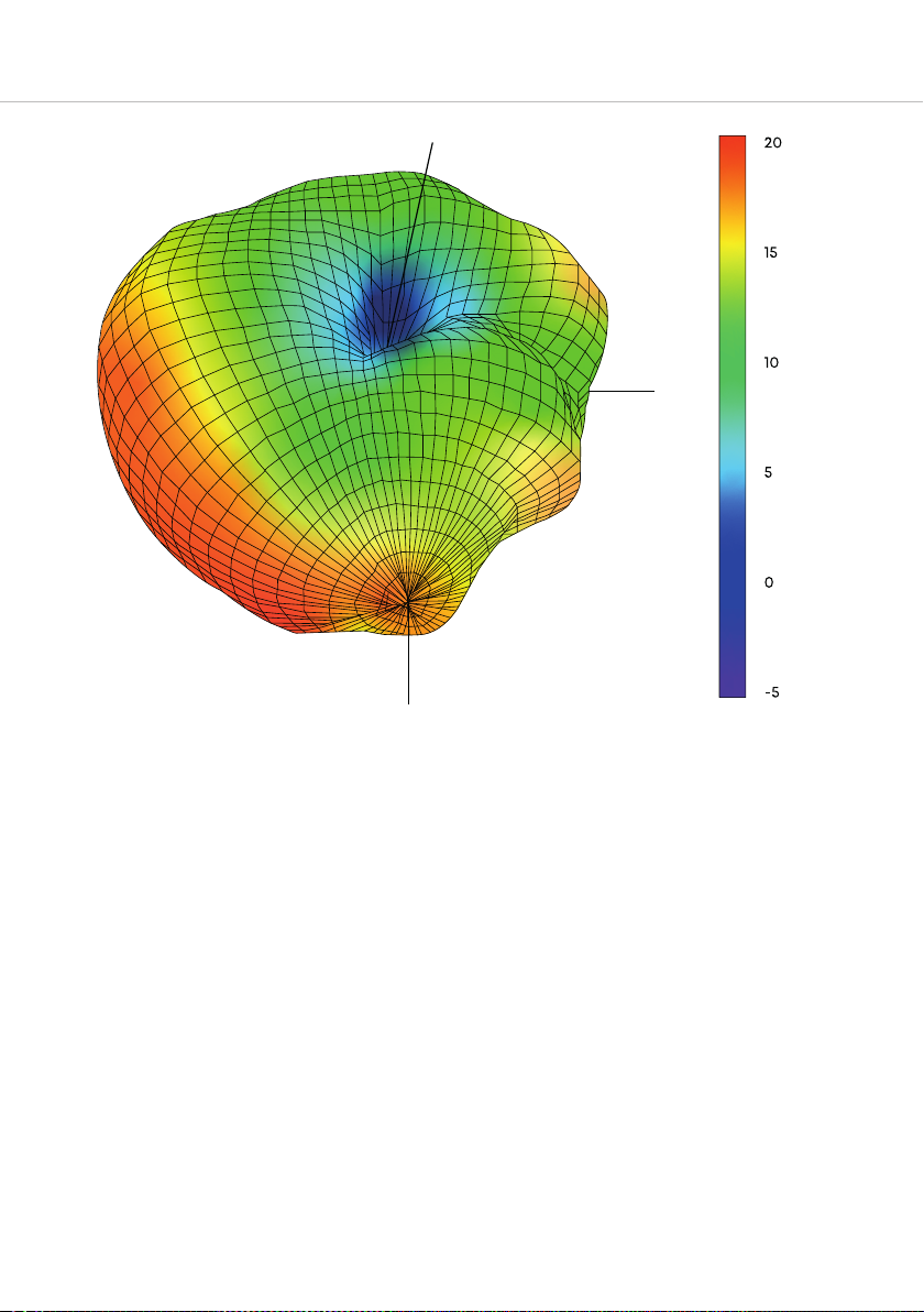
Azimuth = 7.4
Elevation = -43.6
Roll = 11.5
Power (dBm)
X
Z
Y
Unite AP4 – Access Point
3D polar pattern / 3D-Polardiagramm
Page 45

Page 46

Page 47

Page 48

English
Unite
Operating instructions
Unite
Landing page
Deutsch
Unite
Systemanleitung
Unite
Landing Page
www.beyerdynamic.com
beyerdynamic GmbH & Co. KG
Theresienraße 8 • 74072 Heilbronn • Germany
Phone +49 7131 617-300 • info@beyerdynamic.de
For fuher diributors worldwide, please go to www.beyerdynamic.com
Non-contractual illurations. Subject to change without notice.
Weitere Veriebspaner weltweit finden Sie im Internet unter www.beyerdynamic.com
Abbildungen nicht veragsbindend. Änderungen vorbehalten.
EN-DE 3 / Unite AP4 / 679.240 (09.19)
 Loading...