

Page 1

BEDIENUNGSANLEITUNG
OPERATING INSTRUCTIONS
NOTICE D’UTILISATION
MANUAL DEL USUARIO
Opus 900
Drahtloses UHF-System
Wireless UHF System
Système sans fil UHF
Sistema inalámbrico en UHF
Page 2

Page 3

3
INHALT / CONTENTS / SOMMAIRE
BEDIENUNGSANLEITUNG Opus 900
OPERATING INSTRUCTIONS Opus 900
NOTICE D’UTILISATION Opus 900
english deutschfrançais
Wichtige Sicherheitsinformationen . . . . . . . . . . . . . . . Seite 6
Diversityempfänger NE 900. . . . . . . . . . . . . . . . . . . . . Seite 8
Antennensplitter ZAS 800 . . . . . . . . . . . . . . . . . . . . . . Seite 16
Anschluss an einen PC . . . . . . . . . . . . . . . . . . . . . . . . Seite 18
NE 900 D Cobra – Bedienhinweise . . . . . . . . . . . . . . . Seite 19
Handsender S 900 C / S 900 M / S 900 P . . . . . . . . . . Seite 23
Taschensender TS 900. . . . . . . . . . . . . . . . . . . . . . . . . Seite 29
Hinweise für alle Sender . . . . . . . . . . . . . . . . . . . . . . . Seite 35
Fehlercheckliste. . . . . . . . . . . . . . . . . . . . . . . . . . . . . . Seite 36
Service . . . . . . . . . . . . . . . . . . . . . . . . . . . . . . . . . . . . Seite 37
Zulassung und Anmeldepflicht . . . . . . . . . . . . . . . . . . Seite 37
Komponenten. . . . . . . . . . . . . . . . . . . . . . . . . . . . . . . Seite 38
Zubehör - optional . . . . . . . . . . . . . . . . . . . . . . . . . . . Seite 39
Technische Daten . . . . . . . . . . . . . . . . . . . . . . . . . . . . Seite 40
Konformitätserklärung . . . . . . . . . . . . . . . . . . . . . . . . Seite 160
Important Safety Information . . . . . . . . . . . . . . . . . . . Page 44
NE 900 Diversity Receiver . . . . . . . . . . . . . . . . . . . . . . Page 48
ZAS 800 Antenna Splitter . . . . . . . . . . . . . . . . . . . . . . Page 56
Connection to a PC . . . . . . . . . . . . . . . . . . . . . . . . . . Page 58
NE 900 D Cobra – Operating Instructions . . . . . . . . . . Page 59
S 900 C / S 900 M / S 900 P Handheld Transmitters . . Page 63
TS 900 Beltpack Transmitter . . . . . . . . . . . . . . . . . . . . Page 69
General Instructions for all Transmitters . . . . . . . . . . . Page 75
Trouble Shooting. . . . . . . . . . . . . . . . . . . . . . . . . . . . . Page 76
Maintenance. . . . . . . . . . . . . . . . . . . . . . . . . . . . . . . . Page 77
Licensing. . . . . . . . . . . . . . . . . . . . . . . . . . . . . . . . . . . Page 77
Components. . . . . . . . . . . . . . . . . . . . . . . . . . . . . . . . Page 77
Optional Accessories . . . . . . . . . . . . . . . . . . . . . . . . . . Page 79
Technical Specifications . . . . . . . . . . . . . . . . . . . . . . . . Page 80
Declaration of Confirmity . . . . . . . . . . . . . . . . . . . . . . Page 160
Consignes de sécurité importants . . . . . . . . . . . . . . . . Page 84
Récepteur «Diversity» NE 900. . . . . . . . . . . . . . . . . . . Page 86
Splitter d’antenne ZAS 800. . . . . . . . . . . . . . . . . . . . . Page 94
Raccordement à un PC . . . . . . . . . . . . . . . . . . . . . . . . Page 96
NE 900 D Cobra – Instructions d’utilisation . . . . . . . . . Page 97
L’émetteur à main S 900 C / S 900 M / S 900 P . . . . . Page 101
L’émetteur de poche TS 900 . . . . . . . . . . . . . . . . . . . . Page 107
Remarques concernant tout type d’émetteur . . . . . . . . . Page 113
Dépannage . . . . . . . . . . . . . . . . . . . . . . . . . . . . . . . . . Page 114
Service après-vente . . . . . . . . . . . . . . . . . . . . . . . . . . . Page 115
Homologation. . . . . . . . . . . . . . . . . . . . . . . . . . . . . . . Page 115
Eléments. . . . . . . . . . . . . . . . . . . . . . . . . . . . . . . . . . . Page 116
Accessoires en option . . . . . . . . . . . . . . . . . . . . . . . . . Page 117
Spécifications techniques . . . . . . . . . . . . . . . . . . . . . . Page 118
Déclaration de conformité . . . . . . . . . . . . . . . . . . . . . Page 160
Page 4

Page 5

5
CONTENIDO
MANUAL DEL USUARIO Opus 900
español
Información Importante de seguridad . . . . . . . . . . . Página 122
NE 900 Receptor diversity . . . . . . . . . . . . . . . . . . . . Página 124
Splitter de antenas ZAS 800 . . . . . . . . . . . . . . . . . . Página 132
Conexión a un PC. . . . . . . . . . . . . . . . . . . . . . . . . . Página 134
NE 900 D Cobra – Indicaciones de manejo . . . . . . . Página 135
Transmisores de mano S 900 C / S 900 M / S 900 P . . Página 139
Transmisores de bolsillo TS 900 . . . . . . . . . . . . . . . . Página 145
Instrucciones generales para todos los
transmisores . . . . . . . . . . . . . . . . . . . . . . . . . . . . . . Página 151
Problemas . . . . . . . . . . . . . . . . . . . . . . . . . . . . . . . . Página 152
Mantenimiento . . . . . . . . . . . . . . . . . . . . . . . . . . . . Página 153
Licencias . . . . . . . . . . . . . . . . . . . . . . . . . . . . . . . . . Página 153
Componentes . . . . . . . . . . . . . . . . . . . . . . . . . . . . . Página 154
Accesorios opcionales . . . . . . . . . . . . . . . . . . . . . . . Página 155
Especificaciones técnicas . . . . . . . . . . . . . . . . . . . . . Página 156
Declaración de conformidad . . . . . . . . . . . . . . . . . . Página 160
Page 6

6
BEDIENUNGSANLEITUNG OPUS 900
Sie haben sich für das drahtlose Mikrofonsystem Opus 900 entschieden. Vielen Dank für Ihr
Vertrauen.
Nehmen Sie sich bitte einige Minuten Zeit und lesen Sie diese Bedienungsanleitung vor
Inbetriebnahme aufmerksam durch.
Wichtig:
• Überprüfen Sie die Geräte auf sichtbare Transportschäden. Wenn Sie Transportschäden feststellen,
wenden Sie sich umgehend an das zuständige Transportunternehmen. Bei verzögerter Meldung
von Transportschäden besteht die Gefahr, dass Ihre Rechtsansprüche ver lorengehen. Es ist ausschließlich der Empfänger berechtigt, Forderungen wegen Transport schäden einzureichen.
Empfänger
• LESEN Sie die Bedienungsanleitung.
• BEWAHREN Sie diese Bedienungsanleitung auf.
• BEFOLGEN Sie die aufgeführten Bedienungs- und Sicherheitshinweise.
• Das Gerät muss so aufgestellt werden, dass der Netzanschluss, Netzschalter und alle
Audioanschlüsse auf der Rückseite des Gerätes leicht zugänglich sind.
• Das Gerät muss an eine Netz-Steckdose mit Schutzkontakt angeschlossen werden.
• Setzen Sie das Gerät niemals Regen oder hoher Feuchtigkeit aus. Installieren Sie es daher nicht in
unmittelbarer Nähe von Swimming Pools, Duschanlagen, feuchten Kellerräumen oder sonstigen
Bereichen mit außergewöhnlich hoher Luftfeuchtigkeit.
• Stellen Sie niemals mit Flüssigkeiten gefüllte Gegenstände (z.B. Vasen oder Trinkgläser) auf das
Gerät. Flüssigkeiten in den Geräten können einen Kurzschluss verursachen.
• Reinigen Sie das Gerät nur mit einem leicht feuchten oder trockenem Tuch. Verwenden Sie niemals
Lösungsmittel, da diese die Oberfläche beschädigen.
• Installieren und betreiben Sie das Gerät auch niemals in unmittelbarer Nähe von Heizkörpern,
Beleuchtungsanlagen oder anderen wärmeerzeugenden Geräten.
• Verlegen Sie alle Kabel stets so, dass sie nicht durch scharfe Gegenstände geknickt oder gar durchgetrennt werden können.
• Verlegen Sie alle Anschlusskabel so, dass niemand darüber stolpern und sich verletzen kann.
• Schalten Sie bei allen Arbeiten an den Ein- und Ausgängen die Stromzufuhr aus.
• Überprüfen Sie, ob die Anschlusswerte mit der vorhandenen Netzstromversorgung über einstimmen. Bei Anschluss des Systems an die falsche Stromversorgung können ernsthafte Schäden
entstehen. Eine falsche Netzspannung kann das Gerät beschädigen oder einen elektrischen Schlag
verursachen.
• Dieses Gerät benötigt eine ausreichende Ventilation. Decken Sie die Lüftungsöffnungen nicht ab.
Wenn die Eigenwärme nicht abgeführt wird, kann das Gerät beschädigt oder brennbare
Materialien in unmittelbarer Nähe können entzündet werden. Achten Sie daher darauf, dass die
Luft durch die Lüftungsöffnungen frei zirkulieren kann und halten Sie brennbare Materialien fern.
• Stellen Sie niemals offene Brandquellen (z.B. Kerzen) auf das Gerät.
• Wenn Sie das Gerät an einen anderen Ort transportieren, achten Sie darauf, dass es ausreichend
gesichert ist und niemand durch ein eventuelles Herunterfallen oder Stoßen am Gerät verletzt
werden kann.
• Nehmen Sie das Gerät bei einem Gewitter oder wenn Sie es längere Zeit nicht benutzen, vom
Netz.
• Wenn durch das Gerät eine Sicherung defekt oder ein Kurzschluss verursacht wurde, nehmen Sie
es vom Netz und lassen Sie es überprüfen und reparieren.
Wichtige Sicherheitsinformationen
Page 7

deutsch
7
• Öffnen Sie nicht eigenmächtig das Gerät. Sie könnten einen elektrischen Schlag erleiden. Überlassen
Sie alle Servicearbeiten nur autorisiertem Fachpersonal.
• Fassen Sie das Netzkabel nicht mit nassen Händen an und an den Kontaktstiften sollte sich kein
Wasser oder Staub befinden. In beiden Fällen könnten Sie einen elektrischen Schlag erleiden.
• Das Netzkabel muss fest angeschlossen sein. Ist es lose, besteht Brandgefahr.
• Ziehen Sie das Netzkabel immer am Stecker vom Netz und/oder vom Gerät - niemals am Kabel.
Das Kabel könnte beschädigt werden und einen elektrischen Schlag oder Brand verursachen.
• Wenn das Netzkabel angeschlossen ist, bringen Sie das Gerät nicht mit anderen metallischen
Gegenständen in Berührung.
• Stecken Sie keine Gegenstände in die Lüftungs- und andere Öffnungen. Sie könnten das Gerät
beschädigen und/oder sich verletzen.
• Setzen Sie das Gerät nicht ein, wenn der Netzstecker beschädigt ist.
• Wird das Gerät in ein 19"-Rack eingebaut, achten Sie darauf dass der Netzanschluss, Netzschalter
und alle Audioanschlüsse auf der Rückseite des Gerätes leicht zugänglich sind.
• Wenn Sie einen Kopfhörer anschließen, achten Sie darauf, dass die Lautstärke (Volume) auf
Minimum gedreht ist. Regeln Sie die Lautstärke erst nach Aufsetzen des Hörers. Stellen Sie die
Lautstärke nicht zu hoch ein. Sie können Ihr Gehör dauerhaft schädigen.
Sender
• Schützen Sie den Sender vor Feuchtigkeit, Herunterfallen und Schlag. Sie könnten sich oder andere
verletzen bzw. den Sender beschädigen.
• Pusten Sie nicht in das Mikrofon. Bei einem Kondensatormikrofon können Sie den Wandler
beschädigen. Geben Sie einer Sprechprobe den Vorzug.
• Ansteckmikrofone sind zum Teil sehr klein. Beim versehentlichen Verschlucken besteht
Erstickungsgefahr. Halten Sie solche Mikrofone daher immer fern von Kleinkindern.
• Schalten Sie den Sender vor dem Laden bzw. Batteriewechsel unbedingt aus.
• Laden Sie den Sender nie mit normaler Batterie bestückt im Ladegerät auf. Der Sender könnte zerstört werden.
• Die handelsüblichen 9 V-Alkalinebatterien können Längentoleranzen von 2-3 mm haben. Achten
Sie daher beim Austausch der Batterie auf guten Kontakt.
• Von Zeit zu Zeit sollten Sie die Batteriekontakte mit einem mit Spiritus oder Alkohol befeuchtetem,
weichem Tuch reinigen.
• Wenn Sie den Sender für Wochen oder Monate nicht benutzen, entfernen Sie bitte Akku/Batterie.
Akkus/Batterien können nach längerem Nichtgebrauch auslaufen und Leiterbahnen und Bauteile
zerfressen. Eine Reparatur ist dann nicht mehr möglich. In
diesem Fall entfallen alle Garantieansprüche. Auch die Bezeichnung „Leak proof“ auf Akkus/
Batterien ist keine Garantie gegen Auslaufen.
• Nehmen Sie die Batterien/Akkus niemals auseinander. Die enthaltene Akkumulatorsäure schädigt
Haut und Kleidung.
• Werfen Sie verbrauchte Akkus/Batterien nicht in den Hausmüll, sondern geben Sie diese an den
örtlichen Sammelstellen ab.
Page 8
8
1. Diversityempfänger NE 900
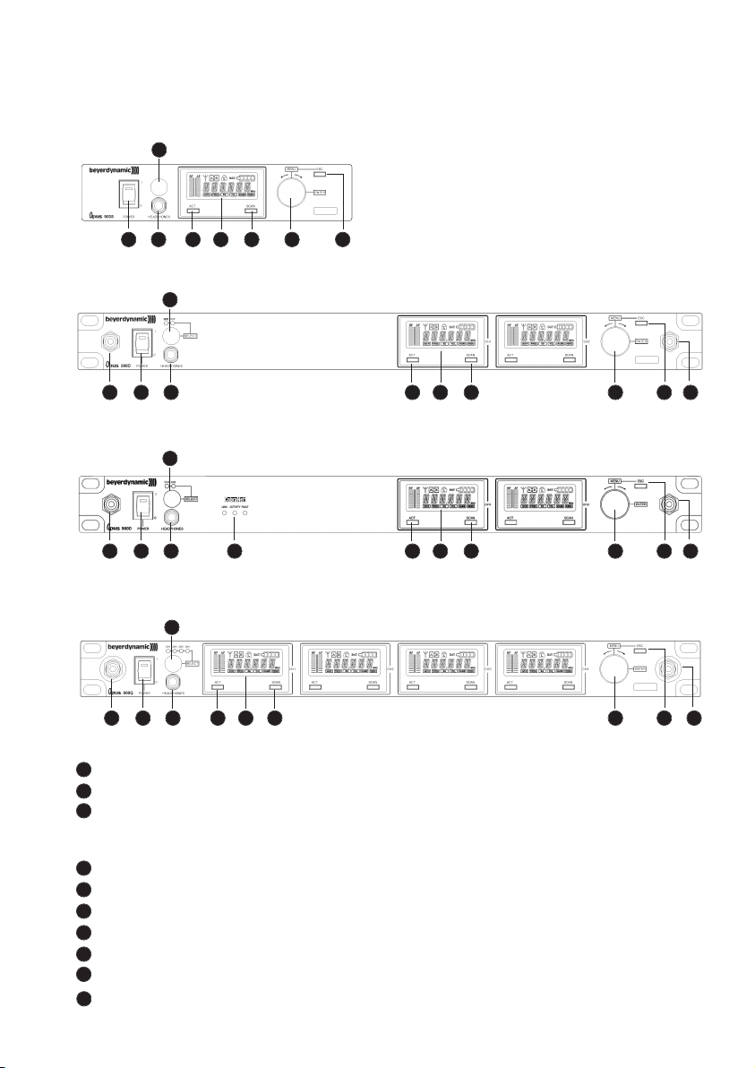
1.1 Bedien- und Kontrollelemente
Vorderseite NE 900 S
Netzschalter mit Betriebsanzeige
Kopfhörereingang
Lautstärkeregler für Kopfhörereingang zum Abhören einzelner Empfangskanäle.
NE 900 D / Q: Drücken Sie auf den Lautstärkeregler, um den gewünschten Empfangs kanal auszuwählen
Display
ACT-Taste
Scan-Taste
Menüregler (Auswahl und Einstellungen)
ESC-Taste
Antennenanschlussbuchse bei Frontmontage der Antennen
NE 900 D Cobra: CobraNet Status-LEDs LINK, ACTIVITY, FAULT
1
2
3
4
5
6
7
8
9
Vorderseite NE 900 D
Vorderseite NE 900 Q
10
1 2 5 4 6 7 8
3
3
3
1 2 5 4 6 7 8 99
Vorderseite NE 900 D Cobra
3
1 2 5 4 6 7 8 99
1 2 5 4 6 7 8 99
10
Page 9
deutsch
9
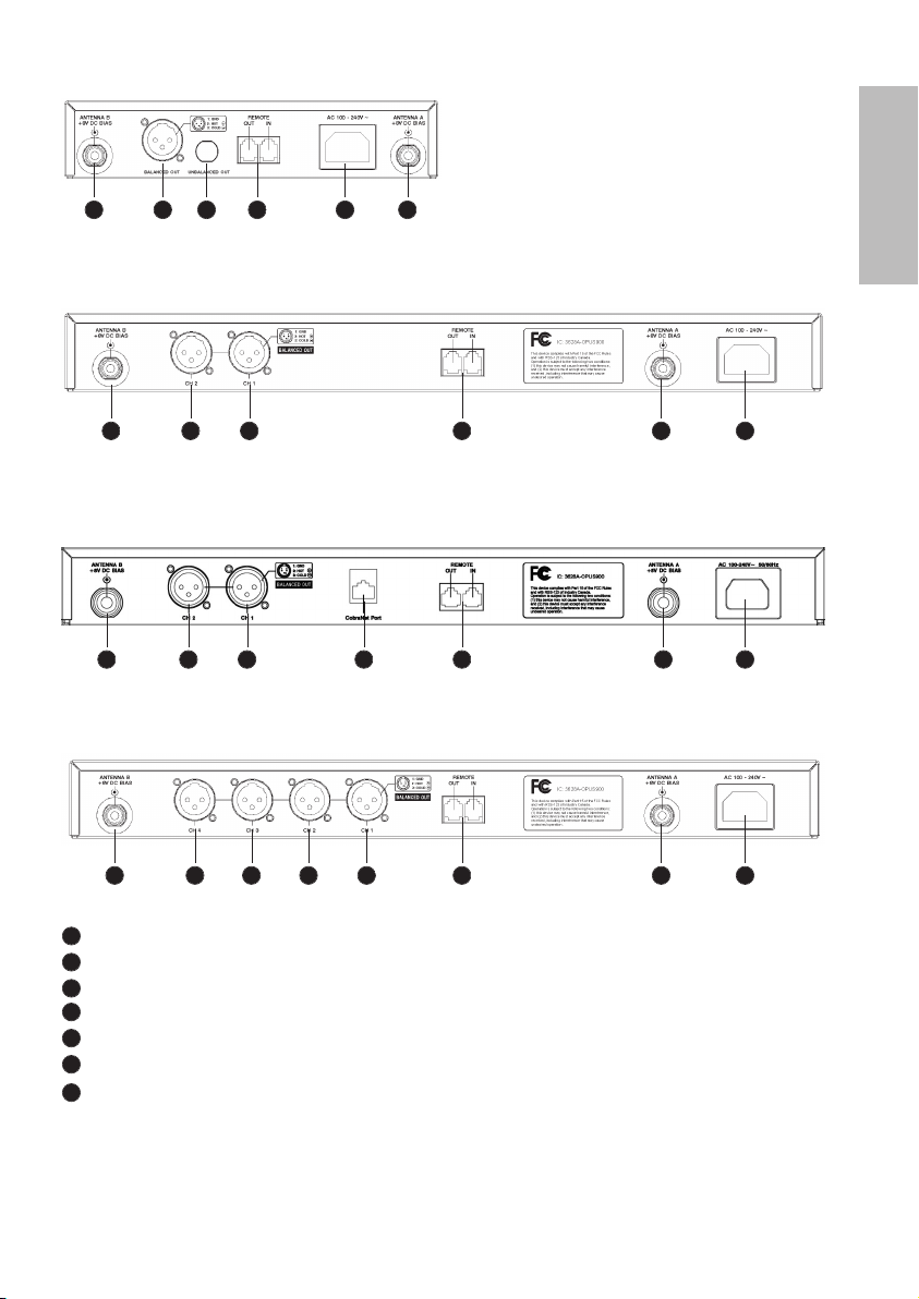
Antenneneingang B. TNC-Buchse. Mit Stromversorgung für Antennenverstärker
NF-Ausgang, 3-pol. XLR, symmetrisch
Remote-Anschluss IN / OUT
Antenneneingang A. TNC-Buchse. Mit Stromversorgung für Antennenverstärker
3-pol. Kaltgeräte-Netzanschluss
Nur bei NE 900 S: NF-Ausgang, 6,35 mm Klinke, unsymmetrisch
NE 900 D Cobra: CobraNet-Anschluss
Rückseite NE 900 D
Rückseite NE 900 S
Rückseite NE 900 Q
11
12
13
14
15
16
17
11 12 16 13 15 14
11 12 12 13 1514
Rückseite NE 900 D Cobra
11 12 12 1317 1514
11 12 12 12 12 13 1514
Page 10

10
1.2 Antennen anschließen
Schließen Sie die Antennen an die TNC-Buchsen und an und richten Sie sie nach schräg außen
aus (60° Winkel).
Für den Diversity-Betrieb müssen unbedingt beide Antennen angeschlossen sein! Eine Auswerteelektronik schaltet geräuschlos das jeweils bessere Antennensignal auf den Ausgang.
1.4 LC-Display und Menüeinstellungen
Auf dem LC-Display können Sie alle Betriebsparameter ablesen, wie z.B. HF- und NF-Pegel. Mit dem
Menüregler können Sie zwischen 6 Optionen wählen. Der aktivierte Menüpunkt wird durch einen
Rahmen im unteren Teil des Displays hervorgehoben.
Mit der ESC-Taste können Sie die Eingabe innerhalb des Menüs abbrechen. Die Eingaben werden
nicht übernommen und die ursprünglichen Einstellungen werden wieder angezeigt.
Um bei NE 900 D / Q die einzelnen Empfangsmodule für Menüeinstellungen auszuwählen, drücken
Sie solange auf den Menüregler , bis die grüne LED zwischen ACT- und SCAN-Taste blinkt. Drehen
Sie dann den Menüregler, um den gewünschen Empfangskanal auszuwählen. Die grüne LED am ausgewählten Empfangsmoduls blinkt. Drücken Sie den Menüregler zum Bestätigen. Die grüne LED
leuchtet dann dauernd.
Die Funktionen und die Bedienung werden im Folgenden beschrieben.
1.3 Inbetriebnahme
1. Stellen Sie den Diversityempfänger in dem Raum auf, in dem die Übertragung statt findet. Stellen
Sie den Empfänger so nahe wie möglich am Sender auf.
2. Stellen Sie den Diversityempfänger nicht neben digital gesteuerte Geräte.
3. Verbinden Sie den NF-Ausgang mit dem Mischpult- oder Verstärkereingang.
4. Schließen Sie das Gerät an der Netzsteckdose an.
5. Schalten Sie den Empfänger mit dem Netzschalter ein. Die rote Betriebsanzeige leuchtet.
6. Falls Sie den Empfänger als Tischgerät einsetzen, kleben Sie bitte auf die Unterseite die mitgelieferten Gummifüßchen, um eine ausreichende Luftzirkulation zu gewährleisten.
1411
1
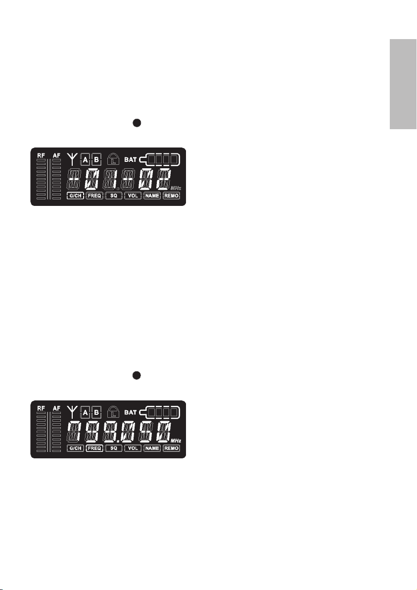
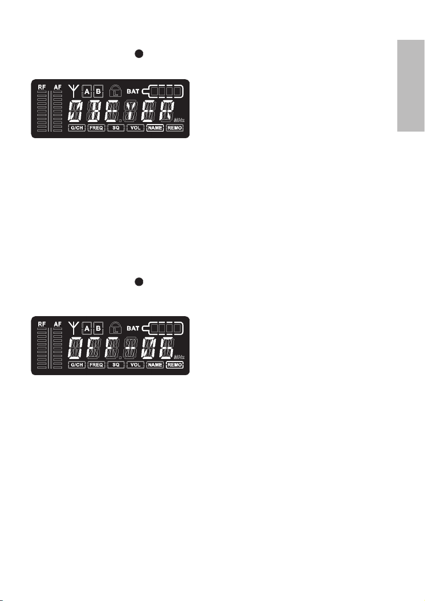
1.4.1 Diversity-Anzeige des Empfangskanals
Jedes Empfangsmodul enthält zwei getrennte Empfangsteile für die Antennen A und B. Auf das
jeweils stärker empfangene Signal wird automatisch umgeschaltet und dieses wei tergeleitet. Der
momentan aktive Diversity-Kanal wird im LC-Display angezeigt.
7
7
8
Page 11
deutsch
11
1.4.2 Ablesen des NF- und HF-Pegels
Im LC-Display können über Bargraphanzeigen der NF- und der HF-Pegel abgelesen werden.
1.4.3 Frequenzgruppe, Kanal
• Drehen Sie den Menüregler , bis „G/CH“ im Display durch einen Rahmen hervorgehoben ist. Sie
können nun die aktuell eingestellte Frequenzgruppe und Kanal ablesen.
• Wollen Sie die Einstellung verändern, drücken Sie auf den Menüregler. Die Ziffern für die
Frequenzgruppe fangen an zu blinken. Drehen Sie den Menüregler bis die gewünschte Gruppe
erscheint. Zum Bestätigen drücken Sie auf den Menüregler.
• Dann fängt die Ziffer für den Kanal an zu blinken. Drehen Sie wieder den Menüregler bis der
gewünschte Kanal erscheint. Zum Bestätigen drücken Sie auf den Menüregler.
• Mit der Scan-Taste können Sie automatisch einen anderen Kanal einstellen. Drücken Sie die
Scan-Taste ein Mal. Der Empfänger sucht automatisch einen störungsfreien Kanal innerhalb der
eingestellten Gruppe. Drücken Sie den Menüregler, um die Einstellung zu bestätigen.
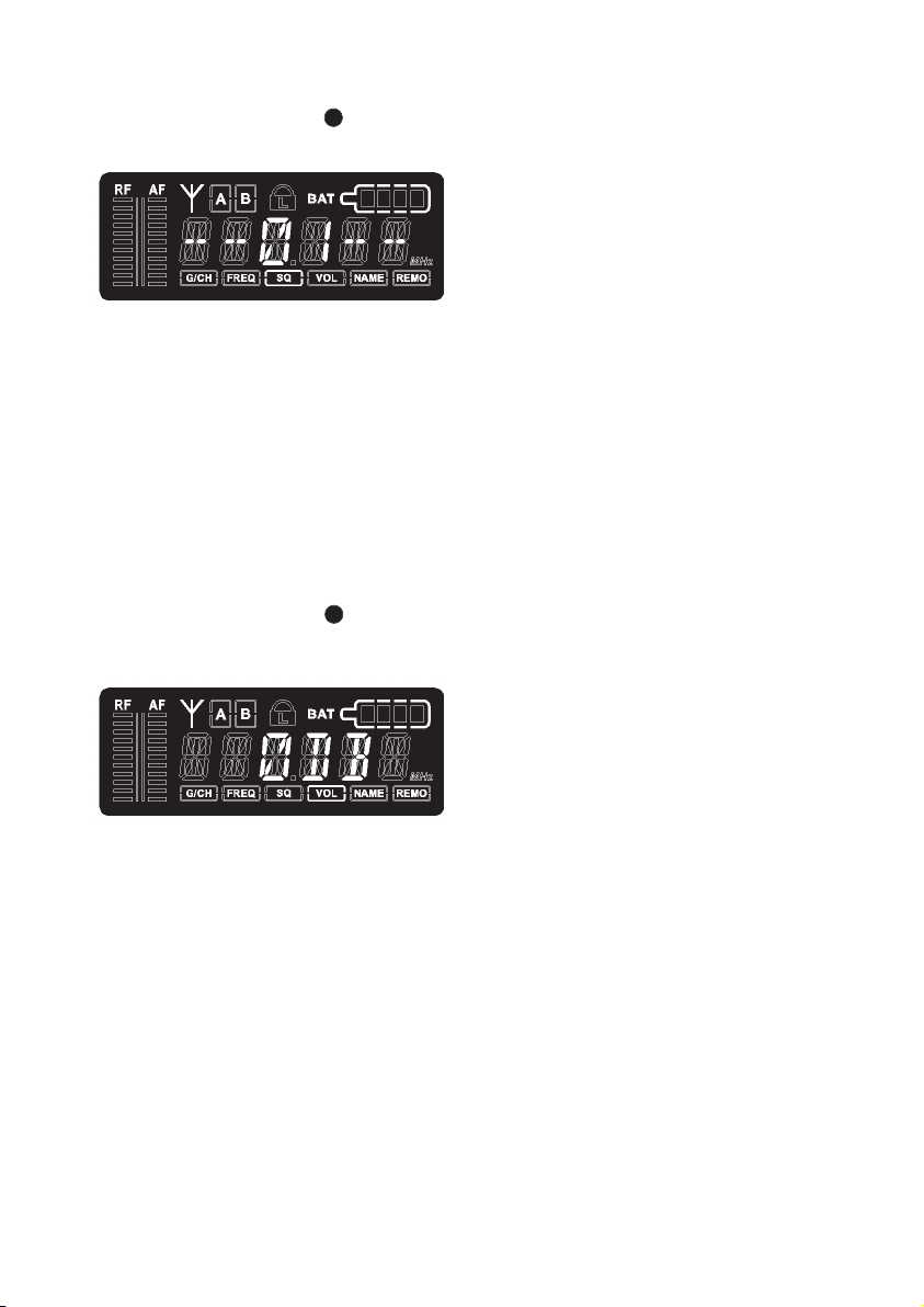
1.4.4 Frequenz ablesen und einstellen
• Drehen Sie den Menüregler , bis „FREQ“ im Display durch einen Rahmen hervorgehoben ist. Sie
können nun die aktuell eingestellte Frequenz ablesen.
• Wollen Sie die Einstellung verändern, drücken Sie auf den Menüregler. Die ersten drei Ziffern
(MHz - Stellen) blinken. Drehen Sie den Menüregler, um den gewünschten Wert einzustellen. Die
ersten drei Ziffern (MHz-Stellen) der Frequenz lassen sich in 1 MHz-Schritten verstellen. Zum
Bestätigen drücken Sie auf den Menüregler.
• Gleichzeitig fangen die letzten drei Ziffern (kHz-Stellen) an zu blinken. Drehen Sie den Menüregler,
um den gewünschten Wert einzustellen. Die letzten drei Ziffern (kHz-Stellen) lassen sich in
Schritten von 25kHz verstellen.
• Zum Bestätigen drücken Sie auf den Menüregler.
7
7
Page 12
12
1.4.5 Squelchpegel ablesen und einstellen
• Drehen Sie den Menüregler , bis „SQ“ im Display durch einen Rahmen hervorgehoben ist. Sie
können nun den aktuell eingestellten Squelchpegel ablesen.
• Wollen Sie den Squelchpegel verändern, drücken Sie auf den Menüregler. Der eingestellte Wert
blinkt. Drehen Sie den Menüregler, um den gewünschten Squelchpegel einzustellen. Dieser kann in
Schritten von 1 bis 99 eingestellt werden. Zum Bestätigen drücken Sie auf den Menüregler.
1.4.6 Ausgangspegel einstellen bzw. Stummschaltung
• Drehen Sie den Menüregler , bis „VOL“ im Display durch einen Rahmen hervorgehoben ist. Sie
können nun ablesen, ob der Empfänger stummgeschaltet oder ob der Ausgangspegel abgesenkt
ist.
• Wollen Sie die Einstellung verändern, drücken Sie auf den Menüregler. Die aktuelle Einstellung
blinkt.
• Drehen Sie den Menüregler, um den Empfänger stummzuschalten (MUTE) bzw. um den
Ausgangspegel analog zur Senderempfindlichkeit (0 dB, -10 dB, -20 dB, -30 dB) einzustellen.
• Drücken Sie den Menüregler, um die Einstellung zu bestätigen.
7
7
Page 13
deutsch
13
1.4.7 Name eingeben
• Drehen Sie den Menüregler , bis „NAME“ im Display durch einen Rahmen hervorgehoben ist.
Sie können einen evtl. bereits eingestellten Namen ablesen.
• Wollen Sie einen neuen Namen eingeben bzw. Änderungen vornehmen, drücken Sie den
Menüregler. Die erste Stelle blinkt. Drehen Sie den Menüregler bis der gewünschte Buchstabe, Zahl
oder Zeichen erscheint.
• Drücken Sie den Menüregler, um die Einstellung zu bestätigen und um die zweite Stelle eingeben
zu können. Wiederholen Sie diese Schritte so oft, bis Sie alle gewünschten Buchstaben, Zahlen
oder Zeichen eingegeben haben. Maximal können Sie 6 Zeichen / Symbole / Buchstaben eingeben.
1.4.8 Adressierung / Steuerung über PC
• Drehen Sie den Menüregler , bis „REMO“ im Display durch einen Rahmen hervorgehoben ist.
Am Display wird die Fernsteuer-Adresse und der Status der Fernsteuerung des jeweiligen Kanals
angezeigt.
• Um eine reibungslose Steuerung über PC zu gewährleisten, müssen die Empfangskanäle vor dem
Anschließen der Software unterschiedlich adressiert werden.
ACHTUNG:
Jede Fernsteuer-Adresse darf in einem Mehrkanalsystem nur einmal vergeben werden.
Wird ein Empfänger ohne PC-Steuerung betrieben, spielt es keine Rolle, ob zwei Kanäle die gleiche
Adresse haben.
• Bei Steuerung über PC erscheint im Display „ON“ und eine Zahl. Diese Zahl wird als Adresse
bezeichnet.
• Wird der Empfänger ohne PC betrieben, erscheint im Display „OFF“ und die Adresse.
• Zum Einstellen bzw. Ändern der Adresse drücken Sie den Menüregler. Die Zahl blinkt. Drehen Sie
den Menüregler, um die gewünschte Adresse einzustellen. Drücken Sie den Menüregler zum
Bestätigen.
7
7
Page 14
14
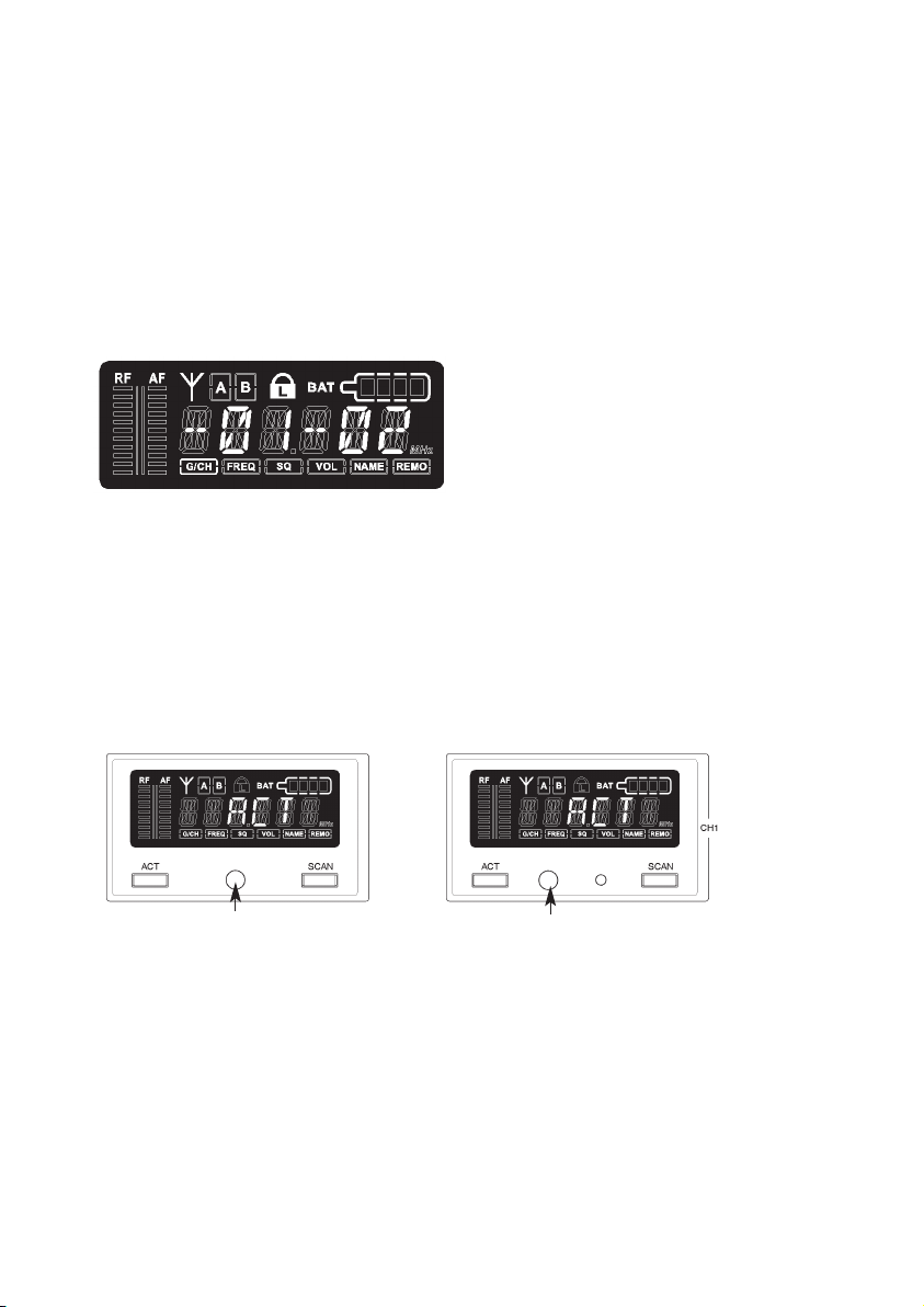
1.4.9 Sperrfunktion
Die Empfängerkanäle verfügen über eine Sperrfunktion, so dass ein versehentliches Verstellen der
Konfiguration verhindert werden kann.
Sperre einschalten
• Drücken Sie die ACT- und SCAN-Taste gleichzeitig.
• Im Display erscheint ein rotes Schloss-Symbol
• Nun sind außer der ACT-Taste alle Tasten gesperrt.
• Durch Drehen am Menüregler kann weiterhin die aktuelle Empfängerkanalkonfiguration abgelesen
werden.
• Die Sperrung bleibt auch nach einem Aus- und wieder Einschalten erhalten.
Sperre aufheben
• Drücken Sie die ACT- und SCAN-Taste gleichzeitig. Das rote Schloss-Symbol verschwindet.
1.5 Frequenzübertragung auf Sender (ACT-Funktion)
• Die eingestellte Frequenz des Empfangskanals wird per Infrarot auf den zugehörigen Sender übertragen.
• Drücken Sie die ACT-Taste, um die Funktion zu aktivieren. Im Display erscheint dann „ACT“.
• Halten Sie den eingeschalteten Sender mit dem Infrarotempfänger in einem Abstand von maximal
20 cm vor die Infrarotsendediode des Empfängers zwischen ACT- und SCAN-Taste.
• Im Display erscheint während der Programmierung „ACT“. Ist der Programmiervorgang beendet,
erscheint im Senderdisplay die eingestellte Gruppe/Kanal. Das Empfänger display springt auf den
Zustand vor dem Start der Programmierung zurück.
Wichtig:
Um Interferenzen/Störungen zu vermeiden, darf immer nur ein Sender auf einen Empfänger
programmiert werden.
NE 900 S NE 900 D / Q
Infrarotdiode
Infrarotdiode
Page 15
deutsch
15
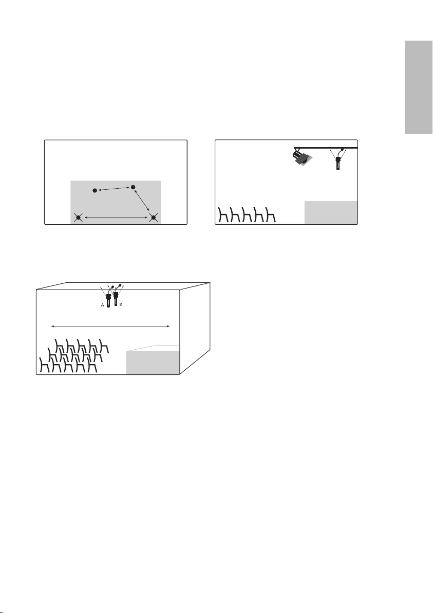
1.6 Anschließen und Aufstellen abgesetzter Antennen
Bei Mehrkanalanlagen empfehlen wir das UHF-Antennenset AT 70 A/B bestehend aus Antennen,
Antennenverstärker und Befestigungsvorrichtung.
1. Schließen Sie die Empfangsantennen an den entsprechenden Antennenein gängen an und stellen
Sie die Antennen rechts und links vom Aktionsbereich, in dem der Sender verwendet werden soll,
auf. Durch Positionsveränderung der Empfangsantennen kann der Empfang gegebenenfalls
verbessert werden.
2. Zwischen den Empfangsantennen sollte ein Mindestabstand von 1 m eingehalten werden.
3. Der Abstand zwischen Sender- und Empfangsantenne sollte mindestens 3 m betragen, um Übersteuerungen und somit Störungen zwischen den verschiedenen Kanälen zu vermeiden. Kann
dieser Abstand nicht eingehalten werden, empfehlen wir, insbesondere bei Mehrkanalsystemen,
die Empfangsantennen erhöht anzuordnen.
4. Beschränkt sich der Aktionsbereich der
Sender nicht nur auf die Bühne, können die
Emp fangs antennen auch senkrecht an der
Decke befestigt werden. Der Abstand
zwi schen beiden Emp fangs antennen sollte
ungefähr die Hälfte des gesamten Aktions bereiches betragen.
Bitte beachten Sie:
1. Installieren Sie die Empfangsantennen in dem Raum, in dem die Übertragung stattfindet.
2. Zur Vermeidung von Störungen, Empfangsantennen nicht neben digital gesteuerte Geräte stellen
oder an Beleuchtungsmasten befestigen (Brummeinstreuung).
3. Zu Metallobjekten, dazu gehören auch Stahlbetonwände, einen Mindestabstand von 50 cm
einhalten.
4. Antennenleitungen nicht zu stark abknicken, sondern bogenförmig zuführen. Antennenleitung
gegebenenfalls vor Zug mechanisch sichern.
> 1 m
> 3 m
> 1 m
AB
Bühne
Saal
Aktionsbereich des Senders
Bühne
Page 16
16
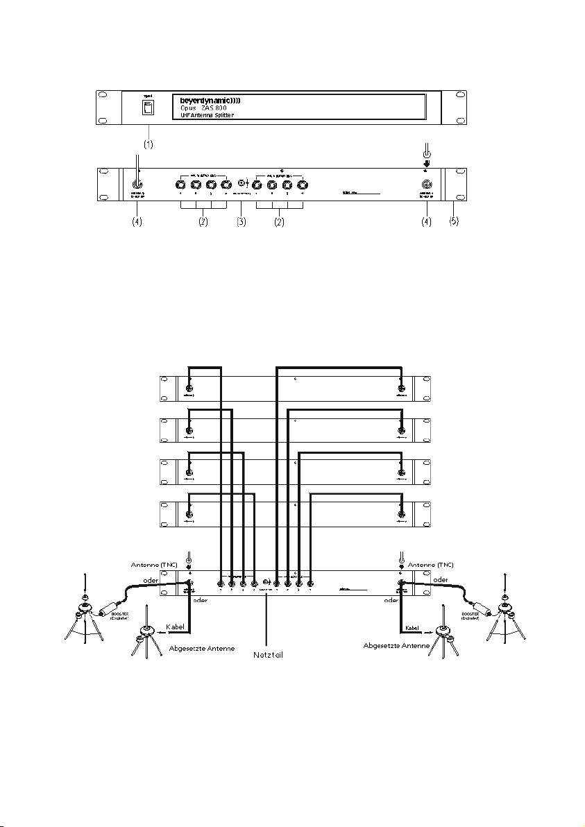
1.7 Antennensplitter ZAS 800
1.7.1 Bedienelemente und Funktionen
(1) Netzschalter und Betriebsanzeige. Wenn das Gerät eingeschaltet ist, leuchtet die rote Anzeige.
(2) HF-Ausgänge zum Anschluss der Empfänger
(3) Anschluss für 12V -Versorgung (DC)
(4) Antenneneingänge für A und B Antenne. Die Antenneneingänge sind mit einer
DC-Speisung für Antennenverstärker versehen. (DC 8V/170mA)
(5) Befestigungswinkel für Montage in ein 19"-Rack
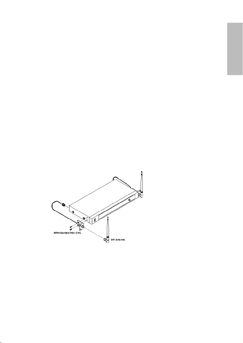
1.7.2 Installation
1. Montieren Sie den Antennensplitter ZAS 800 und die Empfänger mit den Befestigungswinkeln in
ein 19"-Rack.
2. Schließen Sie die mitgelieferten Antennen an den Antennenanschlüssen A/B (4) an. Als Antenne
können Sie auch abgesetzte Antennen (nicht im Lieferumfang enthalten) verwenden. Zur
Montage der Antennen auf der Vorderseite ist der Befestigungswinkel FB-30 im Lieferumfang
enthalten.
Erster Empfänger
Zweiter Empfänger
Dritter Empfänger
Vierter Empfänger
Page 17
deutsch
17
3. Verbinden Sie die Empfänger mit dem Antennensplitter ZAS 800 mit den mitgelieferten Kabeln.
4. Schließen Sie das Steckernetzteil am DC-Anschluss (3) an und verbinden Sie es mit einer
Steckdose. (Achtung: Überprüfen Sie vorher, ob die angegebene Netzspannung der orts üblichen
entspricht.).
5. Schalten Sie das Gerät mit dem Netzschalter (1) ein.
1.7.3 Allgemeine Hinweise
1. An den Antennenanschlüssen (4) liegt eine Spannung von 8 V DC an. Zur Vermeidung eines
Kurzschlusses sollten diese nicht mit dem Gehäuse des Racks in Berührung kommen.
2. Zum Anschluss von abgesetzten Antennen verwenden Sie normale 50Ω Koaxialkabel.
Je länger das Kabel, desto größer ist der HF-Signalverlust. Die Kabel sollten daher nicht länger als
6 m sein. Bei längeren Kabelwegen sollten dämpfungsarme Kabel verwendet werden und falls
notwendig Antennenverstärker.
3. Verwenden Sie 50Ω Koaxialkabel zum Anschluss der Empfänger an den Splitter ZAS 800. Der
Abstand zwischen den Geräten sollte so gering wie möglich sein. Benutzen Sie am besten die
mitgelieferten Kabel.
4. Lieferumfang:
8 x Kabel RG 58 AU, 40 cm lang (TNC)
1 Paar 19"-Rackwinkel inkl. Antennenfrontmontagekabel
1 x Netzteil
Page 18
18
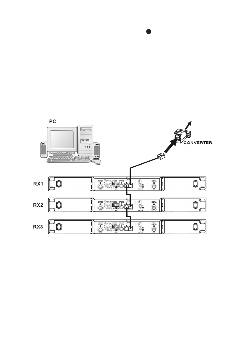
1.8 Anschluss an einen PC
Der NE 900 verfügt über einen Fernsteueranschluss (RJ 11) mit je einer IN- und OUT-Buchse. Für
den Betrieb mehrerer Empfänger mit einem PC müssen die Empfänger zunächst folgendermaßen miteinander verbunden werden.
• Verbinden Sie die OUT-Buchse des ersten Empfängers (RX 1) mit der IN-Buchse des zweiten
Empfängers (RX 2), die OUT-Buchse des zweiten Empfängers (RX 2) mit der IN-Buchse des dritten
Empfängers (RX 3) usw. bis alle Empfänger miteinander verbunden sind.
• Verbinden Sie die IN-Buchse des ersten Empfängers (RX 1) mit dem Converter.
• Schließen Sie den Converter an die USB-Schnittstelle des PC’s an.
• Mit der PC-Steuersoftware können maximal 64 Kanäle gleichzeitig betrieben werden.
• Die Entfernung zwischen PC und Empfänger sollte nicht zu groß sein, denn für eine optimale und
schnelle Übertragung sollte das Fernsteuerkabel nicht länger als 100 Meter sein.
USB PORT
RJ 11
12
Page 19
deutsch
19
1.9 NE 900 D Cobra – Bedienhinweise
Der NE 900 D Cobra verfügt über einen CobraNet-Anschluss , an welchen CobraNet-fähige Geräte
verschiedener Hersteller angeschlossen werden können. Nachfolgend finden Sie Bedienhinweise zum
NE 900 D Cobra.
1.9.1 Einstellen der CobraNet-Sendeadresse
1. Laden Sie die Software
„CobraNet Discovery Utility“ unter
www.cirrus.com/cobranetsoftware herunter.
2. Starten Sie das Programm und folgen Sie
den Installationshinweisen.
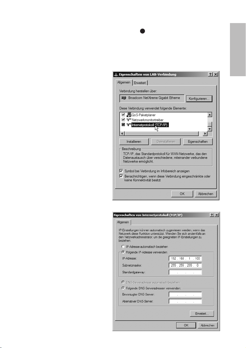
3. Öffnen Sie unter Systemsteuerung
-> Netzwerkverbindungen
-> LAN Verbindung die Eigenschaften
des Internetprotokolls (TCP/IP).
4. Wählen Sie „Folgende IP-Adresse
verwenden“ und geben Sie in das Feld
„IP-Adresse“, die IP-Adresse Ihres
Rechners mit 192.168.1.xxx ein. Die
Endnummer kann dabei zwischen 001
und 255 liegen.
Im Beispiel wurde die 100 verwendet.
Die Subnetmaske ist die 255.255.255.0.
17
Page 20
20
5. Öffnen Sie die Software „CobraNet
Discovery“ und verbinden Sie die
Netzwerkschnittstelle Ihres Rechners
mittels eines X-Over Cat.5 Kabels mit der
CobraNet Schnittstelle des
NE 900 D Cobra.
Schalten Sie den Empfänger
NE 900 D Cobra ein.
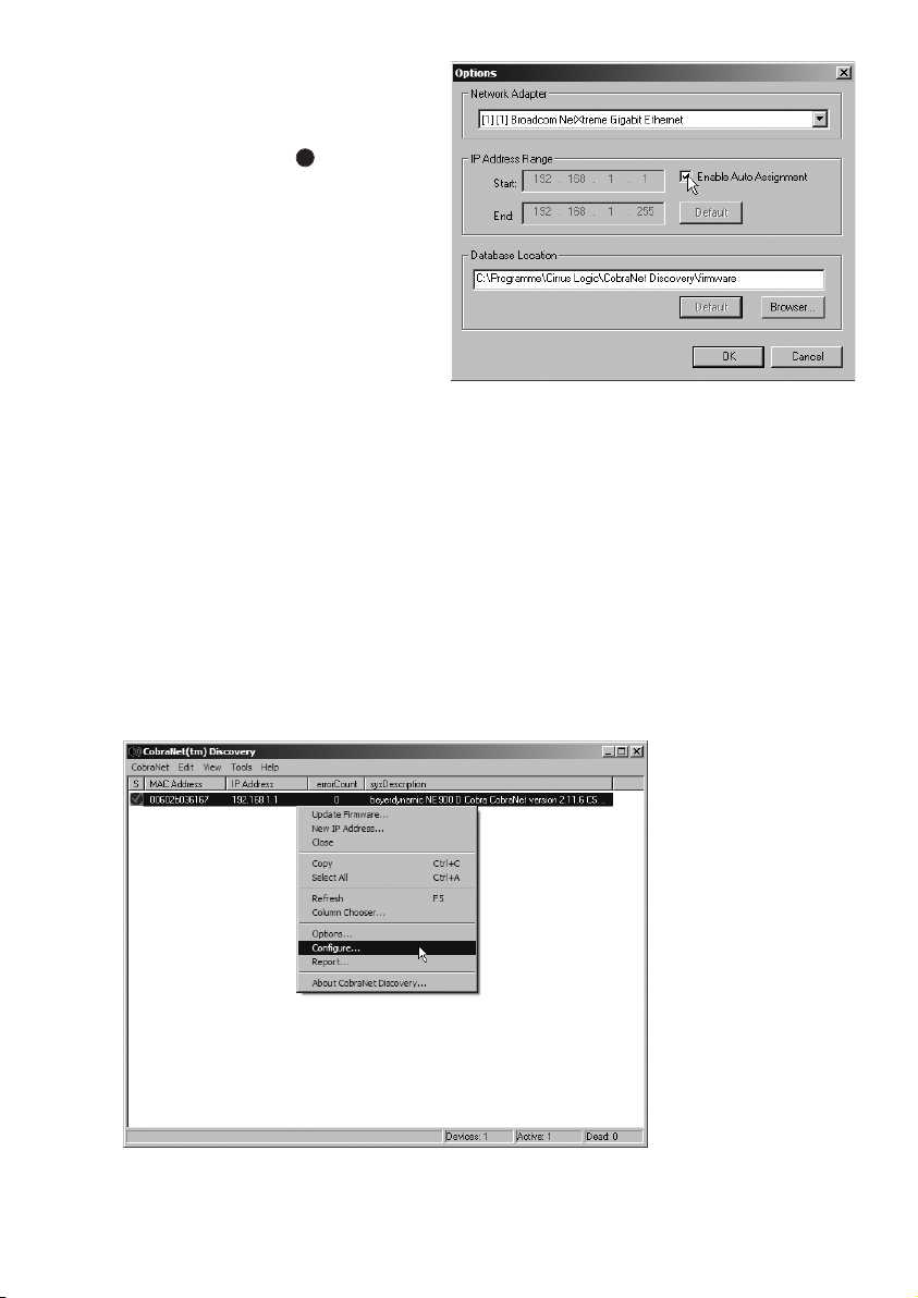
6. Unter Tools -> Options können Sie
Einstellungen an der Software vornehmen. Wählen Sie unter „Network
Adapter“ den Netzwerkadapter aus, an
den Sie den Empfänger angeschlossen
haben. Im Bereich „IP Address Range“
wählen Sie als Startadresse die
192.168.1.1 und als Endadresse die
192.168.1.255. Aktivieren Sie anschließend das Feld „Enable Auto
Assignment“ und klicken Sie auf „OK“.
7. In der Liste erscheint das CobraNet-Modul. Dem Modul wird automatisch eine IP-Adresse im
Bereich 192.168.1.xxx zugewiesen. Unter „sysDescription“ wird der beyerdynamic
NE 900 D Cobra erkannt. Die aktuelle Firmware Version wird ebenfalls angezeigt.
Wenn Sie mit der rechten Maustaste auf das Modul klicken, erscheint ein weiteres Menü, in
welchem Sie „Configure“ zum Parametrisieren des Empfängers anwählen können.
17
Page 21
deutsch
21
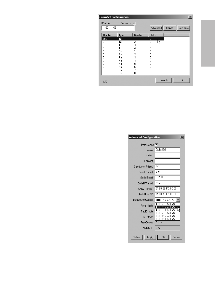
8. Im Auslieferungszustand sendet der
Empfänger NE 900 D Cobra immer auf
dem CobraNet Bundle 300.
Durch Anklicken des TX1 (Bundle
Number 300) und Anwählen der
Schaltfläche „Configure“ können Sie die
Bundle Number beliebig abändern.
9. Zum Ändern der CobraNet Latenz des Empfängers klicken
Sie unter „CobraNet Configuration“ auf das Feld
„Advanced“.
Unter dem Punkt „modeRate Control“ können Sie die
verschiedenen Latenzzeiten 1 1/3, 2 2/3 und 5 1/3 ms
anwählen.
Hinweis: Die Option 96 kHz SampleRate steht im
NE 900 D Cobra nicht zur Verfügung.
Page 22

22
1.9.2 NE 900 D Cobra Status LED-Anzeigen
Die CobraNet Status LEDs LINK, ACTIVITY und FAULT zeigen den Status der CobraNetNetzwerkverbindung an.
Die LINK-LED leuchtet nur, wenn das Ethernetkabel an ein Netzwerk mit anderen CobraNet-Geräten
angeschlossen ist.
Die ACTIVITY-LED leuchtet nur, wenn es eine Übereinstimmung gibt zwischen der Bitbreite/Latenz
und den Bundle-Einstellungen des NE 900 D Cobra sowie den Empfangsgeräten.
Die FAULT-LED zeigt dem Anwender mit einer Reihe von Blinkzeichen gefolgt von einer Pause einen
numerischen Code an.
Die Anzahl der Blinkzeichen bedeutet folgendes:
1. Falsch angepasstes Format oder Bundle-Einstellungen.
2. Nicht verwendet für NE 900 D Cobra.
3. Ungültige Bundle-Nummer ausgewählt (> 65279).
4. Ethernet-Kabel nicht angeschlossen bzw. kein anderes CobraNet-Gerät im Netzwerk.
5. CobraNet kann nicht mit der DSP im Empfänger NE 900 D Cobra kommunizieren.
10
Page 23
deutsch
23
2. Handsender S 900 C / S 900 M / S 900 P
2.1 Bedienelemente
Für den Handsender stehen verschiedene Kondensator und dynamische Mikrofon kapseln zur
Verfügung (siehe Zubehör optional).
Der Handsender S 900 C verfügt über Ladekontakte und kann nur mit dem integrierten Akkupack
betrieben werden. Vermeiden Sie einen direkten Kontakt der Ladekontakte mit der Haut; an den
Ladekontakten liegt eine Spannung von maximal 3 V an.
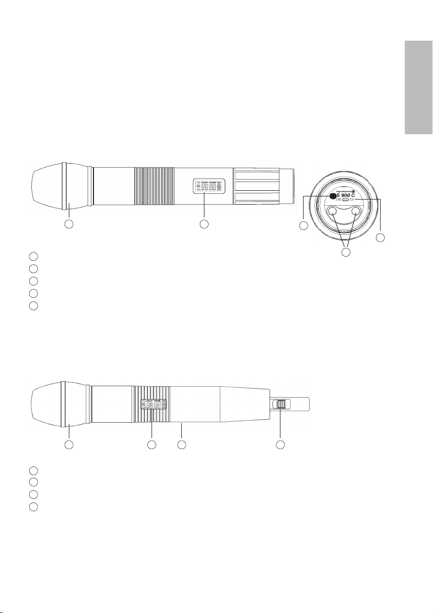
S 900 C
Mikrofonkopf (abschraubbar)
LC-Display
Infrarot-Diode (Unterseite)
Ein-/Ausschalter (Unterseite)
Ladekontakte (Unterseite nur bei S 900 C )
Mikrofonkopf (abschraubbar)
LC-Display
Infarot-Diode (auf Rückseite)
Ein-/Ausschalter
1
1
2
3
4
1
2
3
4
5
2
3
4
5
S 900 M / S 900 P
1 2 43
Page 24
24
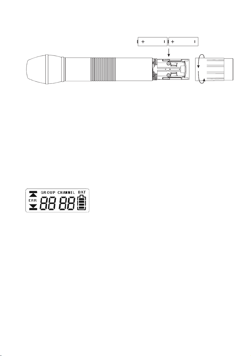
2.2 Einlegen der Batterie bei S 900 P und S 900 M
1. Schrauben Sie den Batteriefachdeckel bei S 900 P bzw. den Senderschaft bei S 900 M entgegen
dem Uhrzeigersinn ab.
2. Legen Sie die beiden Batterien (1,5 V) gemäß den Symbolen im Batteriefach ein.
Hinweis:
Der Sender S 900 C enthält Akkus, die nicht vom Anwender gewechselt werden können. Müssen die
Akkus gewechselt werden, wenden Sie sich bitte an Ihren beyerdynamic-Fachhändler.
2.3 Anzeigen im LC-Display
1. „ERR“-Meldung: Wenn im Display die Meldung „ERR“ erscheint, liegt ein Fehler vor.
ERR noo3: Frequenz oberhalb der Schaltbandbreite des Senders. Benutzen Sie einen zu dieser
Frequenzgruppe passenden Empfänger. (Zu diesem Zeitpunkt ist das Mikrofon noch funktionsfähig und die Frequenz bleibt unverändert. Um die Fehlermeldung im Display zu löschen, schalten
Sie den Handsender aus und wieder an.)
ERR noo4: Frequenz unterhalb der Schaltbandbreite des Senders. Benutzen Sie einen zu dieser
Frequenzgruppe passenden Empfänger. (Zu diesem Zeitpunkt ist das Mikrofon noch funktionsfähig und die Frequenz bleibt unverändert. Um die Fehlermeldung im Display zu löschen, schalten
Sie den Handsender aus und wieder an.)
2. „Group“ & „Channel“: Wenn beide Anzeigen im Display erscheinen, bedeutet das, dass Sie im
Moment die im Empfänger vorprogrammierten Frequenzen benutzen.
3. „Channel“: Wird im Display nur „Channel“ angezeigt, bedeutet das, dass Sie eine nicht vorpro-
grammierte Frequenz benutzen.
Page 25
deutsch
25
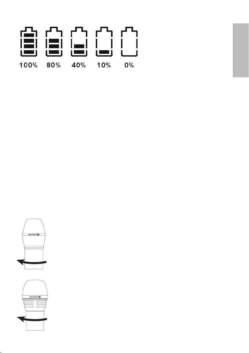
2.4 Batteriestatus
• Wenn die Batteriekapazität erschöpft ist, leuchtet die LED auf der Unterseite des Handsenders.
Ersetzen Sie die Batterie bzw. laden Sie die Akkus im Sender S 900 C auf. Im Display erscheint die
Meldung „PoFF“ und der Sender schaltet sich ab, falls die Batteriespannung zu niedrig ist.
2.5 Ausschalten des Handsenders
Wenn Sie den Ein-/Ausschalter auf der Unterseite des Handsenders in die „Off“-Position schalten,
erscheint im Display zuerst die Meldung „PoFF“. Sobald der Sender komplett abgeschaltet ist,
erscheint keine Meldung mehr im Display. Um den Sender unmittelbar wieder einschalten zu können,
ist eine Pause von ca. 1 Sekunde erforderlich.
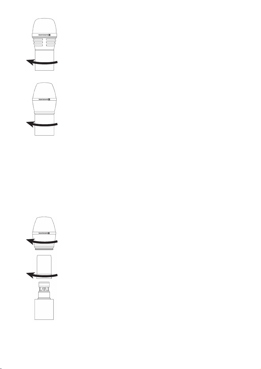
2.6 Mikrofonkopf wechseln
Für den Handsender sind verschiedene Mikrofonköpfe erhältlich. Wollen Sie einen Mikrofonkopf
wechseln, lösen Sie ihn vom Sender, indem Sie ihn nach links drehen. Setzen Sie den gewünschten
Mikrofonkopf auf und drehen ihn nach rechts, um ihn auf dem Sender zu fixieren.
CM 930
Echt-Kondensatormikrofonkopf, Nierencharakteristik, für Gesang und
Sprache. Für maximale Rückkopplungssicherheit. Gewicht 191 g.
DM 960
Dynamischer Mikrofonkopf, Hypernierencharakteristik, für Gesang sowie
Rundfunk und Fernsehen. Gewicht 191 g.
Page 26
26
2.7 Pflege
• Schützen Sie den Handsender vor Feuchtigkeit, Herunterfallen und Schlag.
• Zum Reinigen metallischer Oberflächen verwenden Sie ein mit Spiritus oder Alkohol befeuchtetes,
weiches Tuch.
• Sobald Sie Klangveränderungen feststellen, sollten Sie den integrierten Poppschutz reinigen.
Gehen Sie dabei wie nachfolgend beschrieben vor:
DM 969
Dynamischer Mikrofonkopf, Supernierencharakteristik, für Gesang.
Gewicht 131 g.
EM 981
Elektretkondensatormikrofonkopf, Nierencharakteristik,
für Vokalsolisten, Konferenzen und Ansprachen. Gewicht 191 g.
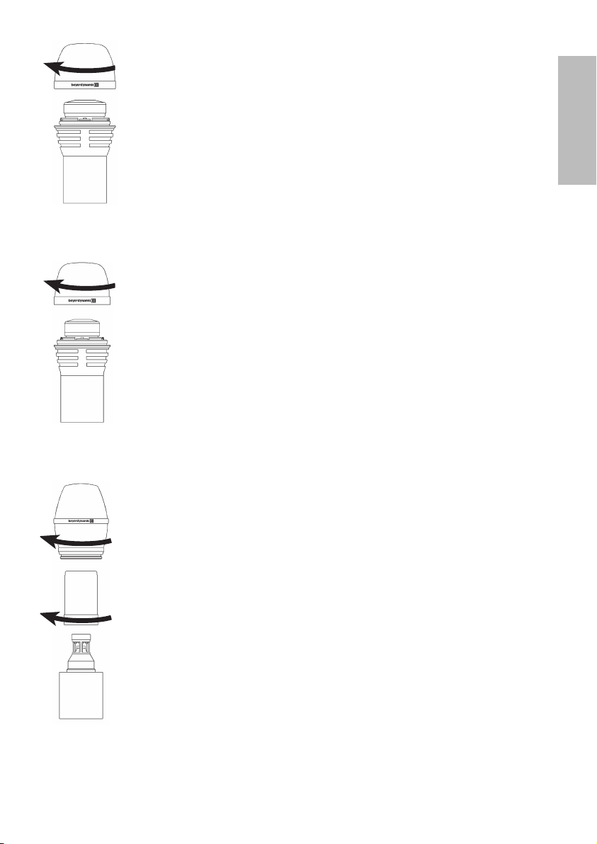
CM 930
• Schrauben Sie den Mikrofonkopf ab (nach links drehen).
• Schrauben Sie den Drahtpoppschutz ab (nach links drehen).
• Spülen Sie den Poppschutz unter klarem Wasser.
• Lassen Sie den Poppschutz über Nacht trocknen, bevor Sie ihn wieder
befestigen.
• Der Drahtpoppschutz ist nicht zur Reinigung in der Spülmaschine
geeignet.
Page 27
deutsch
27
DM 960
• Schrauben Sie den oberen Teil des Mikrofonkopfes ab (nach links
drehen).
• Spülen Sie ihn unter klarem Wasser.
• Lassen Sie den Poppschutz über Nacht trocknen, bevor Sie ihn wieder
befestigen.
• Der Oberkorb ist nicht zur Reinigung in der Spülmaschine geeignet.
EM 981
• Schrauben Sie den Mikrofonkopf ab (nach links drehen).
• Schrauben Sie den Drahtpoppschutz ab (nach links drehen).
• Spülen Sie den Poppschutz unter klarem Wasser.
• Lassen Sie den Poppschutz über Nacht trocknen, bevor Sie ihn wieder
befestigen.
• Der Drahtpoppschutz ist nicht zur Reinigung in der Spülmaschine
geeignet.
DM 969
• Schrauben Sie den oberen Teil des Mikrofonkopfes ab (nach links
drehen).
• Nehmen Sie den Schaumstoffpoppschutz heraus.
• Spülen Sie den Poppschutz unter klarem Wasser. Bei Bedarf können Sie
ein mildes Geschirrspülmittel verwenden.
• Fönen Sie den Poppschutz anschließend trocken oder lassen Sie ihn
über Nacht trocknen.
• Setzen Sie den trockenen Poppschutz wieder in den Mikrofonkorb und
schrauben Sie ihn im Uhrzeigersinn fest.
Page 28
28
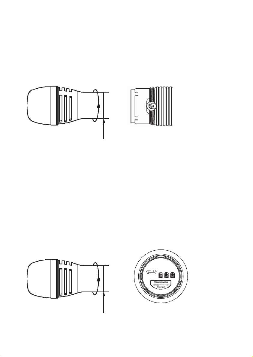
2.8 Einstellen der Empfindlichkeit am Handsender
• Zum Einstellen der Empfindlichkeit schrauben Sie den gesamten Mikro fon kopf in Pfeilrichtung ab.
• Mit einem Schraubendreher können Sie die gewünschte Empfindlichkeit (0 dB, 10 dB, 20 dB,
30 dB) einstellen.
• Niedrigste Empfindlichkeit = 0 dB
Höchste Empfindlichkeit = 30 dB
Mikrofonkopf abschrauben Empfindlichkeit einstellen
2.9 Schalten der Tiefenabsenkung
• Die Mikrofonköpfe CM 930 und EM 981 verfügen über eine schaltbare Tiefenabsenkung zur
Kompensation des bei Richtmikrofonen auftretenden Nahbesprechungseffekts. Zum Einstellen der
Tiefenabsenkung schrauben Sie den Mikro fon kopf in Pfeilrichtung ab.
• Auf der Unterseite des Mikrofonkopfes können Sie dann die Tiefenabsenkung hinzuschalten.
• Werkseinstellung: Linear (Position Lin)
Mikrofonkopf abschrauben Tiefenabsenkung schalten
Page 29
deutsch
29
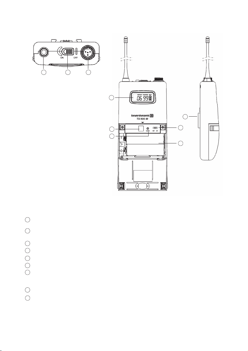
3. Taschensender TS 900
Der Taschensender TS 900 C verfügt über Ladekontakte und kann mit Akkus betrieben werden.
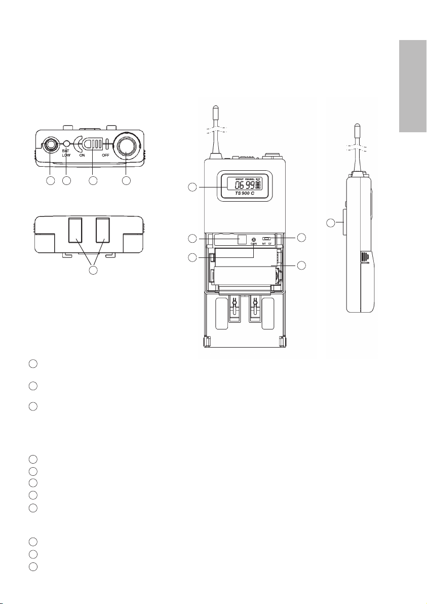
3.1 Bedienelemente
NF-Eingang, 4-pol. Mini-XLR-Anschluss für Mikrofone (Lavalier oder Nackenbügel). Die
Anschlussbelegung ist im Kapitel 3.5 „NF-Anschlussbelegung“ angegeben.
Ein-/Ausschalter (Ein = Schalter in „On“-Position; Aus = Schalter in „Off“-Position).
Schalten Sie den Sender immer aus, wenn Sie ihn nicht benutzen.
Nur bei TS 900 C: Batterieanzeige. Zeigt den Einschalt- und Batteriestatus an.
(a) Wenn der Taschensender eingeschaltet wird, blinkt die LED kurz auf und zeigt den normalen
Batteriestatus an.
(b) Leuchtet die rote LED nach dem Einschalten weiter, ist die Batterie zu schwach und muss
ersetzt bzw. der Akku aufgeladen werden.
Sendeantenne
LC-Display
Infrarotempfangsdiode für Frequenzübertragungsfunktion (ACT-Funktion)
Gain-Regler zum Einstellen der gewünschten Eingangsempfindlichkeit.
GT/MT-Schalter. Bei Betrieb mit elektrischer Gitarre Schalter auf die „GT“-Position
schalten. Der Gain-Regler ist im GT-Modus inaktiv. Schalter auf „MT“-Position für Kondensatorund drahtgebundene Mikrofone. Im MT-Modus ist der Gain-Regler aktiv.
Batteriefach für zwei 1,5 V (AA) Batterien bzw. Akkupack.
Nur bei TS 900 C: Ladekontakte
Abnehmbarer Gürtelclip kann um 360° gedreht werden. Zum Entfernen lösen Sie ihn
mit einem Schraubenzieher in einem Winkel von ca. 45°.
TS 900 C
1
5
234
6
7
8
9
11
10
1
2
3
4
5
6
7
8
9
10
11
Page 30
30
NF-Eingang, 4-pol. Mini-XLR-Anschluss für Mikrofone (Lavalier oder Nackenbügel).
Die Anschlussbelegung ist im Kapitel 3.5 „NF-Anschlussbelegung“ angegeben.
Ein-/Ausschalter (Ein = Schalter in „On“-Position; Aus = Schalter in „Off“-Position). Schalten Sie
den Sender immer aus, wenn Sie ihn nicht benutzen.
Sendeantenne
LC-Display
Infrarotempfangsdiode für Frequenzübertragungsfunktion
Gain-Regler zum Einstellen der gewünschten Eingangsempfindlichkeit.
GT/MT-Schalter. Bei Betrieb mit elektrischer Gitarre Schalter auf die „GT“-Position
schalten. Der Gain-Regler ist im GT-Modus inaktiv. Schalter auf „MT“-Position für
Kondensator- und drahtgebundene Mikrofone. Im MT-Modus ist der Gain-Regler aktiv.
Batteriefach für zwei 1,5 V (AA) Batterien.
Abnehmbarer Gürtelclip kann um 360° gedreht werden. Zum Entfernen lösen Sie ihn
mit einem Schraubenzieher in einem Winkel von ca. 45°.
TS 900 M
1
2
4
5
6
7
8
9
11
124
5
6
7
8
11
9
Page 31

deutsch
31
So entfernen Sie den Gürtelclip
3.2 Einlegen der Batterien / Akkus
1. Drücken Sie die beiden Schnappverschlüsse rechts und links am Batteriefach nach unten und
klappen Sie den Deckel auf. Entnehmen Sie die Batterien / Akkus. Siehe Abb. 1.
2. Legen Sie zwei 1,5 V Batterien bzw. das Akkupack gemäß den Symbolen auf dem
Batteriefachboden in das Batteriefach. Siehe Abb. 2. Der Akkupack ist mechanisch gegen
Verpolung gesichert. Schließen Sie den Batteriefachdeckel wieder.
Abb. 1 Abb. 2
Abb. 1 Abb. 2
Batterien einlegen TS 900 M
Akkupack einlegen TS 900 C
Page 32

32
3.3 Inbetriebnahme
1. Drücken Sie die beiden Schnappverschlüsse rechts und links am Batteriefach nach unten und
klappen Sie den Deckel auf, um den GT/MT-Schalter und die Eingangs empfind lichkeit
einzustellen.
2. Stellen Sie sicher, dass Sender und Empfänger auf der gleichen Frequenz arbeiten.
3. Beim TS 900 C blinkt die LED beim Einschalten kurz auf und zeigt den normalen Batteriestatus
an. Wenn die Anzeige nicht blinkt, fehlt die Batterie, sie ist ausgelaufen oder nicht richtig
eingelegt. Beim TS 900 M sehen Sie den Batteriestatus im LC-Display.
4. Schließen Sie das Mikrofon oder Instrument an die Eingangsbuchse an. Siehe hierzu auch
Abbildung unten.
8
7
1
3.4 Einpegelung des Senders
1. Schalten Sie den Taschensender TS 900 mit dem Ein-/Ausschalter ein. Stellen Sie den Gain-
Regler auf minimale Empfindlichkeit (Linksanschlag).
2. Zum Einpegeln sollte das Mikrofon mit dem zu erwartenden maximalen Pegel besprochen
werden. Geben Sie einem „U“-Laut den Vorzug, hierbei entsteht eine gute Sinusform. Stellen Sie
nun den Gain-Regler auf die gewünschte Emp find lich keit ein. Am Empfänger NE 900 darf der
AF-Pegel keine Übersteuerung anzeigen. Analoges gilt für die Abnahme von Instrumenten.
2
7
7
Page 33

deutsch
33
3.5 NF-Anschlussbelegung
(1) 2-adrige Elektret-Kondensator-Mikrofonkapsel
(2) 3-adrige Elektret-Kondensator-Mikrofonkapsel
(3) Dynamisches Mikrofon
(4) Elektrische Gitarre
(5) Line-Eingang (Impedanz 8 Ohm, Absenkung 10 dB)
z.B. Opus 54.18,
Opus 55.18,
Opus 56.18,
MCE 7.18
z.B. MCE 5.18,
MCE 10.18,
MCE 60.18
Page 34

34
3.6 Anzeigen im LC-Display
1. „ERR“-Meldung: Wenn im Display die Meldung „ERR“ erscheint, liegt ein Fehler vor.
ERR noo3: Frequenz oberhalb der Schaltbandbreite des Senders. Benutzen Sie einen zu dieser
Frequenzgruppe passenden Empfänger. (Zu diesem Zeitpunkt ist das Mikrofon noch funktionsfähig und die Frequenz bleibt unverändert. Um die Fehlermeldung im Display zu löschen, schalten
Sie den Sender aus und wieder an.)
ERR noo4: Frequenz unterhalb der Schaltbandbreite des Senders. Benutzen Sie einen zu dieser
Frequenzgruppe passenden Empfänger. (Zu diesem Zeitpunkt ist das Mikrofon noch funktionsfähig und die Frequenz bleibt unverändert. Um die Fehlermeldung im Display zu löschen, schalten
Sie den Sender aus und wieder an.)
2. „Group“ & „Channel“: Wenn beide Anzeigen im Display erscheinen, bedeutet das, dass Sie im
Moment die im Empfänger vorprogrammierten Frequenzen benutzen.
3. „Channel“: Wird im Display nur „Channel“ angezeigt, bedeutet das, dass Sie eine nicht vorpro-
grammierte Frequenz benutzen.
3.7 Batteriestatus
• Wenn die Batteriekapazität erschöpft ist, leuchtet die LED (nur bei TS 900 C). Ersetzen Sie die
Batterie. Im Display erscheint die Meldung „PoFF“ und der Sender schaltet sich ab, damit eine
Tiefentladung der Batterie vermieden wird.
3.8 Ausschalten des Taschensenders
Wenn Sie den Ein-/Ausschalter in die „Off“-Position schalten, erscheint im Display zuerst die Meldung
„PoFF“. Sobald der Sender komplett abgeschaltet ist, erscheint keine Meldung mehr im Display. Um
den Sender unmittelbar wieder einschalten zu können, ist eine Pause von ca. 1 Sekunde erforderlich.
3
Page 35

deutsch
35
4. Hinweise für alle Sender
4.1 Batteriewechsel
• Schalten Sie den Sender vor dem Batteriewechsel unbedingt aus.
• Wenn Sie den Sender für Wochen oder Monate nicht benutzen, entfernen Sie bitte Akku/
Batterie aus dem Sender. Akkus/Batterien können nach längerem Nichtgebrauch auslaufen und
Leiterbahnen und Bauteile zerfressen. Eine Reparatur ist dann nicht mehr möglich. In diesem Fall
entfallen alle Garantieansprüche. Auch die Bezeichnung „Leak proof“ auf Akkus/Batterien ist
keine Garantie gegen Auslaufen.
• Die Batteriekontakte sollten Sie von Zeit zu Zeit mit einem mit Spiritus oder Alkohol befeuchtetem, weichen Tuch reinigen.
• Werfen Sie verbrauchte Akkus/Batterien nicht in den Hausmüll, sondern geben Sie diese an den
örtlichen Sammelstellen ab.
• Zum Laden der Akkus verwenden Sie bitte nur beyerdynamic Ladegeräte.
4.2 Hinweise für den störungsfreien Betrieb
1. Überprüfen Sie den Ladezustand der Senderbatterie(n) und ersetzen Sie ggf. die Batterie(n).
Verwenden Sie nur neuwertige Alkalinebatterien.
2. Wenn die Sender aus- und sofort wieder eingeschaltet werden, kann es vorkommen, dass der
Sender ausgeschaltet bleibt. Ursache ist die Funktion, die ein knackfreies Ein- und Ausschalten
ermöglicht. Sollte dies während des Betriebs auftreten, kann es auch daran liegen, dass Batterien
Kontaktprobleme aufweisen. Nach dem Ausschalten sollte mindestens 1 Sekunde gewartet
werden, bevor der Sender wieder eingeschaltet wird.
3. Schreiten Sie den Bereich ab, in dem der Sender eingesetzt werden soll. Achten Sie dabei auf
Stellen, an denen die Feldstärke absinkt („Dropouts“) und der Empfang gestört ist. Solche
„Dropouts“ können Sie durch Verändern der Antennenposition (immer Sichtverbindung zu den
Sendern) beheben.
4. Stellen Sie die Empfangsantennen so auf, dass der Abstand zwischen Empfangsantenne und
Sender mindestens 3 m beträgt. Benutzen Sie evtl. abgesetzte Antennen (AT 70 A/B).
4.3 Positionierung von Sendern
Bei mehreren Frequenzen auf engstem Raum sollte das System auf Störungen hin überprüft werden.
Positionieren Sie alle Sender und schalten Sie sie ein. Danach schalten Sie jeden Sender einzeln aus
und überprüfen den Empfänger auf Störungen im jeweiligen Kanal.
Gegebenen
falls können Sie den Wert der Rauschsperre ändern, um die Störung herauszufiltern (siehe
auch Kapitel 1.4.5 Squelchpegel ablesen und einstellen).
Bei Mehrkanalbetrieb halten Sie bitte Rücksprache mit beyerdynamic. Störungen können auch durch
in der Nachbarschaft befindliche DVB-T-Fernsehsender entstehen.
Page 36

36
4.4 Tips gegen Rückkopplungen
Rückkopplungen treten dann auf, wenn Sie sich mit dem Mikrofon zu dicht am Lautsprecher befinden.
Wir empfehlen:
• Gehen Sie vom Lautsprecher weg.
• Drehen Sie das Mikrofon vom Lautsprecher weg.
5. Fehlercheckliste
5.1 Diversity-Empfänger NE 900
•
Stromversorgung unterbrochen,
Empfänger
ist nicht am Netz
angeschlossen
• Empfänger am Netz anschließen
•
Sender einschalten
• Stellen Sie die richtige Frequenz mit
der ACT-Funktion ein
• Überprüfen Sie die Verbindungskabel
bei abgesetzten Antennen
•
Eingangsverstärker des nachgeschalteten
Mixers ist übersteuert
• Absenkung am Mixer benutzen oder
mit Lautstärkeregler nachsteuern
Ton verzerrt
(Keine „CLIP“-Anzeige am
Empfänger)
Kein Empfang
Keine Funktion
Fehler Mögliche Ursache Lösung
• Sender ist nicht eingeschaltet
• Sender ist auf einer anderen Frequenz
• Verbindung bei abgesetzten Antennen ist
unterbrochen
„CLIP“-Anzeige am
Empfänger
•
Sender ist übersteuert
• Empfindlichkeit am Sender absenken
oder Mikrofon weiter von der Schallquelle entfernen
Kein Ton, RF-Anzeige ist
okay, AF-Anzeige fehlt
bei Modulation
•
Durch starke Störsignale falsche Anzeige
•
Kein Mikrofon am Taschensender TS 900
angeschlossen
• Frequenz wechseln
• Passendes Mikrofon anschließen
Page 37

deutsch
37
5.2 Hand- und Taschensender
• Sender und Empfänger haben nicht
dieselbe Frequenz
• Ungenügende Batterie spannung
•
Unzureichender Batteriekontakt, Batterie
falsch eingelegt
• Überprüfen Sie vor dem Einsatz, ob
die Frequenz von Sender und
Empfänger übereinstimmen
• Wechseln Sie die Batte
rie aus bzw.
laden Sie den
Akku wieder auf
•
Überprüfen Sie die Batte
rie und legen
Sie sie ggf. neu ein
•
Abstand zwischen Sender
und Empfänger
zu groß
• Verringern Sie den Abstand zwischen
Sender und Empfänger
Keine HF-Feldstärke (RF)
am Empfänger
•
Interferenzstörung durch
weitere Sender
• Zwei Sender auf derselben
Frequenz
• Batterie vom Sender zu schwach
• Schalten Sie die anderen Sender aus
• Wechseln Sie die Frequenz eines
Senders
• Wechseln Sie die Batterie,
bzw. laden
Sie den Akku wieder auf
Störgeräusche/
„Zwitschern“, starkes
Rauschen
Keine Funktion
Fehler Mögliche Ursache Lösung
6. Service
Im Servicefall wenden Sie sich bitte an autorisiertes Fach personal. Öffnen Sie das Gerät auf keinen
Fall selbst, Sie könnten sonst alle Garantieansprüche verlieren.
7. Zulassung und Anmeldepflicht
Um einen möglichst störungsfreien Betrieb mit anderen Funkdiensten (z.B. Fernsehen und Radio) zu
ermöglichen, werden drahtlosen Mikrofonen und Funkkopf hörern bestimmte Frequenzen und
Sendeleistungen zugeteilt.
In Deutschland ist dafür die Außenstelle der Bundesnetzagentur (www.bundesnetzagentur.de) zuständig.
Wichtig:
Drahtlos-Systeme benötigen eine Sendelizenz und sind anmelde- und gebührenpflichtig.
Lizenzpflichtig und damit kostenpflichtig sind in Deutschland alle Funkmikrofone im Bereich
470 – 862 MHz.
Ausnahmen:
Lizenzfrei (kostenlos) aufgrund einer gesetzlichen Allgemeinzuteilung sind die Geräte im Bereich
863-865MHz (sog. ISM-Frequenzen).
Neu ab 1.1.2006 in Deutschland:
Lizenzfrei sind Drahtlosmikrofone in den TV-Kanälen 61-63 (790-814MHz) und 67-69 (838-862MHz).
Die Komponenten des Opus 900 Systems sind gemäß Richtlinie R&TTE 99/5/EEC wie folgt zugelassen:
TS 900 M, TS 900 C
SDM 960 M, SCM 934 M, SDM 960, SDM 969, SDM 969 C, SEM 981 C
unter der Kennzeichnung CE 0682 !
Page 38

38
8. Komponenten
Empfänger
NE 900 Q 4-Kanal-True-Diversityempfänger, 668 - 692 MHz . . . . . . . . . . . Best.-Nr. 489.972
NE 900 Q dito, jedoch 774 - 798 MHz . . . . . . . . . . . . . . . . . . . . . . . . . . . Best.-Nr. 489.980
NE 900 Q dito, jedoch 790 - 814 MHz . . . . . . . . . . . . . . . . . . . . . . . . . . . Best.-Nr. 489.999
NE 900 Q dito, jedoch 841 - 865 MHz . . . . . . . . . . . . . . . . . . . . . . . . . . . Best.-Nr. 490.008
NE 900 D 2-Kanal-True-Diversityempfänger, 668 - 692 MHz . . . . . . . . . . . Best.-Nr. 490.016
NE 900 D dito, jedoch 774 - 798 MHz . . . . . . . . . . . . . . . . . . . . . . . . . . . Best.-Nr. 490.024
NE 900 D dito, jedoch 790 - 814 MHz . . . . . . . . . . . . . . . . . . . . . . . . . . . Best.-Nr. 490.032
NE 900 D dito, jedoch 841 - 865 MHz . . . . . . . . . . . . . . . . . . . . . . . . . . . Best.-Nr. 490.040
NE 900 D Cobra 2-Kanal-True-Diversityempfänger,
mit CobraNet-Schnittstelle, 668 - 692 MHz . . . . . . . . . . . . . . . Best.-Nr. 488.232
NE 900 D Cobra dito, jedoch 774 - 798 MHz . . . . . . . . . . . . . . . . . . . . . . . . . . . Best.-Nr. 488.240
NE 900 D Cobra dito, jedoch 790 - 814 MHz . . . . . . . . . . . . . . . . . . . . . . . . . . . Best.-Nr. 488.259
NE 900 D Cobra dito, jedoch 841 - 865 MHz . . . . . . . . . . . . . . . . . . . . . . . . . . . Best.-Nr. 488.267
NE 900 S 1-Kanal-True-Diversityempfänger, 668 - 692 MHz . . . . . . . . . . . Best.-Nr. 490.059
NE 900 S dito, jedoch 774 - 798 MHz . . . . . . . . . . . . . . . . . . . . . . . . . . . Best.-Nr. 490.067
NE 900 S dito, jedoch 790 - 814 MHz . . . . . . . . . . . . . . . . . . . . . . . . . . . Best.-Nr. 490.075
NE 900 S dito, jedoch 841 - 865 MHz . . . . . . . . . . . . . . . . . . . . . . . . . . . Best.-Nr. 490.083
Handsender
SDM 960 M UHF-Handsender, Metallgehäuse,
DM 960 Mikrofonkapsel, 668 - 692 MHz . . . . . . . . . . . . . . . . . Best.-Nr. 490.091
SDM 960 M dito, jedoch 774 - 798 MHz . . . . . . . . . . . . . . . . . . . . . . . . . . . Best.-Nr. 490.105
SDM 960 M dito, jedoch 790 - 814 MHz . . . . . . . . . . . . . . . . . . . . . . . . . . . Best.-Nr. 490.113
SDM 960 M dito, jedoch 841 - 865 MHz . . . . . . . . . . . . . . . . . . . . . . . . . . . Best.-Nr. 490.121
SCM 930 M UHF Handsender, Metallgehäuse,
CM 930 Mikrofonkapsel, 668 - 692 MHz . . . . . . . . . . . . . . . . . Best.-Nr. 490.148
SCM 930 M dito, jedoch 774 - 798 MHz . . . . . . . . . . . . . . . . . . . . . . . . . . . Best.-Nr. 490.156
SCM 930 M dito, jedoch 790 - 814 MHz . . . . . . . . . . . . . . . . . . . . . . . . . . . Best.-Nr. 490.164
SCM 930 M dito, jedoch 841 - 865 MHz . . . . . . . . . . . . . . . . . . . . . . . . . . . Best.-Nr. 490.172
SDM 960 UHF-Handsender, Kunststoffgehäuse,
DM 960 Mikrofonkapsel, 668 - 692 MHz . . . . . . . . . . . . . . . . . Best.-Nr. 490.180
SDM 960 dito, jedoch 774 - 798 MHz . . . . . . . . . . . . . . . . . . . . . . . . . . . Best.-Nr. 490.199
SDM 960 dito, jedoch 790 - 814 MHz . . . . . . . . . . . . . . . . . . . . . . . . . . . Best.-Nr. 490.202
SDM 960 dito, jedoch 841 - 865 MHz . . . . . . . . . . . . . . . . . . . . . . . . . . . Best.-Nr. 490.210
SDM 969 UHF-Handsender, Kunststoffgehäuse,
DM 969 Mikrofonkapsel, 668 - 692 MHz . . . . . . . . . . . . . . . . . Best.-Nr. 490.229
SDM 969 dito, jedoch 774 - 798 MHz . . . . . . . . . . . . . . . . . . . . . . . . . . . Best.-Nr. 490.237
SDM 969 dito, jedoch 790 - 814 MHz . . . . . . . . . . . . . . . . . . . . . . . . . . . Best.-Nr. 490.245
SDM 969 dito, jedoch 841 - 865 MHz . . . . . . . . . . . . . . . . . . . . . . . . . . . Best.-Nr. 490.253
SDM 969 C wie SDM 969 jedoch mit Ladekontakten,
668 - 692 MHz. . . . . . . . . . . . . . . . . . . . . . . . . . . . . . . . . . . . . Best.-Nr. 490.326
SDM 969 C dito, jedoch 774 - 798 MHz . . . . . . . . . . . . . . . . . . . . . . . . . . . Best.-Nr. 490.334
SDM 969 C dito, jedoch 790 - 814 MHz . . . . . . . . . . . . . . . . . . . . . . . . . . . Best.-Nr. 490.342
SDM 969 C dito, jedoch 841 - 865 MHz . . . . . . . . . . . . . . . . . . . . . . . . . . . Best.-Nr. 490.350
SEM 981 C UHF-Handsender, Kunststoffgehäuse,
EM 981 Mikrofonkapsel,
mit Ladekontakten, 668 - 692 MHz . . . . . . . . . . . . . . . . . . . . . Best.-Nr. 490.369
SEM 981 C dito, jedoch 774 - 798 MHz . . . . . . . . . . . . . . . . . . . . . . . . . . . Best.-Nr. 490.377
SEM 981 C dito, jedoch 790 - 814 MHz . . . . . . . . . . . . . . . . . . . . . . . . . . . Best.-Nr. 490.385
SEM 981 C dito, jedoch 841 - 865 MHz . . . . . . . . . . . . . . . . . . . . . . . . . . . Best.-Nr. 490.393
Page 39

deutsch
39
S 900 C UHF-Handsender, Kunststoffgehäuse, schwarz,
mit Ladekontakten, 668 - 692 MHz . . . . . . . . . . . . . . . . . . . . . Best.-Nr. 490.601
S 900 C dito, jedoch 774 - 798 MHz . . . . . . . . . . . . . . . . . . . . . . . . . . . Best.-Nr. 490.628
S 900 C dito, jedoch 790 - 814 MHz . . . . . . . . . . . . . . . . . . . . . . . . . . . Best.-Nr. 490.636
S 900 C dito, jedoch 841 - 865 MHz . . . . . . . . . . . . . . . . . . . . . . . . . . . Best.-Nr. 490.644
S 900 M UHF-Handsender, Metallgehäuse, schwarz,
668 - 692 MHz. . . . . . . . . . . . . . . . . . . . . . . . . . . . . . . . . . . . . Best.-Nr. 490.555
S 900 M dito, jedoch 774 - 798 MHz . . . . . . . . . . . . . . . . . . . . . . . . . . . Best.-Nr. 490.563
S 900 M dito, jedoch 790 - 814 MHz . . . . . . . . . . . . . . . . . . . . . . . . . . . Best.-Nr. 490.571
S 900 M dito, jedoch 841 - 865 MHz . . . . . . . . . . . . . . . . . . . . . . . . . . . Best.-Nr. 490.598
S 900 P UHF-Handsender, Kunststoffgehäuse, schwarz,
668 - 692 MHz. . . . . . . . . . . . . . . . . . . . . . . . . . . . . . . . . . . . . Best.-Nr. 498.661
S 900 P dito, jedoch 774 - 798 MHz . . . . . . . . . . . . . . . . . . . . . . . . . . . Best.-Nr. 498.688
S 900 P dito, jedoch 790 - 814 MHz . . . . . . . . . . . . . . . . . . . . . . . . . . . Best.-Nr. 498.696
S 900 P dito, jedoch 841 - 865 MHz . . . . . . . . . . . . . . . . . . . . . . . . . . . Best.-Nr. 498.718
Taschensender
TS 900 M UHF-Taschensender, Metallgehäuse, 668 - 692 MHz . . . . . . . . . Best.-Nr. 490.407
TS 900 M dito, jedoch 774 - 798 MHz . . . . . . . . . . . . . . . . . . . . . . . . . . . Best.-Nr. 490.415
TS 900 M dito, jedoch 790 - 814 MHz . . . . . . . . . . . . . . . . . . . . . . . . . . . Best.-Nr. 490.423
TS 900 M dito, jedoch 841 - 865 MHz . . . . . . . . . . . . . . . . . . . . . . . . . . . Best.-Nr. 490.431
TS 900 C UHF Taschensender, Kunststoffgehäuse,
mit Ladekontakten, 668 - 692 MHz . . . . . . . . . . . . . . . . . . . . . Best.-Nr. 490.458
TS 900 C dito, jedoch 774 - 798 MHz . . . . . . . . . . . . . . . . . . . . . . . . . . . Best.-Nr. 490.466
TS 900 C dito, jedoch 790 - 814 MHz . . . . . . . . . . . . . . . . . . . . . . . . . . . Best.-Nr. 490.474
TS 900 C dito, jedoch 841 - 865 MHz . . . . . . . . . . . . . . . . . . . . . . . . . . . Best.-Nr. 490.482
9. Zubehör - optional
Diversity-Empfänger NE 900
Antennensplitter
ZAS 800 Antennensplitter, aktiv, 19"-Gehäuse,
inkl. Verbindungskabel, 740 - 764 MHz . . . . . . . . . . . . . . . . . . Best.-Nr. 467.073
ZAS 800 dito, jedoch 774 - 798 MHz . . . . . . . . . . . . . . . . . . . . . . . . . . . Best.-Nr. 473.081
ZAS 800 dito, jedoch 790 - 814 MHz . . . . . . . . . . . . . . . . . . . . . . . . . . . Best.-Nr. 491.667
ZAS 800 dito, jedoch 841 - 865 MHz . . . . . . . . . . . . . . . . . . . . . . . . . . . Best.-Nr. 491.675
Antennen
AT 70 A/B Set UHF Antennen-Set für NE 900,
inkl. 2 x TNC-Antennenverstärker AT 70 B,
2 x TNC-Antenne AT 70 und
2 x Befestigungsvorrichtung MS 10. . . . . . . . . . . . . . . . . . . . . . Best.-Nr. 459.976
FBC 71 Kabel für Montage auf Vorderseite, für NE 900,
ZAS 800 . . . . . . . . . . . . . . . . . . . . . . . . . . . . . . . . . . . . . . . . . . Best.-Nr. 469.823
FB 72 Befestigungswinkel, Metall, für Montage von
ZAS 800 im 19"-Rack . . . . . . . . . . . . . . . . . . . . . . . . . . . . . . . . Best.-Nr. 469.807
Einzelkomponenten Software
USB Adapter Opus 900 USB Adapter . . . . . . . . . . . . . . . . . . . . . . . . . . . . . . . Best.-Nr. 490.776
RJ 11 Kabel Opus 900 RJ 11 . . . . . . . . . . . . . . . . . . . . . . . . . . . . . . . . . . . . Best.-Nr. 490.784
CD ROM Opus 900 CD-ROM. . . . . . . . . . . . . . . . . . . . . . . . . . . . . . . . . . Best.-Nr. 490.792
Page 40

40
Handsender S 900 C / S 900 M / S 900 P
Mikrofonköpfe
CM 930 B Kondensator, Niere, schwarz. . . . . . . . . . . . . . . . . . . . . . . . . . . Best.-Nr. 490.539
CM 930 S Kondensator, Niere, silber . . . . . . . . . . . . . . . . . . . . . . . . . . . . . Best.-Nr. 491.721
DM 960 B Dynamisch, Hyperniere, schwarz. . . . . . . . . . . . . . . . . . . . . . . . Best.-Nr. 490.490
DM 960 S Dynamisch, Hyperniere, silber . . . . . . . . . . . . . . . . . . . . . . . . . . Best.-Nr. 490.504
DM 969 S Dynamisch, Superniere, silber . . . . . . . . . . . . . . . . . . . . . . . . . . Best.-Nr. 490.512
EM 981 S Elektret-Kondensator, Niere, silber. . . . . . . . . . . . . . . . . . . . . . . Best.-Nr. 490.520
Taschensender TS 900
Mikrofone
Opus 54.18 Nackenbügelmikrofon, Niere, schwarz . . . . . . . . . . . . . . . . . . . Best.-Nr. 464.945
Opus 55.18 Nackenbügelmikrofon, Kugel, schwarz . . . . . . . . . . . . . . . . . . . Best.-Nr. 465.356
MCE 5.18 Kondensator-Ansteckmikrofon, Kugel, schwarz. . . . . . . . . . . . . Best.-Nr. 471.879
MCE 10.18 Kondensator-Ansteckmikrofon, Niere, schwarz . . . . . . . . . . . . . Best.-Nr. 471.895
MCE 60.18 Kondensator-Ansteckmikrofon, Kugel, schwarz. . . . . . . . . . . . . Best.-Nr. 469.548
Kabel
MJ 41 G Instrumentenkabel, 6,35 mm Klinke für TS 900 (C / M) . . . . . . Best.-Nr. 460.087
10. Technische Daten
Diversityempfänger NE 900
Funktionsprinzip . . . . . . . . . . . . . . . . . . . True - Diversity - Empfänger (UHF)
Frequenzbereich . . . . . . . . . . . . . . . . . . . 668 - 692 MHz
774 - 798 MHz
790 - 814 MHz
841 - 865 MHz
Leistungsaufnahme . . . . . . . . . . . . . . . . NE 900 S: 10 W
NE 900 D, NE 900 D Cobra: 15 W
NE 900 Q: 25 W
Leistungsaufnahme
im Stand-by Modus . . . . . . . . . . . . . . . . NE 900 S, D, Q: 2,5 W
NE 900 D Cobra: 6,5 W
Schaltbandbreite. . . . . . . . . . . . . . . . . . . 24 MHz
Empfindlichkeit. . . . . . . . . . . . . . . . . . . . 2 µV
Antennenanschluss. . . . . . . . . . . . . . . . . 2 x TNC
Nennhub . . . . . . . . . . . . . . . . . . . . . . . . ± 40 kHz
Ausgangspegel. . . . . . . . . . . . . . . . . . . .
1,2 V
Kompandersystem . . . . . . . . . . . . . . . . . . NE572
Signal/Rauschabstand . . . . . . . . . . . . . . . > 110 dB(A)
Klirrfaktor. . . . . . . . . . . . . . . . . . . . . . . . < 0,5% bei 1 kHz
Rauschsperre . . . . . . . . . . . . . . . . . . . . . 2 µV - 1 mV einstellbar
Spannungsversorgung . . . . . . . . . . . . . . 12 V - 15 V DC
Netzanschluss. . . . . . . . . . . . . . . . . . . . . 110 V - 240 V AC
Abmessungen . . . . . . . . . . . . . . . . . . . . NE 900 S (L x B x H) 210 x 235 x 43 mm
NE 900 D / Q (L x B x H) 482 x 270 x 43 mm
Gewicht . . . . . . . . . . . . . . . . . . . . . . . . . NE 900 D 2,75 kg
NE 900 Q 3,1 kg
Mindestweite bei Rackeinbau . . . . . . . . . 446 mm
Page 41

deutsch
41
Handsender SCM 930 M / SDM 960 / SDM 960 M / SDM 969 / SEM 981
Richtcharakteristik . . . . . . . . . . . . . . . . . Hyperniere (SDM 960, SDM 960 M)
Superniere (SDM 969)
Niere (SEM 981, SCM 930 M)
Wandlertyp. . . . . . . . . . . . . . . . . . . . . . . Echt-Kondensator (SCM 930 M)
Dynamisch (SDM 960, SDM 960 M, SDM 969)
Elektret-Kondensator (SEM 981)
Frequenzbereich . . . . . . . . . . . . . . . . . . . 668 - 692 MHz
774 - 798 MHz
790 - 814 MHz
841 - 865 MHz
Modulation . . . . . . . . . . . . . . . . . . . . . . FM
Nennhub . . . . . . . . . . . . . . . . . . . . . . . . ± 40 kHz
Sendeleistung. . . . . . . . . . . . . . . . . . . . . 10 mW
Kompandersystem . . . . . . . . . . . . . . . . . NE572
Max. SPL . . . . . . . . . . . . . . . . . . . . . . . . 146 dB
Übertragungsbereich
SDM 960, SDM 960 M. . . . . . . . . . . . . . 55 - 18.000 Hz (Nahfeld 2 cm) bei 80 dB SPL
SDM 969 65 - 16.000 Hz (Nahfeld 2 cm) bei 80 dB SPL
SEM 981 50 - 18.000 Hz (Nahfeld 2 cm) bei 80 dB SPL
SCM 930 40 - 20.000 Hz (Nahfeld 2 cm) bei 80 dB SPL
Rückwärtsdämpfung . . . . . . . . . . . . . . . -20 dB bei 1 kHz / 120° (SDM 960, SDM 960 M)
-15 dB bei 1 kHz / 145° (SDM 969)
-15 dB bei 1 kHz / 180° (SEM 981)
-20 dB bei 1 kHz / 180° (SCM 930)
Signal/Rauschabstand . . . . . . . . . . . . . . . > 110 dB
Klirrfaktor. . . . . . . . . . . . . . . . . . . . . . . . < 0,5% bei 1 kHz
Sendebereich . . . . . . . . . . . . . . . . . . . . . 100 m
Spannungsversorgung . . . . . . . . . . . . . . 2 x 1,5 V-Batterie (AA) oder Akku
Stromaufnahme . . . . . . . . . . . . . . . . . . . ca. 85 mA
Betriebszeit. . . . . . . . . . . . . . . . . . . . . . . > 20 Stunden mit Alkalinebatterie
Abmessungen
Länge . . . . . . . . . . . . . . . . . . . . . . . . . . . . . . S 900 C: 188 mm S 900 M: 210,5 mm S 900 P: 210,5 mm
Schaftø. . . . . . . . . . . . . . . . . . . . . . . . . . S 900 C: 38 mm S 900 M: 38 mm S 900 P: 38 mm
Gewicht mit Batterie/Akkupack . . . . . . . S 900 C: 169 g S 900 M: 172 g S 900 P: 170 g
Taschensender TS 900 (C / M)
Frequenzbereich . . . . . . . . . . . . . . . . . . . 668 - 692 MHz
774 - 798 MHz
790 - 814 MHz
841 - 865 MHz
Modulationsart. . . . . . . . . . . . . . . . . . . . FM
Nennhub . . . . . . . . . . . . . . . . . . . . . . . . ± 40 kHz
Sendeleistung. . . . . . . . . . . . . . . . . . . . . 20 mW
Kompandersystem . . . . . . . . . . . . . . . . . NE572
Signal/Rauschabstand . . . . . . . . . . . . . . . > 110 dB
Klirrfaktor. . . . . . . . . . . . . . . . . . . . . . . . < 0,5% bei 1 kHz
Übertragungsbereich . . . . . . . . . . . . . . . 50 Hz - 18.000 Hz
Empfindlichkeit. . . . . . . . . . . . . . . . . . . . 10 mV - 0,3 V einstellbar, bei Nennhub
Spannungsversorgung . . . . . . . . . . . . . . 2 x 1,5 V-Batterie (AA) oder Akku
Stromaufnahme . . . . . . . . . . . . . . . . . . . ca. 85 mA
Betriebszeit. . . . . . . . . . . . . . . . . . . . . . . > 20 Stunden mit Alkalinebatterie
Page 42

42
Abmessungen (L x B x T) . . . . . . . . . . . . TS 900 C: 110 x 63 x 21,5 mm
TS 900 M: 110 x 65,5 x 24,5 mm
Gewicht . . . . . . . . . . . . . . . . . . . . . . . . . TS 900 C: 155 g
TS 900 M: 156 g
Belegung 4-pol. Anschlussbuchse. . . . . . Stift 1 = Masse, Stift 2 = IN1, Stift 3 = IN2,
Stift 4 = +5 V siehe auch Kapitel 3.5 „NF-Anschluss belegung“
Antennensplitter ZAS 800
Eingänge . . . . . . . . . . . . . . . . . . . . . . . . 2 x 50 Ω (TNC)
Ausgänge. . . . . . . . . . . . . . . . . . . . . . . . 8 x 50 Ω (TNC)
Frequenzbereich . . . . . . . . . . . . . . . . . . . je nach Ausführung
Verstärkung . . . . . . . . . . . . . . . . . . . . . . 0 dB ±3 dB
Entkopplungsdämpfung . . . . . . . . . . . . . > 15 dB
Versorgungsspannung . . . . . . . . . . . . . . 12 V - 15 V DC, 1A Strom min.
Netzanschluss. . . . . . . . . . . . . . . . . . . . . 110 - 240 V AC
Stromaufnahme . . . . . . . . . . . . . . . . . . . ca. 170 mA
Abmessungen (L x B x H) . . . . . . . . . . . . 482 x 190 x 44 mm
Gewicht . . . . . . . . . . . . . . . . . . . . . . . . . ca. 1547 g
Page 43

deutsch
43
Page 44

44
OPERATING INSTRUCTIONS OPUS 900
Thank you for selecting the Opus 900 wireless system. Please take some time to read carefully
through this manual before setting up the equipment.
Important:
• When you unpack the product, inspect it for transport damage. If you do find transport damage,
notify the transportation company without delay. Delay in reporting transport damage could result
in the loss of your rights to compensation.
Receiver
• READ these instructions.
• KEEP these instructions.
• HEED all warnings.
• Follow all instructions.
• Do not use this apparatus near water.
• Clean only with a dry cloth.
• Do not block any ventilation openings. Install in accordance with the manufacturer’s instructions.
• Do not install near any heat sources such as radiators, heat registers, stoves or other apparatus
(including amplifiers) that produce heat.
• Do not defeat the safety purpose of the polarised or grounding-type plug. A polarised plug has
two blades with one wider than the other. A grounding type plug has two blades and a third
grounding prong. The wide blade or the third prong are provided for your safety. If the provided
plug does not fit into your outlet, consult an electrician for replacement of the obsolete outlet.
• Protect the power cord from being walked on or pinched particularly at plugs, convenience
receptacles, and the point where they exit from the apparatus.
• Only use attachements/accessories specified by the manufacturer.
• Use only with the cart, stand, tripod, bracket or table specified by the manufacturer or sold with
the apparatus. When a cart is used, use caution when moving the cart/apparatus combination to
avoid injury from tip-over.
• Unplug this apparatus during lightning storms or when unused for long periods of time.
• Refer all servicing to qualified service personnel. Servicing is required when the apparatus has been
damaged in any way, such as power-supply cord or plug is damaged, liquid has been spilled or
objects have fallen into the apparatus, the apparatus has been exposed to rain or moisture, does
not operate normally, or has been dropped.
• The equipment must be set up so that the mains switch, mains plug and all connection on the rear
of the device are easily accessible.
• The equipment must be connected to a mains socket that has an earth contact.
• Never expose the equipment to rain or a high level of humidity. For this reason do not install it in
the immediate vicinity of swimming pools, showers, damp basement rooms or other areas with
unusually high atmospheric humidity.
• Do not use the device/s outside. To reduce the risk of fire or electric shock, do not expose
this/these device/s to rain or moisture.
• Never place objects containing liquid (e.g. vases or drinking glasses) on the equipment. Liquids in
the equipment could cause a short circuit.
• Lay all connection cables so that they do not present a trip hazard.
• Check whether the connection figures comply with the existing mains supply. Serious damage
could occur due to connecting the system to the wrong power supply. An incorrect mains voltage
could damage the equipment or cause an electric shock.
Important Safety Instructions
Page 45

english
45
Transmitter
• Protect the transmitter from moisture and sudden impacts. You could either injure yourself or others
or damage the transmitter.
• Do not blow into the microphone. In a condenser microphone this could damage the transformer.
It is preferable to carry out a speech trial.
• Clip-on microphones are often very compact. If they are accidentally swallowed there is a risk of
choking. Always keep this type of microphone away from small children.
• Always switch off the transmitter before charging or changing the battery.
• If the transmitter is fitted with a normal battery, never charge it in the charging unit. The transmitter
or the batteries could be destroyed. There is a risk of explosion.
• The normal commercial 9 V alkaline batteries can have a length tolerance of 2 - 3 mm. When
changing the battery always ensure good contact.
• From time to time the battery contacts should the moistened with spirits or alcohol and cleaned
with a soft cloth.
• If the transmitter is not being used for weeks or months, please remove the batteries. Batteries can
leak when not being used for a long time and corrode the conductor strips and components.
Repair is not then possible. In this case all warranty claims are null and void. The description “leak
proof” on batteries is no guarantee that they will not run out.
• Never take batteries apart yourself. The battery acid contained will damage skin and clothing.
• Do not throw used batteries into the domestic rubbish, but hand them in to local collection points.
• This equipment needs adequate ventilation. Do not cover ventilation grilles. If the heat it generates
cannot be dissipated, the equipment could be damaged or flammable materials in its immediate
vicinity could be ignited. Take care to ensure that the air can circulate freely through the ventilation
grilles and keep flammable materials away.
• Never place naked flames near the equipment.
• If the equipment causes a blown fuse or a short circuit, disconnect it from the mains and have it
checked and repaired.
• Do not open the equipment without authorisation. You could receive an electric shock. Leave all
service work to authorised expert personnel.
• Do not hold the mains cable with wet hands. There must be no water or dust on the contact pins.
In both cases you could receive an electric shock.
• The mains cable must be firmly connected. If it is loose there is a fire hazard.
• Always pull out the mains cable from the mains and/or from the equipment by the plug - never by
the cable. The cable could be damaged and cause an electric shock or fire.
• If the power cable is connected, avoid contact of the unit with other metallic objects.
• Do not insert objects into the ventilation grilles or other openings. You could damage the
equipment and/or injure yourself.
• Do not use the equipment if the mains plug is damaged.
• When installing the device into a 19" rack, make sure that the mains switch, mains plug and all
connection on the rear of the device are easily accessible.
• When connecting a headphone, please make sure that the volume is turned down to minimum.
Adjust the volume after putting on the headphone. Do not set the volume too high, as you could
permanently damage your hearing.
Page 46

46
FCC ID: OSDS900 for S 900 P, S 900 C, S 900 M
FCC ID: OSDTS900 for TS 900, TS 900 M
Canada: IC: 3628A-S900 for S 900 P, S 900 C, S 900 M
Canada: IC: 3628A-TS900 for TS 900, TS 900 M
NOTE: This equipment has been tested and found to comply with the limits for a Class B digital
device, pursuant to Part 15 of the FCC Rules. These limits are designed to provide reasonable
protection against harmful interference in a residential installation. This equipment generates, uses
and can radiate radio frequency energy and, if not installed and used in accordance with the
instructions, may cause harmful interference to radio communications. However, there is no
guarantee that interference will not occur in a particular installation. If this equipment does cause
harmful interference to radio or television reception, which can be determined by turning the
equipment off and on, the user is encouraged to try to correct the interference by one or more of
the following measures:
• Reorient or relocate the receiving antenna.
• Increase the separation between the equipment and receiver.
• Connect the equipment into an outlet on a circuit different from that to which the receiver is
connected.
• Consult the dealer or an experienced radio/TV technician for help.
NOTICE:
Changes or modifications made to this equipment not expressly approved by
beyerdynamic GmbH & Co. KG may void the FCC authorization to operate this equipment.
NOTICE:
This device complies with Part 15 of the FCC Rules and with RSS-210 of Industry Canada.
Operation is subject to the following two conditions:
(1) this device may not cause harmful interference, and
(2) this device must accept any interference received, including interference that may cause
undesired operation.
NOTICE:
This Class B digital apparatus complies with Canadian ICES-003.
Cet appareil numérique de la classe B est conforme à la norme NMB-003 du Canada.
Page 47

english
47
Page 48

48
1. NE 900 Diversity Receiver
1.1 Controls and Indicators
NE 900 S front view
Power switch with LED indicator
Headphone input
Volume control for headphone input to listen to individual receiving channels
NE 900 D / Q: Press the volume control to select the receiving channel
Display
ACT button
Scan button
Menu control (for selecting different settings)
ESC button
Antenna connection when connecting the antennae on the front
NE 900 D Cobra: CobraNet Status LEDs LINK, ACTIVITY, FAULT
1
2
3
4
5
6
7
8
9
NE 900 D front view
NE 900 Q front view
1 2 5 4 6 7 8
3
3
3
1 2 5 4 6 7 8 99
NE 900 D Cobra front view
3
1 2 5 4 6 7 8 99
1 2 5 4 6 7 8 99
10
10
Page 49

english
49
Antenna input B. TNC socket. With power supply for antenna amplifier.
AF output, 3-pin XLR, balanced
Remote connection IN / OUT
Antenna input A. TNC socket. With power supply for antenna amplifier.
Mains
NE 900 S only: AF output, 1/4" (6.35 mm) jack, unbalanced
NE 900 D Cobra: CobraNet interface
NE 900 D rear view
NE 900 S rear view
NE 900 Q rear view
11
12
13
14
15
16
17
11 12 16 13 15 14
11 12 12 13 1514
NE 900 D Cobra rear view
11 12 12 1317 1514
11 12 12 12 12 13 1514
Page 50

50
1.2 How to connect the Antennae
Connect the antennae to the TNC sockets and ( . Set them at an angle (60°).
Please note that for diversity operation both antennae have to be connected. A weighting circuit
silently switches the signal with the better S/N ratio to the output.
1.4 LC-Display and Menu Settings
On the LC-Display all operating parameters such as RF and AF level will be shown. Using the “Menu“
control you can select from 6 options. The selected function is surrounded by a square frame and
shown at the bottom of the LC-Display.
By selecting the ESC button you can cancel the current entry into the menu to display the
previous setting.
To select the individual receiving channels of the NE 900 D / Q for entering the menu settings, press
the menu control until the green LED between the ACT and the SCAN button is flashing. Turn the
menu control to select the receiving channel. The green LED of the selected receiving channel will
flash. Press the menu control to confirm. The green LED will illuminate permanently.
The functions and operation are described in the following.
1.3 Setting up
1. Place the diversity receiver in the same room or area as the transmitters. Make sure the diversity
receiver is placed as close as possible to the transmitter.
2. Do not place the diversity receiver near digitally controlled equipment.
3. Connect the AF-output to the corresponding input of the mixing console or amplifier.
4. Connect the receiver to AC power.
5. Switch on the receiver . The red LED will illuminate.
6. If you use the receiver on a tabletop, please stick the supplied rubber pads to the bottom of the
receiver to ensure a sufficient ventilation.
1411
1
1.4.1 Diversity indication of the Receiving Channel
Each receiving module has two separate receiving circuits, one for each antenna. The signal with the
better S/N ratio is switched to the output. The received diversity channel is shown in the LC-display.
7
7
8
Page 51

english
51
1.4.2 How to read the AF and RF level
The AF or RF level is shown in the LC-display.
1.4.3 Group, Channel
• Turn the menu control to select “G/CH”. The currently selected group and channel are displayed.
• To change the setting, press the menu control. The group number will start flashing. Turn the
menu control to select the desired group. In order to confirm the selected group press the menu
control.
• At the same time the channel number will start flashing. Turn the menu control to select the
desired channel. In order to confirm the selected channel press the menu control.
• Press the Scan button to select a channel automatically. Press the Scan button once again and the
receiver will adjust an interference-free channel automatically within the selected group. Press the
menu control to confirm the selected channel.
1.4.4 Frequency
• Turn the menu control to select “FREQ”. The currently selected frequency is displayed.
• To change the setting press the menu control. The first three digits (MHz) will start flashing. Turn
the menu control to select the desired value. The first three digits of the frequency (MHz) can be
selected in steps of 1 MHz. In order to confirm press the menu control.
• At the same time the last three digits (kHz) will start flashing. Turn the menu control to select the
desired value. The last three digits (kHz) can be selected in steps of 25 kHz.
• In order to confirm press the menu control.
7
7
Page 52

52
1.4.5 Squelch
• Turn the menu control to select “SQ”. The currently selected squelch is displayed.
• To change the squelch level, press the menu control. The squelch level will start to flash. Turn the
menu control to select the desired squelch level between 1 and 99. In order to confirm the
selected squelch level, press the menu control.
1.4.6 Output Level / Mute
• Turn the menu control to select “VOL”. Now you can check the output level or if the receiver is
muted.
• To change the setting, press the menu control. The current setting will start to flash.
• Turn the menu control to mute the receiver or to set the output level according to the transmitter
gain (0 dB, -10 dB, -20 dB, -30 dB).
• Press the menu control to confirm the setting.
7
7
Page 53

english
53
1.4.7 Name
• Turn the menu control to select “NAME”. A stored name is displayed or you can enter a new
name.
• To enter a new name press the menu control. The first digit will start to flash. Turn the menu
control to select the desired letter, number or character.
• In order to confirm and to enter the second digit, press the menu control. Repeat these steps to
enter all desired characters, letters or numbers. You can enter a maximum of 6 digits, symbols or
letters.
1.4.8 Addressing / Control via PC
• Turn the menu control to select “REMO”. The address and the status of the remotely controlled
channel is displayed.
• To ensure a smooth control via PC, the receiving channels have to be addressed differently before
using the software.
IMPORTANT:
Each channel must have its own address. If two or more channels have the same address, errors
will occur. If the receivers are operated without a PC, it does not matter if two or more receivers
have the same address.
• When the receiver is PC-controlled “ON“ and a number are displayed. This number is the address
of the appropriate channel.
• When the receiver is operated without PC “OFF“ and the address are displayed.
• If you want to adjust or change the address, press the menu control. The number will start to
flash. Turn the menu control to select the desired address. In order to confirm the selected address,
press the menu control.
7
7
Page 54

54
1.4.9 Lock Function
The receivers have a lock function to avoid the setting of the receiver configuration to be changed
inadvertently.
How to activate the “Lock” Function
• Press the ACT and Scan buttons simultaneously.
• A red padlocked symbol is displayed.
• Now all buttons, except the ACT button are locked.
• By turning the menu control the current receiving channel configuration can still be displayed.
• The “Lock” function is still activated when the receiver is switched off and on again.
How to deactivate the “Lock” Function
• Press the ACT and Scan buttons simultaneously. The red padlocked symbol will disappear.
1.5 Frequency Transmission to Transmitter (ACT Function)
• The frequency of the receiver is transmitted to the appropriate transmitter via infrared.
• Press the ACT button to activate the ACT function. “ACT” is displayed.
• Hold the infrared diode of the switched on transmitter 20 cm at maximum in front of the
transmitting infrared diode of the receiver between the ACT and Scan button.
• The receiver displays “ACT” during the transmission.
• As soon as the transmitter displays the same frequency as the receiver, the transmission is finished.
The receiver displays the state before starting the frequency transmission.
Important:
In order to avoid interferences, the frequency of one receiver should be transmitted to one transmitter
only.
NE 900 S NE 900 D / Q
Infrared diode
Infrared diode
Page 55

english
55
1.6 Connecting and Positioning of remote Antennae
In multichannel systems we recommend the use of the AT 70 A/B UHF antenna set consisting of
antennae, cables, antenna boosters and mounting kit.
1. Connect the receiving antennae to the corresponding antenna inputs and place the antennae to
the right and left of the receiver in the operating range where the transmitter is to be used. If
necessary change the position of the antennae to improve diversity reception.
2. The distance between the two receiving antennae should be at least 1 m.
3. The distance between transmitting and receiving antennae should be at least 3 m to avoid
overloading and interference between different channels. We therefore recommend installing the
antennae in a high position, especially in multi-channel systems.
4. If the operating range of the transmitters is
greater than the stage, the antennae can
be mounted vertically on the ceiling. The
distance between the two receiving
antennae should be approximately half the
total operating range.
Please note:
1. Install the receiving antennae in the same area as the transmitter.
2. To avoid interference do not install the antennae near digitally controlled components.
3. Keep a minimum distance of 0.5 m from metallic objects, including reinforced concrete walls or
pillars.
4. Do not bend the antenna cables at the antenna input, and ensure that they are not subjected to
undue stress.
> 1 m
> 3 m
> 1 m
AB
Stage
Auditorium
Operating range
Stage
Page 56

56
1.7 ZAS 800 Antenna Splitter
1.7.1 Controls and Indicators
(1) On/Off switch and power on LED. When the antenna splitter is switched on, the red
LED will illuminate.
(2) RF outputs to connect the receivers
(3) DC-connection to connect the DC power supply unit (12 V)
(4) Antenna sockets A/B. The antenna sockets provide a DC supply for antenna amplifiers.
(DC-Out: 8 V / 170 mA)
(5) Mounting brackets for 19" rack mounting
1.7.2 Installation
1. Mount the ZAS 800 antenna splitter and the receivers into a 19" rack by using the mounting
brackets.
2. Connect the supplied antennae to the antenna sockets A/B (4). You can also use optional remote
antennae. For mounting the antennae on the front use the supplied FB-30 mounting bracket.
3. Connect the NE 900 receivers to the ZAS 800 antenna splitter with the supplied cables.
4. Connect the power supply unit to the DC-connection (3) and to AC power.
(Attention: Make sure that the indicated voltage corresponds to the local voltage.)
5. Switch on the ZAS 800 antenna splitter (1).
First receiver
Second receiver
Third receiver
Fourth receiver
Page 57

english
57
1.7.3 General Information
1. The antenna sockets (4) feature a voltage of 8 V DC bias. To avoid a short circuit the sockets
must not touch the rack housing.
2. For the connection of remote antennae use usual 50Ω coaxial cables. The longer the cable, the
higher the RF signal loss. Therefore, the cable length should not exceed 6 m.
If you use longer cables, please use low-attenuation cables and if necessary antenna amplifiers.
3. Use 50Ω coaxial cables to connect the receivers to the ZAS 800 antenna splitter. The distance
between these devices should be as short as possible. We recommend using the supplied cables.
4. Supplied Accessories:
8 x RG 58 AU cables, 40 cm (TNC)
1 pair rack mount brackets supplied with antenna cables for front mounting
1 x 12 V / 500 mA power supply unit
Page 58

58
1.8 Connection to a PC
The NE 900 receiver is fitted with an RJ 11 connector with an IN and OUT socket. In order to
operate several receivers with a PC they have to be connected as described below.
• Connect the OUT-socket of the first receiver (RX 1) with the IN-socket of the second receiver (RX 2),
connect the OUT-socket of the second receiver (RX 2) with the IN-socket of the third receiver (RX 3)
and so on.
• Connect the IN-socket of the first receiver (RX 1) to the converter.
• Connect the converter to the USB interface of the PC.
• By using the PC control software, 64 channels can be operated simultaneously at maximum.
• The distance between PC and receiver should not be too long, because to ensure high-speed
transmission the remote control cable should not be longer than 100 metres.
12
USB PORT
RJ 11
Page 59

english
59
1.9 NE 900 D Cobra – Operating instructions
The NE 900 D Cobra provides a CobraNet connector to connect to CobraNet-capable devices
of different manufacturers. In the following you will find some information on how to operate the
NE 900 D Cobra.
1.9.1 How to set the CobraNet send address
1. Download the “CobraNet Discovery
Utility” software from
www.cirrus.com/cobranetsoftware.
2. Start the program and follow the
installation notes.
3. Open the properties of the Internet
protocol (TCP/IP) under System control
-> Network connection
-> LAN connection.
4. Select “Use the following IP address”
and enter the IP address of your
computer with 192.168.1.xxx into the
“IP address” field. The last numbers
can be between 001 and 255. In this
example “100” was used. The subnet
mask is 255.255.255.0
17
Page 60

60
5. Open the “CobraNet Discovery”
software and connect the network
interface of your computer to the
CobraNet interface of the NE 900 D
Cobra by using an X-Over Cat.5 cable.
Turn the NE 900 D Cobra receiver on.
6. You can adjust the settings of the
software under Tools -> Options. Select
the network adapter under “Network
Adapter” to which you have connected
the receiver. Select the 192.168.1.1 start
address and the 192.168.1.255 end
address in the “IP Address Range” area.
Then tick the “Enable Auto Assignment”
tick box and select the “OK” button.
7. The CobraNet module is displayed in the list. An IP-address from the 192.168.1.xxx range is auto-
matically allocated to the module. Under “sysDescription” the beyerdynamic NE 900 D Cobra is
recognised. The current firmware version is also displayed.
If you click with the right mouse button onto the module, another menu will be opened where
you can select “Configure” in order to parameterise the receiver.
17
Page 61

english
61
8. By default the NE 900 D Cobra
receiver is transmitting on the CobraNet
Bundle 300. By selecting the TX1
(bundle number 300) and the
“Configure” button you can change the
bundle number, as you like.
9. In order to change the CobraNet latency of the receiver,
select the “Advanced” button in the CobraNet
Configuration window. Under the item “modeRate
Control” you can select the different latency periods
1 1/3, 2 2/3 and 5 1/3 ms.
Note: The option 96 kHz sample rate is not available for
the NE 900 D Cobra.
Page 62

62
1.9.2 NE 900 D Cobra Status LEDs
The LINK, ACTIVITY and FAULT CobraNet LEDs indicate the status of the CobraNet network
connection.
The LINK LED illuminates only when the Ethernet cable is connected to a network with other
CobraNet devices.
The ACTIVITY LED is on only when there is a match between the bitwidth/latency and bundle settings
of the NE 900 D Cobra and those of the receiving device.
The FAULT LED is used to blink a numeric code to the user with a series of blinks followed by a
pause. The number of blinks indicates the following:
1. Mismatched format or bundle settings.
2. Not used on NE 900 D Cobra.
3. Invalid bundle number selected (> 65279).
4. Ethernet cable disconnected or no other CobraNet devices on network.
5. CobraNet cannot communicate with DSP in the NE 900 D Cobra.
10
Page 63

english
63
2. S 900 C / S 900 M / S 900 P Handheld Transmitter
2.1 Controls and Indicators
There are different condenser and dynamic microphone capsules for the handheld transmitter
(refer to Optional Accessories).
The S 900 C handheld transmitter has charging contacts and can be operated with the integrated
rechargeable battery pack only. Avoid a direct contact of the charging contacts to the skin, as there is
a voltage of 3 V at maximum.
S 900 C
Microphone capsule (can be unscrewed)
LC-Display
Infrared diode (at the bottom of the transmitter)
On/Off switch (at the bottom of the transmitter)
Charging contacts (at the bottom of the transmitter S 9xx C only )
S 900 M / S 900 P
Microphone capsule (can be unscrewed)
LC-Display
Infrared diode (on the rear)
On/Off switch
1
1
2
3
4
1
2
3
4
5
2
3
4
5
1 2
4
3
Page 64

64
2.2 How to insert the Batteries (S 900 P and S 900 M)
1. Unscrew the battery cap of the S 900 P or S 900 M counter-clockwise.
2. Insert two 1.5 V batteries into the battery compartment observing polarity markings.
Note:
The S 900 C transmitter is powered by rechargeable batteries which cannot be changed by the user. If
the rechargeable batteries have to be changed, please contact your beyerdynamic dealer.
2.3 LC-Display
1. “ERR“ Message: When the “ERR“ message is displayed, there is an error.
ERR noo3: The frequency you want to program is above the switching bandwidth of the
transmitter. Use a receiver with an appropriate frequency group. (At this time the microphone is
still operating and the frequency remains unchanged. To clear the displayed “ERR“ message
switch off the handheld transmitter and on again.)
ERR noo4: The frequency you want to program is below the switching bandwidth of the
transmitter. Use a receiver with an appropriate frequency group. (At this time the microphone is
still operating and the frequency remains unchanged. To clear the displayed “ERR“ message
switch off the handheld transmitter and on again.)
2. “Group“ & “Channel“: When both indications are displayed, it means that you are using the
pre-programmed frequency of the receiver.
3. “Channel“: If “Channel“ is displayed only, it means that you are using a frequency which is not
pre-programed.
Page 65

english
65
2.4 Battery Status
• When the battery is exhausted, the LED at the bottom of the handheld transmitter will illuminate.
Replace the battery. When “PoFF“ is displayed, the transmitter is switched off, if the battery
voltage is too low.
2.5 How to switch off the Handheld Transmitter
When the ON/OFF switch at the bottom of the transmitter is switched to “OFF“, at first “PoFF“ is
displayed and as soon as the transmitter is completey off the display is blank. Wait one second if you
want to switch on the transmitter again immediately.
2.6 How to change the Microphone Capsule
There are different microphone capsules available for the handheld transmitter. If you want to change
the microphone capsule, turn it anti-clockwise to unscrew it from the transmitter. Put the selected
microphone capsule onto the transmitter and turn it clockwise to tighten.
CM 930
Cardioid condenser microphone capsule for vocals and speech
applications. For maximum gain before feedback. Weight 191 g.
DM 960
Hypercardioid dynamic microphone capsule. Suitable for vocals and broadcasting applications. Weight 191 g.
Page 66

66
2.7 Maintenance
• Protect the handheld transmitter from humidity, knocks and shock. Avoid dropping the transmitter
at all times.
• For cleaning metal surfaces, use a soft cloth moistened with methylated spirits or alcohol.
• As soon as your microphone sounds dull, you should clean the integrated pop shield. Proceed as
described in the following.
DM 969
Supercardioid dynamic microphone capsule. Suitable for vocals.
Weight 131 g.
EM 981
Cardioid electret condenser microphone capsule for solo vocals,
conferences and speech. Weight 191 g.
CM 930
• Unscrew the microphone capsule (turn anti-clockwise).
• Unscrew the wire mesh pop shield (turn anti-clockwise).
• Clean the pop shield under clear running water.
• Allow the pop shield to dry overnight before you replace it.
• The wire mesh pop shield cannot be cleaned in a dishwasher.
Page 67

english
67
DM 960
• Unscrew the upper part of the microphone basket (turn anti-clockwise).
• Clean it under clear water.
• Let the pop shield dry overnight before you replace it.
• The upper part of the microphone basket cannot be cleaned in a
dishwasher.
EM 981
• Unscrew the microphone capsule (turn anti-clockwise).
• Unscrew the wire mesh pop shield (turn anti-clockwise).
• Clean the pop shield under clear running water.
• Allow the pop shield to dry overnight before you replace it.
• The wire mesh pop shield cannot be cleaned in a dishwasher.
DM 969
• Unscrew the upper part of the microphone basket (turn anti-clockwise).
• Pull out the foam pop shield and clean it under clear running water.
• If necessary, use a mild washing-up liquid.
• Dry it afterwards with a hairdryer or allow it to dry overnight.
• Place the dry pop shield inside the microphone basket and replace the
microphone basket by screwing it on clockwise.
Page 68

68
2.8 How to adjust the Gain
• To adjust the gain unscrew the complete microphone head with the upper shaft as indicated by the
arrows.
• Use a screwdriver to select the gain (0 dB, 10 dB, 20 dB, 30 dB).
• Lowest gain = 0 dB
Highest gain = 30 dB
Unscrew microphone head Select gain
2.9 How to set the Low-cut Filter
• The CM 930 and EM 981 microphone capsules feature a low-cut filter to compensate the closemiking effect which ususally occurs with directional microphones. To set the low-cut filter unscrew
the complete microphone head with the upper shaft as indicated by the arrows.
• At the bottom of the microphone head you can set the low-cut filter.
• Standard setting: linear (position Lin)
Unscrew microphone head Set low-cut filter
Page 69

english
69
3. TS 900 Beltpack Transmitter
The TS 900 C beltpack transmitter provides charging contacts and can be powered by rechargeable
batteries as well.
3.1 Controls and Indicators
AF input, 4-pin mini XLR for microphones (lavalier, neckworn mics).
For connection please refer to chapter 3.5 “AF Connection”.
ON/OFF switch (ON = switch to “ON“-position; OFF = switch to “OFF“ position).
Switch off the transmitter when not in use.
TS 900 C only: Battery status LED to indicate the power on / off and battery status.
(a) When the beltpack transmitter is switched on this LED will flash for a moment to
indicate the normal battery status.
(b) When the LED stays red after having switched on the transmitter the battery is to weak and
must be replaced.
Transmitting antenna
LC-Display
Infrared receiving diode for ACT function.
Gain control to adjust input gain.
GT/MT switch: When you use electric guitars this switch must be in the “GT“ position.
In the GT mode the gain control is deactivated. Switch to the “MT“ position when you
use condenser and wired microphones. In the MT mode the gain control is activated.
Battery compartment and cover for two 1.5 V batteries (AA).
TS 900 C only: Charging contacts
Removable belt clip can be rotated 360°. To remove use a screwdriver at a 45° angle.
TS 900 C
1
5
234
6
7
8
9
11
10
1
2
3
4
5
6
7
8
9
10
11
Page 70

70
AF input, 4-pin mini XLR for microphones (lavalier, neckworn mics).
For connection please refer to chapter 3.5 “AF Connection”.
ON/OFF switch (ON = switch to “ON“-position; OFF = switch to “OFF“ position).
Switch off the transmitter when not in use.
Transmitting antenna
LC-Display
Infrared receiving diode for ACT function.
Gain control to adjust input gain.
GT/MT switch: When you use electric guitars this switch must be in the “GT“ position.
In the GT mode the gain control is deactivated. Switch to the “MT“ position when you
use condenser and wired microphones. In the MT mode the gain control is activated
Battery compartment and cover for two 1.5 V batteries (AA).
Removable belt clip can be rotated 360°. To remove use a screwdriver at a 45° angle.
TS 900 M
1
2
4
5
6
7
8
9
11
124
5
6
7
8
11
9
Page 71

english
71
This is how to remove the belt clip
3.2 How to insert the Batteries / rechargeable Battery Pack
1. Push down the two snap locks on the right and left of the battery compartment and open it.
Remove the batteries. Refer to Fig. 1.
2. Insert two 1.5 V batteries into the battery compartment observing polarity markings. Refer to
Fig. 2. The battery pack is secured mechanically against confusing the poles. Then close the battery
compartment again.
Fig. 1 Fig. 2
Fig. 1 Fig. 2
TS 900 M: Insert batteries
TS 900 C: Insert rechargeable battery pack
Page 72

72
3.3 Setting up
1. Push down the two snap locks on the right and left of the battery compartment and open it.
Now you can adjust the GT/MT switch and the gain control .
2. Make sure that the transmitter and receiver are on the same frequency.
3. The LED of the TS 900 C will flash for a moment when the transmitter is switched on and
indicates the normal battery status. When the LED fails to flash, there is no battery inserted, the
battery is leaking or inserted incorrectly. The battery status of the TS 900 M can be seen in the
LC-Display.
4. Connect the microphone or instrument to the input socket . Refer to illustration below.
8
7
1
3.4 Adjusting the Input Gain
1. Switch on the TS 900 beltpack transmitter with the ON/OFF switch . Turn the gain control
fully anti-clockwise to minimum gain.
2. Speak into the microphone at the maximum level you expect to use. We recommend you use the
letter “U” as a spoken “U” has a relatively good sine wave shape. Adjust the gain control to
the desired gain. On the NE 900 receiver the AF level must not show any clipping. When miking
instruments, play at the maximum level you expect to use.
2
7
7
Page 73

english
73
3.5 AF Connection
(1) 2-Wire Electret Condenser Microphone Capsule
(2) 3-Wire Electret Condenser Microphone Capsule
(3) Dynamic Microphone
(4) Electric Guitar
(5) Line-in (impedance 8Ω, attenuation 10 dB)
e.g. Opus 54.18,
Opus 55.18,
Opus 56.18,
MCE 7.18
e.g. MCE 5.18,
MCE 10.18,
MCE 60.18
Page 74

74
3.6 LC-Display
1. “ERR“ Message: When the “ERR“ message is displayed, there is an error.
ERR noo3: The frequency you want to program is above the switching bandwidth of the
transmitter. Use a receiver with an appropriate frequency group. (At this time the microphone is
still operating and the frequency remains unchanged. To clear the displayed “ERR“ message
switch off the transmitter and on again.)
ERR noo4: The frequency you want to program is below the switching bandwidth of the
transmitter. Use a receiver with an appropriate frequency group. (At this time the microphone is
still operating and the frequency remains unchanged. To clear the displayed “ERR“ message
switch off the transmitter and on again.)
2. “Group“ & “Channel“: When both indications are displayed, it means that you are using the
pre-programmed frequency of the receiver.
3. “Channel“: If “Channel“ is displayed only, it means that you are using a frequency which is not
pre-programed.
3.7 Battery Status
• When the battery is exhausted, the LED (TS 900 C only) will illuminate. Replace the battery.
When “PoFF“ is displayed, the transmitter is switched off to avoid an over-discharge of the battery.
3.8 How to switch off the Beltpack Transmitter
When the ON/OFF switch is switched to “OFF“, at first “PoFF“ is displayed and as soon as the
transmitter is completey off the display is blank. Wait one second if you want to switch on the
transmitter again immediately.
3
Page 75

english
75
4. General Instructions for all Transmitters
4.1 Battery Change
• Switch the transmitter off before changing the battery.
• If you do not use the transmitter for several weeks or months, please remove the battery as it can
leak after some time and damage parts of the transmitter. Even “leak proof” may leak after some
time. Damage caused by leaking batteries is not covered under warranty.
• Clean the battery contacts from time to time by using a soft cloth moistened with spirits or alcohol.
• Please do not throw used battery packs away with your household rubbish, but take them to your
local collection points.
• When using rechargeable batteries use beyerdynamic chargers.
4.2 Before the Soundcheck
1. Check the transmitter battery and replace or recharge it if necessary. Use fresh alkaline batteries
only.
2. When the transmitter is switched off and immediately switched on again, it is possible that the
transmitter remains switched off. The cause is the function that allows to switch the transmitter
on / off silently. Should this problem occur during operation, the battery might have contact
problems. After switching off the transmitter you should wait at least 1 second, until you switch
the transmitter on again.
3. Check the performance area for dropouts. If you find any dropouts, try to eliminate them by
repositioning the antennae or the receiver.
4. The receiving antennas should be placed so that the distance between receiving antennae and
transmitter is at least 3 m. If necessary, use remote antennae (AT 70 A/B).
4.3 Positioning of Transmitters if Interference occurs
Put all transmitters in their position and switch them on. Switch each transmitter off one at a time
and check the receiver for interference in the corresponding channel.
The interference is possibly eliminated by changing the squelch (refer also to chapter
1.4.5 “Squelch”.
When using multi-channel-systems, please contact beyerdynamic. Interferences can also be caused by
DVB-T television transmitters in the neighbourhood.
4.4 What to Do to avoid Feedback
Feedback is caused by your microphone getting too close to a loudspeaker.
We recommend:
• Move away from the loudspeaker.
• Turn the microphone away from the loudspeaker.
Page 76

76
5. Trouble Shooting
5.1 NE 900 Diversity Receiver
5.2 Handheld and Beltpack Transmitter
•
Power supply is interrupted, power
supply unit is not connected to the mains
and / or to receiver
• Connect the receiver to AC power
•
Switch on the transmitter
• Adjust the correct frequency with the
ACT function
• Check the antenna cables
•
Input amplifier of the connected mixer is
overloaded
• Use the gain control of the mixer or
adjust the volume
Distorted sound
No reception
No function
Problem Possible Cause Solution
• Transmitter is not switched on
• Transmitter works on a different
channel
• Defect in the antenna cables with
remote antennae
“CLIP” indication on
receiver
•
Transmitter is overloaded
• Reduce the sensitivity of the
transmitter or increase the distance
between microphone and sound
source.
No sound, RF-indication is
okay, AF- indication is
missing during
modulation
•
Wrong indication caused by strong
interference signals
• No microphone connected to TS 900
beltpack transmitter
• Choose another receiving channel
• Connect a suitable microphone
• Transmitter and receiver have different
frequencies
• Insufficient battery voltage
• Poor battery contact, battery inserted
incorrectly
• Check if transmitter and receiver
have the same frequency
• Replace the batteries or recharge
them, if you use rechargeable
batteries
• Check the battery and insert it again
•
Transmission distance between transmitter
and receiver is too big
• Reduce the distance between
transmitter and receiver
No RF-indication at the
receiver
•
Interference from other transmitters
• Two transmitters are on the same
frequency
• Battery of the transmitter is too weak
• Switch off the other transmitters
• Change the frequency of one
transmitter
• Replace the batteries
Noise/chirping
No function
Problem Possible Cause Solution
Page 77

english
77
6. Maintenance
In the unlikely event of equipment failure, the product should be returned to your beyerdynamic
dealer. Unauthorised attempts at repair may invalidate the warranty.
7. Licensing
In most countries around the world, wireless systems must be approved for use by the authorities and
it may be necessary to obtain a licence to use it legally. Your local beyerdynamic dealer will be able to
give you details on wireless system regulations for your area.
The components of the Opus 900 system are approved according to the directive 99/5/EEC:
TS 900 M, TS 900 C
SDM 960 M, SCM 934 M, SDM 960, SDM 969, SDM 969 C, SEM 981 C
under the CE 0682 ! identification.
8. Components
Receiver
NE 900 Q 4-channel true diversity receiver, 668 - 692 MHz . . . . . . . . . . . Order # 489.972
NE 900 Q same as above, but 774 - 798 MHz . . . . . . . . . . . . . . . . . . . . . Order # 489.980
NE 900 Q same as above, but 790 - 814 MHz* . . . . . . . . . . . . . . . . . . . . Order # 489.999
NE 900 Q same as above, but 841 - 865 MHz* . . . . . . . . . . . . . . . . . . . . Order # 490.008
NE 900 D 2-channel true diversity receiver, 668 - 692 MHz . . . . . . . . . . . Order # 490.016
NE 900 D same as above, but 774 - 798 MHz . . . . . . . . . . . . . . . . . . . . . Order # 490.024
NE 900 D same as above, but 790 - 814 MHz* . . . . . . . . . . . . . . . . . . . . Order # 490.032
NE 900 D same as above, but 841 - 865 MHz* . . . . . . . . . . . . . . . . . . . . Order # 490.040
NE 900 D Cobra 2-channel true diversity receiver,
with CobraNet interface, 668 - 692 MHz . . . . . . . . . . . . . . . . . Order # 488.232
NE 900 D Cobra same as above, but 774 - 798 MHz . . . . . . . . . . . . . . . . . . . . . Order # 488.240
NE 900 D Cobra same as above, but 790 - 814 MHz . . . . . . . . . . . . . . . . . . . . . Order # 488.259
NE 900 D Cobra same as above, but 841 - 865 MHz . . . . . . . . . . . . . . . . . . . . . Order # 488.267
NE 900 S 1-channel true diversity receiver, 668 - 692 MHz . . . . . . . . . . . Order # 490.059
NE 900 S same as above, but 774 - 798 MHz . . . . . . . . . . . . . . . . . . . . . Order # 490.067
NE 900 S same as above, but 790 - 814 MHz* . . . . . . . . . . . . . . . . . . . . Order # 490.075
NE 900 S same as above, but 841 - 865 MHz* . . . . . . . . . . . . . . . . . . . . Order # 490.083
Handheld Transmitter
SDM 960 M UHF handheld transmitter, metal housing,
DM 960 microphone capsule, 668 - 692 MHz . . . . . . . . . . . . . Order # 490.091
SDM 960 M same as above, but 774 - 798 MHz . . . . . . . . . . . . . . . . . . . . . Order # 490.105
SDM 960 M same as above, but 790 - 814 MHz* . . . . . . . . . . . . . . . . . . . . Order # 490.113
SDM 960 M same as above, but 841 - 865 MHz* . . . . . . . . . . . . . . . . . . . . Order # 490.121
SCM 930 M UHF handheld transmitter, metal housing,
CM 930 microphone capsule, 668 - 692 MHz . . . . . . . . . . . . . Order # 490.148
SCM 930 M same as above, but 774 - 798 MHz . . . . . . . . . . . . . . . . . . . . . Order # 490.156
SCM 930 M same as above, but 790 - 814 MHz* . . . . . . . . . . . . . . . . . . . . Order # 490.164
SCM 930 M same as above, but 841 - 865 MHz* . . . . . . . . . . . . . . . . . . . . Order # 490.172
*NOT for use in the USA or Canada
Page 78

78
SDM 960 UHF handheld transmitter, plastic housing,
DM 960 microphone capsule, 668 - 692 MHz . . . . . . . . . . . . . Order # 490.180
SDM 960 same as above, but 774 - 798 MHz . . . . . . . . . . . . . . . . . . . . . Order # 490.199
SDM 960 same as above, but 790 - 814 MHz* . . . . . . . . . . . . . . . . . . . . Order # 490.202
SDM 960 same as above, but 841 - 865 MHz* . . . . . . . . . . . . . . . . . . . . Order # 490.210
SDM 969 UHF handheld transmitter, plastic housing,
DM 969 microphone capsule, 668 - 692 MHz . . . . . . . . . . . . . Order # 490.229
SDM 969 same as above, but 774 - 798 MHz . . . . . . . . . . . . . . . . . . . . . Order # 490.237
SDM 969 same as above, but 790 - 814 MHz* . . . . . . . . . . . . . . . . . . . . Order # 490.245
SDM 969 same as above, but 841 - 865 MHz* . . . . . . . . . . . . . . . . . . . . Order # 490.253
SDM 969 C same as SDM 969, but with charging contacts,
668 - 692 MHz. . . . . . . . . . . . . . . . . . . . . . . . . . . . . . . . . . . . . Order # 490.326
SDM 969 C same as above, but 774 - 798 MHz . . . . . . . . . . . . . . . . . . . . . Order # 490.334
SDM 969 C same as above, but 790 - 814 MHz* . . . . . . . . . . . . . . . . . . . . Order # 490.342
SDM 969 C same as above, but 841 - 865 MHz* . . . . . . . . . . . . . . . . . . . . Order # 490.350
SEM 981 C UHF handheld transmitter, plastic housing,
EM 981 microphone capsule,
with charging contacts, 668 - 692 MHz . . . . . . . . . . . . . . . . . . Order # 490.369
SEM 981 C same as above, but 774 - 798 MHz . . . . . . . . . . . . . . . . . . . . . Order # 490.377
SEM 981 C same as above, but 790 - 814 MHz* . . . . . . . . . . . . . . . . . . . . Order # 490.385
SEM 981 C same as above, but 841 - 865 MHz* . . . . . . . . . . . . . . . . . . . . Order # 490.393
S 900 C UHF handheld transmitter, plastic housing, black,
with charging contacts, 668 - 692 MHz . . . . . . . . . . . . . . . . . . Order # 490.601
S 900 C same as above, but 774 - 798 MHz . . . . . . . . . . . . . . . . . . . . . Order # 490.628
S 900 C same as above, but 790 - 814 MHz* . . . . . . . . . . . . . . . . . . . . Order # 490.636
S 900 C same as above, but 841 - 865 MHz* . . . . . . . . . . . . . . . . . . . . Order # 490.644
S 900 M UHF handheld transmitter, metal housing, black,
668 - 692 MHz. . . . . . . . . . . . . . . . . . . . . . . . . . . . . . . . . . . . . Order # 490.555
S 900 M same as above, but 774 - 798 MHz . . . . . . . . . . . . . . . . . . . . . Order # 490.563
S 900 M same as above, but 790 - 814 MHz* . . . . . . . . . . . . . . . . . . . . Order # 490.571
S 900 M same as above, but 841 - 865 MHz* . . . . . . . . . . . . . . . . . . . . Order # 490.598
S 900 P UHF handheld transmitter, plastic housing, black,
668 - 692 MHz. . . . . . . . . . . . . . . . . . . . . . . . . . . . . . . . . . . . . Order # 498.661
S 900 P same as above, but 774 - 798 MHz . . . . . . . . . . . . . . . . . . . . . Order # 498.688
S 900 P same as above, but 790 - 814 MHz* . . . . . . . . . . . . . . . . . . . . Order # 498.696
S 900 P same as above, but 841 - 865 MHz* . . . . . . . . . . . . . . . . . . . . Order # 498.718
Beltpack Transmitter
TS 900 M UHF beltpack transmitter, metal housing, 668 - 692 MHz . . . . . Order # 490.407
TS 900 M same as above, but 774 - 798 MHz . . . . . . . . . . . . . . . . . . . . . Order # 490.415
TS 900 M same as above, but 790 - 814 MHz* . . . . . . . . . . . . . . . . . . . . Order # 490.423
TS 900 M same as above, but 841 - 865 MHz* . . . . . . . . . . . . . . . . . . . . Order # 490.431
TS 900 C UHF beltpack transmitter, plastic housing,
with charging contacts, 668 - 692 MHz . . . . . . . . . . . . . . . . . . Order # 490.458
TS 900 C same as above, but 774 - 798 MHz . . . . . . . . . . . . . . . . . . . . . Order # 490.466
TS 900 C same as above, but 790 - 814 MHz* . . . . . . . . . . . . . . . . . . . . Order # 490.474
TS 900 C same as above, but 841 - 865 MHz* . . . . . . . . . . . . . . . . . . . . Order # 490.482
*NOT for use in the USA or Canada
Page 79

english
79
9. Optional Accessories
NE 900 Diversity Receiver
Antenna Splitter
ZAS 800 UHF antenna splitter, active, 19" housing,
incl. cable set, 740 - 764 MHz . . . . . . . . . . . . . . . . . . . . . . . . . Order # 467.073
ZAS 800 same as above, but 774 - 798 MHz . . . . . . . . . . . . . . . . . . . . . Order # 473.081
ZAS 800 same as above, but 790 - 814 MHz* . . . . . . . . . . . . . . . . . . . . Order # 491.667
ZAS 800 same as above, but 841 - 865 MHz* . . . . . . . . . . . . . . . . . . . . Order # 491.675
Antennae
AT 70 A/B Set UHF antenna set for NE 900, cpl. with
2 x AT 70 B TNC booster, 2 x AT 70 TNC antenna and
2 x MS 10 mounting kit . . . . . . . . . . . . . . . . . . . . . . . . . . . . . . Order # 459.976
FBC 71 Cable rear-to-front for NE 900 and ZAS 800 (1 pair). . . . . . . . . Order # 469.823
FB 72 Mounting bracket, metal, f
or mounting of ZAS 800 into a 19"-rack . . . . . . . . . . . . . . . . . Order # 460.036
Individual Components - Software
USB Adapter Opus 900 USB Adapter . . . . . . . . . . . . . . . . . . . . . . . . . . . . . . . Order # 490.776
RJ 11 Cable Opus 900 RJ 11 . . . . . . . . . . . . . . . . . . . . . . . . . . . . . . . . . . . . Order # 490.784
CD ROM Opus 900 CD-ROM. . . . . . . . . . . . . . . . . . . . . . . . . . . . . . . . . . Order # 490.792
S 900 Handheld Transmitter
Microphone Capsules
CM 930 B Condenser, cardioid, black . . . . . . . . . . . . . . . . . . . . . . . . . . . . Order # 490.539
CM 930 S Condenser, cardioid, silver. . . . . . . . . . . . . . . . . . . . . . . . . . . . . Order # 491.721
DM 960 B Dynamic, hypercardioid, black. . . . . . . . . . . . . . . . . . . . . . . . . . Order # 490.490
DM 960 S Dynamic, hypercardioid, silver . . . . . . . . . . . . . . . . . . . . . . . . . . Order # 490.504
DM 969 S Dynamic, supercardioid, silver . . . . . . . . . . . . . . . . . . . . . . . . . . Order # 490.512
EM 981 S Electret condenser, cardioid, silver. . . . . . . . . . . . . . . . . . . . . . . Order # 490.520
TS 900 Beltpack Transmitter
Microphones
Opus 54.18 Neckworn microphone, cardioid, black . . . . . . . . . . . . . . . . . . . Order # 464.945
Opus 55.18 Neckworn microphone, omnidirectional, black . . . . . . . . . . . . . Order # 465.356
MCE 5.18 Condenser clip-on microphone, omnidirectional, black . . . . . . . Order # 471.879
MCE 10.18 Condenser clip-on microphone, cardioid, black. . . . . . . . . . . . . Order # 471.895
MCE 60.18 Condenser clip-on microphone, omnidirectional, black . . . . . . . Order # 469.548
Cable
MJ 41 G Cable for instruments with 1/4" jack (6.35 mm),
for TS 900 (C / M) beltpack transmitter. . . . . . . . . . . . . . . . . . . Order # 460.087
*NOT for use in the USA or Canada
Page 80

80
10. Technical Specifications
NE 900 Diversity Receiver
Operating principle. . . . . . . . . . . . . . . . . True diversity receiver (UHF)
Frequency range. . . . . . . . . . . . . . . . . . . 668 - 692 MHz
774 - 798 MHz
790 - 814 MHz*
841 - 865 MHz*
Power consumption . . . . . . . . . . . . . . . . NE 900 S: 10 W
NE 900 D, NE 900 D Cobra: 15 W
NE 900 Q: 25 W
Power consumption in stand-by mode . . . NE 900 S, D, Q: 2.5 W
NE 900 D Cobra: 6.5 W
Switching bandwidth . . . . . . . . . . . . . . . 24 MHz
Sensitivity . . . . . . . . . . . . . . . . . . . . . . . . 2 µV
Antenna connection . . . . . . . . . . . . . . . . 2 x TNC
Nominal deviation . . . . . . . . . . . . . . . . . ± 40 kHz
Output level . . . . . . . . . . . . . . . . . . . . . . 1.2 V
Compander system. . . . . . . . . . . . . . . . . NE572
Signal-to-noise ratio . . . . . . . . . . . . . . . . > 110 dB(A)
T.H.D. . . . . . . . . . . . . . . . . . . . . . . . . . . . < 0.5% at 1 kHz
Squelch . . . . . . . . . . . . . . . . . . . . . . . . . 2 µV - 1 mV, adjustable
Power supply . . . . . . . . . . . . . . . . . . . . . 12 V - 15 V DC
Mains . . . . . . . . . . . . . . . . . . . . . . . . . . . 110 V - 240 V AC
Dimensions. . . . . . . . . . . . . . . . . . . . . . . NE 900 S (L x W x H) 210 x 235 x 43 mm
NE 900 D / Q (L x W x H) 482 x 270 x 43 mm
Weight . . . . . . . . . . . . . . . . . . . . . . . . . . NE 900 D 2.75 kg
NE 900 Q 3.1 kg
Minimum distance of the profiles
when mounting into a 19" rack . . . . . . . 446 mm
SCM 930 M / SDM 960 / SDM 960 M / SDM 969 / SEM 981
Handheld Transmitter
Polar pattern . . . . . . . . . . . . . . . . . . . . . Hypercardioid (SDM 960, SDM 960 M)
Supercardioid (SDM 969)
Cardioid (SEM 981, SCM 930 M)
Transducer type . . . . . . . . . . . . . . . . . . . True condenser (SCM 930 M)
Dynamic (SDM 960, SDM 960 M, SDM 969)
Electret condenser (SEM 981)
Frequency range. . . . . . . . . . . . . . . . . . . 668 - 692 MHz
774 - 798 MHz
790 - 814 MHz*
841 - 865 MHz*
Modulation . . . . . . . . . . . . . . . . . . . . . . FM
Nominal deviation . . . . . . . . . . . . . . . . . ± 40 kHz
Radiated transmitter power . . . . . . . . . . 10 mW
Compander system. . . . . . . . . . . . . . . . . NE572
Max. SPL . . . . . . . . . . . . . . . . . . . . . . . . 146 dB
AF transmission range
SDM 960, SDM 960 M . . . . . . . . . . . . . . 55 - 18,000 Hz (close miking 2 cm) at 80 dB SPL
SDM 969 65 - 16,000 Hz (close miking 2 cm) at 80 dB SPL
SEM 981 50 - 18,000 Hz (close miking 2 cm) at 80 dB SPL
SCM 930 40 - 20,000 Hz (close miking 2 cm) at 80 dB SPL
*NOT for use in the USA or Canada
Page 81

english
81
Rear attenuation. . . . . . . . . . . . . . . . . . . -20 dB at 1 kHz / 120° (SDM 960, SDM 960 M)
-15 dB at 1 kHz / 145° (SDM 969)
-15 dB at 1 kHz / 180° (SEM 981)
-20 dB at 1 kHz / 180° (SCM 930)
Signal-to-noise ratio . . . . . . . . . . . . . . . . > 110 dB
T.H.D. . . . . . . . . . . . . . . . . . . . . . . . . . . . < 0.5% at 1 kHz
Transmission range . . . . . . . . . . . . . . . . . 100 m
Power supply . . . . . . . . . . . . . . . . . . . . . 2 x 1.5 V batteries (AA) or rechargeable batteries
Current consumption . . . . . . . . . . . . . . . approx. 85 mA
Operating time . . . . . . . . . . . . . . . . . . . . > 20 hours with alkaline batteries
Dimensions
Length . . . . . . . . . . . . . . . . . . . . . . . . . . . . . S 900 C: 188 mm S 900 M: 210.5 mm S 900 P: 210.5 mm
Shaftø . . . . . . . . . . . . . . . . . . . . . . . . . . S 900 C: 38 mm S 900 M: 38 mm S 900 P: 38 mm
Weight with batteries . . . . . . . . . . . . . . . S 900 C: 169 g S 900 M: 172 g S 900 P: 170 g
TS 900 (C / M) Beltpack Transmitter
Frequency range. . . . . . . . . . . . . . . . . . . 668 - 692 MHz
774 - 798 MHz
790 - 814 MHz*
841 - 865 MHz*
Modulation . . . . . . . . . . . . . . . . . . . . . . FM
Nominal deviation . . . . . . . . . . . . . . . . . ± 40 kHz
Radiated transmitter power . . . . . . . . . . 20 mW
Compander system. . . . . . . . . . . . . . . . . NE572
Signal-to-noise ratio . . . . . . . . . . . . . . . . > 110 dB
T.H.D. . . . . . . . . . . . . . . . . . . . . . . . . . . . < 0.5% at 1 kHz
Frequency response . . . . . . . . . . . . . . . . 50 Hz - 18,000 Hz
Gain . . . . . . . . . . . . . . . . . . . . . . . . . . . . 10 mV - 0.3 V adjustable, at nominal deviation
Power supply . . . . . . . . . . . . . . . . . . . . . 2 x 1.5 V batteries (AA) or rechargeable batteries
Current consumption . . . . . . . . . . . . . . . approx. 85 mA
Operating time . . . . . . . . . . . . . . . . . . . . > 20 hours with alkaline batteries
Dimensions (L x W x D). . . . . . . . . . . . . . TS 900 C: 110 x 63 x 21.5 mm
TS 900 M: 110 x 65.5 x 24.5 mm
Weight . . . . . . . . . . . . . . . . . . . . . . . . . . TS 900 C: 155 g
TS 900 M: 156 g
4-pin connection . . . . . . . . . . . . . . . . . . Pin 1 = Ground, Pin 2 = IN1, Pin 3 = IN2,
Pin 4 = +5 V; refer also to chapter 3.5 “AF Connection”
ZAS 800 Antenna Splitter
Inputs. . . . . . . . . . . . . . . . . . . . . . . . . . . 2 x 50 Ω (TNC)
Outputs . . . . . . . . . . . . . . . . . . . . . . . . . 8 x 50 Ω (TNC)
Frequency range. . . . . . . . . . . . . . . . . . . depending on the version
Amplification . . . . . . . . . . . . . . . . . . . . . 0 dB ±3 dB
Decoupling attenuation . . . . . . . . . . . . . > 15 dB
Power supply . . . . . . . . . . . . . . . . . . . . . 12 V - 15 V DC, 1A current min.
Mains . . . . . . . . . . . . . . . . . . . . . . . . . . . 110 - 240 V AC
Current consumption . . . . . . . . . . . . . . . approx. 170 mA
Dimensions (L x W x H). . . . . . . . . . . . . . 482 x 190 x 44 mm
Weight . . . . . . . . . . . . . . . . . . . . . . . . . . approx. 1547 g
*NOT for use in the USA or Canada
Page 82

82
The following models are available for the Japanese market:
S 900 P frequency range 797.250 – 805.750 and 806.125 – 809.750. . . . . . . Order # 492.868
S 900 C frequency range 797.250 – 805.750 and 806.125 – 809.750. . . . . . . Order # 492.884
S 900 M frequency range 797.250 – 805.750 and 806.125 – 809.750. . . . . . . Order # 492.833
TS 900 C frequency range 797.250 – 805.750 and 806.125 – 809.750. . . . . . . Order # 492.922
TS 900 M frequency range 797.250 – 805.750 and 806.125 – 809.750. . . . . . . Order # 492.906
NE 900 S frequency range 797.250 – 805.750 and 806.125 – 809.750. . . . . . . Order # 492.817
NE 900 D frequency range 797.250 – 805.750 and 806.125 – 809.750. . . . . . . Order # 492.795
NE 900 Q frequency range 797.250 – 805.750 and 806.125 – 809.750. . . . . . . Order # 492.779
Page 83

english
83
Page 84

84
NOTICE D’UTILISATION OPUS 900
Nous vous félicitons pour l’achat du système sans fil Opus 900 et vous remercions de votre confiance.
Veuillez lire attentivement cette notice d’utilisation avant de la mise en marche du microphone.
Important:
• Vérifiez que les appareils n’ont pas été détériorés de façon visible pendant le transport. Si vous
remarquez des détériorations, prenez de suite contact avec l’entreprise de transport concernée.
Au cas où vous retarderiez la déclaration de détériorations dues au transport, vous risquez de
perdre vos droits. Seul le destinataire est légitimé à faire une réclamation en ce qui concerne les
détériorations ayant eu lieu pendant le transport.
Récepteurs
• LIRE ces consignes.
• CONSERVER ces consignes.
• OBSERVER toutes les avertissements et SUIVRE toutes les consignes.
• Disposez l’appareil de telle sorte que la prise de courant soit aisément accessible.
• L’appareil doit être raccordé à une prise correctement mise à la terre.
• N’exposez jamais l’appareil à la pluie ou à forte humidité. Ne l’installez jamais à proximité directe
de piscines, douches, caves humides ou autres zones présentant une humidité d’air exceptionnellement
élevée.
• Ne jamais poser de récipient contenant un liquide (p.ex. vase, verre) sur l’appareil. Tout liquide
pénétrant dans l’appareil peut en effet provoquer un court-circuit.
• Utilisez un tissu doux sec ou humidifié pour nettoyer l’appareil. N’utilisez jamais de produits
solvants, ces derniers endommagent les surfaces.
• N’installez jamais et ne faites jamais fonctionner l’appareil à proximité directe de radiateurs,
d’installations d’éclairage ou autres appareils dégageant de la chaleur.
• Posez les câbles de façon à ce qu’ils ne soient pas courbés, voire coupés pas des objets coupants.
• Posez les câbles de telle sorte qu’on ne puisse trébucher dessus et se blesser.
• Déconnectez toujours l’alimentation de courant avant de procéder à des travaux sur les entrées et
les sorties.
• Vérifiez si les puissances connectées correspondent à l’alimentation secteur existante. Un raccordement du système à la mauvaise alimentation en courant risque de provoquer de graves dommages.
Une mauvaise alimentation peut endommager l’appareil ou provoquer un choc électrique.
• Cet appareil exige une ventilation suffisante. Ne couvrez jamais les fentes de ventilation. En cas
d’évacuation insuffisante de la chaleur produite par l’appareil, ce dernier peut être endommagé ou
des matériaux inflammables prendre feu. Veillez donc à ce que l’air circule librement par les fentes
de ventilation et tenez l’appareil éloigné de matériaux inflammables.
• Ne jamais disposer une flamme nue (p.ex. bougie) sur l’appareil.
• Ne raccordez jamais d’accessoires défectueux ou inappropriés, l’appareil pourrait être endommagé.
N’employez que des câbles recommandés et pouvant être livrés par
beyerdynamic. La garantie ne s’applique pas en cas d’utilisation de câbles que vous auriez
confectionnés vous-mêmes.
• En cas de transport de l’appareil, veillez à ce qu’il soit suffisamment protégé et maintenu afin que
nul ne se blesse lors d’une chute éventuelle de l’appareil ou d’un choc contre celui-ci.
• Débranchez l’appareil lors d’orages ou d’une non-utilisation prolongée.
• En cas de court-circuit ou d’endommagement de fusible lors de l’utilisation de l’appareil veuillez
couper l’alimentation secteur et faire examiner et réparer l’appareil.
Consignes de sécurité importants
Page 85

85
français
• N’ouvrez jamais de vous-même l’appareil. Vous pourriez subir un choc électrique. Ne confiez la
réparation de l’appareil qu’à un technicien spécialiste .
• Ne manipulez pas le câble d’alimentation avec des mains humides, eau et poussière ne doivent
d’autre part pas recouvrir les contacts dorés. Dans les deux cas, vous pourriez subir un choc
électrique.
• Le câble d’alimentation doit être fermement raccordé, s’il est lâche, il y a risque d’incendie.
• Ne retirez le câble du secteur et/ou de l’appareil que par sa prise, jamais en tirant sur le cordon.
Vous pourriez endommager le câble et provoquer un choc électrique ou un incendie.
• N’introduisez pas d’objets dans les fentes de ventilation ou autres ouvertures. Vous pourriez
endommager l’appareil et/ou vous blesser.
• N’allumez pas l’appareil si le câble d’alimentation est endommagé.
• Au moment de raccorder un casque, veillez à ce que le volume soit réglé sur la position minimum.
Ne réglez le volume qu’après avoir posé le casque sur vos oreilles. Ne réglez pas le volume trop
haut. Vous vous exposeriez à des dommages auditifs durables.
Emetteurs
• Veillez à ce que l’émetteur soit protégé de l’humidité et de tous dommages résultant de chutes ou
de chocs mécaniques.
• Ne soufflez pas dans le microphone. Dans le cas d’un microphone à condensateur, vous pourriez
endommager le transformateur. Effectuez plutôt un test de parole.
• Les microphones miniature à épingle peuvent être de dimensions très réduites. En cas d’absorption,
il existe un danger d’étouffement. Veillez laisser pareils microphones hors de la portée des enfants.
• Veillez toujours à ce que l’émetteur soit mis hors service avant le rechargement ou le remplacement
de la pile.
• N’essayez jamais de recharger une pile alcaline conventionnelle insérée dans l’émetteur. Vous
risqueriez sinon de détruire l’émetteur.
• La longueur des piles alcalines de 9 V peut varier de 2-3 mm. Veillez à ce que la pile soit toujours
en contact.
• De temps en temps, nettoyez les contacts de la pile avec un tissu doux humidifié avec de l’alcool
dénaturé.
• Si vous n’utilisez pas l’émetteur pendant plusieurs semaines ou mois, enlevez la pile ou l’accu de
l’émetteur, car il se peut que les piles/accus perdent leur étanchéité après une longue période de
non-utilisation, et que l’acide détruise les pistes conductives et les composants. Dans un tel cas, il
serait impossible de réparer l’appareil et vous perdriez tout droit de garantie. Même l’indication
«Leak proof» sur un accu ou une pile ne constitue pas une garantie contre des fuites.
• Ne détruisez jamais les batteries/accus. Les électrolytes contenus endommagent la peau et les
vêtements.
• Ne jetez pas les piles/accus usés dans les ordures ménagères, mais remettez-les à la déchetterie la
plus proche prévue à cet effet.
Page 86

86
1. Récepteur «Diversity» NE 900
1.1 Eléments de réglage et de contrôle
Face avant NE 900 S
Interrupteur de mise en marche/arrêt avec témoin lumineux de fonctionnement
Entrée pour casque audio
Réglage du volume entrée casque pour écoute de canaux récepteur respectifs.
NE 900 D / Q: pressez la touche de commande de volume pour sélectionner le canal récepteur
voulu.
Affichage LC
Touche ACT
Touche Scan
Bouton Menu (sélection et réglages)
Touche ESC
Connecteur d’antenne pour montage en façade des antennes
NE 900 D Cobra: témoins DEL de statut CobraNet LINK, ACTIVITY, FAULT
1
2
3
4
5
6
7
8
9
10
Face avant NE 900 D
Face avant NE 900 Q
1 2 5 4 6 7 8
3
3
3
1 2 5 4 6 7 8 99
Face avant NE 900 D Cobra
3
1 2 5 4 6 7 8 99
1 2 5 4 6 7 8 99
10
Page 87

87
français
Entrée d’antenne B. Prise TNC. Avec alimentation en courant électrique pour amplificateur
d’antenne.
Sortie BF, XLR tripolaire, signal de sortie symétrique
Connecteur «Remote» entrée / sortie
Entrée d’antenne A. Prise TNC. Avec alimentation en courant électrique pour amplificateur
d’antenne.
Alimentation secteur 3 pôles pour appareils froids
Uniquement pour NE 900 S: sortie BF, jack 6,35 mm, asymétrique
NE 900 D Cobra: interface CobraNet
Face arrière NE 900 S
11
12
13
14
15
16
17
Face arrière NE 900 D
Face arrière NE 900 Q
11 12 16 13 15 14
11 12 12 13 1514
Face arrière NE 900 D Cobra
11 12 12 1317 1514
11 12 12 12 12 13 1514
Page 88

88
1.2 Raccordement des antennes
Raccordez les antennes aux prises TNC et et orientez-les vers l’extérieur (angle de 60°). Pour le
fonctionnement en diversity, il est impératif que les deux antennes soient raccordées! Un dispositif
électronique de pondération fait basculer silencieusement le signal ayant le meilleur rapport
signal/bruit sur la sortie.
1.4 Affichage LC et réglages menu
Sur l’affichage LC, vous pouvez lire tous les paramètres de fonctionnement tels que p. ex. le niveau
HF et BF. Le bouton Menu vous donne le choix entre 6 options. Le point de menu activé est mis
en relief par un cadre dans la partie inférieure de l’affichage.
La touche ESC vous permet d’annuler la saisie de données au sein du menu. Les données ne sont
alors pas prises en compte et les réglages initiaux réapparaissent sur l’affichage.
Sur NE 900 D / Q, pour sélectionner les différents modules récepteurs lors des réglages menu, pressez
le bouton Menu jusqu’à ce que le témoin vert entre ACT et SCAN clignote. Tournez ensuite le
bouton Menu afin de sélectionner le canal récepteur désiré. Le témoin vert sur le module récepteur
sélectionné clignote. Pressez le bouton Menu pour confirmer. Le témoin vert est ensuite constamment
allumé.
Vous trouverez ci-après une description des fonctions et de la commande.
1.3 Mise en service
1. Placez le récepteur «Diversity» dans la pièce où la transmission a lieu. Placez le récepteur aussi
près que possible de l’émetteur.
2. Ne placez pas le «Diversity» auprès d’appareils à commande numérique.
3. Connectez la sortie BF avec l’entrée de la console de mixage ou de l’amplificateur.
4. Connectez l’appareil à la prise de secteur.
5. Allumez le récepteur grâce à l’interrupteur réseau . Le témoin lumineux de fonctionnement
rouge s’allume.
6. Si vous utilisez le récepteur en appareil sur table, veillez coller les pieds en caoutchouc fournis sur
le dessous de l’appareil afin d’assurer une circulation d’air suffisante.
1411
1
1.4.1 Affichage Diversity du canal récepteur
Chaque récepteur comprend deux éléments récepteurs séparés pour les antennes A et B. Il s’opère une
commutation automatique sur le signal reçu étant le plus fort et celui-ci est alors retransmis. Le canal
Diversity reçu (A ou B) est indiqué sur l’affichage LC.
7
7
8
Page 89

89
français
1.4.2 Lecture des niveaux HF et BF
A l’aide de l’échelle RF et AF sur l’affichage LC, il est possible de lire le niveau BF (AF) ou HF (RF).
1.4.3 Groupe de fréquence, canal
• Tournez le bouton Menu jusqu’à ce que «G/CH» soit mis en relief par un cadre sur l’affichage.
Vous pouvez maintenant lire le groupe de fréquence et le canal actuellement réglés.
• Si vous souhaitez modifier le réglage, pressez le bouton Menu. Les chiffres indiquant le groupe de
fréquence se mettent à clignoter. Tournez le bouton Menu jusqu’à ce qu’apparaisse le groupe
souhaité. Pressez le bouton Menu pour confirmer.
• Le chiffre correspondant au canal se met ensuite à clignoter. Tournez à nouveau le bouton Menu
jusqu’à ce qu’apparaisse le canal souhaité. Pressez le bouton Menu pour confirmer.
• La touche Scan vous permet de régler automatiquement un autre canal. Pressez une fois la touche
Scan. Le récepteur recherche automatiquement un canal sans parasites dans le group sélectionné.
Pressez le bouton Menu pour confirmer le réglage.
1.4.4 Lecture et réglage de la fréquence
• Tournez le bouton Menu jusqu’à ce que «FREQ» soit mis en relief par un cadre sur l’affichage.
Vous pouvez maintenant lire la fréquence actuellement réglée.
• Si vous souhaitez modifier le réglage, pressez le bouton Menu. Les trois premiers chiffres (éléments
MHz) clignotent. Tournez le bouton Menu afin de sélectionner la valeur souhaitée. Les trois premiers
chiffres (éléments MHz) de la fréquence peuvent être modifiés par paliers de 1 MHz. Pressez le
bouton Menu pour confirmer.
• Parallèlement, les trois derniers chiffres (éléments kHz) se mettent à clignoter. Tournez le bouton
Menu afin de sélectionner la valeur souhaitée. Les trois derniers chiffres (éléments kHz) peuvent
être modifiés par paliers de 25 kHz.
• Pressez le bouton Menu pour confirmer.
7
7
Page 90

90
1.4.5 Lecture et réglage du niveau Squelch
• Tournez le bouton Menu jusqu’à ce que «SQ» soit mis en relief par un cadre sur l’affichage.
Vous pouvez maintenant lire le niveau Squelch actuellement réglé.
• Si vous souhaitez modifier le niveau Squelch, pressez le bouton Menu. La valeur réglée clignote.
Tournez le bouton Menu afin de régler le niveau Squelch souhaité. Celui-ci peut être réglé par
paliers allant de 1 à 99. Pressez le bouton Menu pour confirmer.
1.4.6 Réglage du niveau de sortie et mise sur muet
• Tournez le bouton Menu jusqu’à ce que «VOL» soit mis en relief par un cadre sur l’affichage.
Vous pouvez maintenant lire si le récepteur est mis sur muet ou si le niveau de sortie est affaibli.
• Si vous souhaitez modifier le réglage, pressez le bouton Menu. Le réglage actuel clignote.
• Pour mettre le récepteur sur muet (MUTE) ou régler le niveau de sortie en accord avec la sensibilité
de l’émetteur (0 dB, -10 dB, -20 dB, -30 dB), tournez le bouton Menu.
• Pressez le bouton Menu pour confirmer le réglage.
7
7
Page 91

91
français
1.4.7 Introduction du nom
• Tournez le bouton Menu jusqu’à ce que «NAME» soit mis en relief par un cadre sur
l’affichage. Vous pouvez maintenant lire un nom éventuellement déjà mémorisé.
• Si vous souhaitez introduire un nouveau nom ou faire des modifications, pressez le bouton Menu.
Le premier élément clignote. Tournez le bouton Menu jusqu’à ce qu’apparaissent la lettre, le chiffre
ou le signe voulus.
• Pressez le bouton Menu pour mémoriser le réglage et introduire le second élément. Répétez la
procédure jusqu’à ce que tous les éléments, lettres, chiffres ou signes souhaités soient mémorisés.
Vous pouvez introduire un maximum de 6 signes / symboles / lettres.
1.4.8 Adresse / commande via ordinateur personnel
• Tournez le bouton Menu jusqu’à ce que «REMO» soit mis en relief par un cadre sur l’affichage.
L’adresse de télécommande et le statut de la télécommande du canal respectif sont affichés sur
l’écran.
• Pour un bon fonctionnement de la commande via ordinateur personnel, chaque canal récepteur
doit avoir sa propre adresse avant raccordement du logiciel.
ATTENTION :
Une adresse de télécommande ne peut, dans un système multicanaux, être attribuée qu’une seule
fois. Si un récepteur fonctionne sans commande par ordinateur, il est dès lors peu gênant que deux
canaux aient la même adresse.
• En cas d’une commande par ordinateur, «ON» et un chiffre apparaissent sur l’affichage.
Ce chiffre constitue l’adresse.
• Si le récepteur fonctionne sans commande par ordinateur, «OFF» et l’adresse apparaissent sur
l’affichage.
• Pour régler ou modifier l’adresse, pressez le bouton Menu. Le chiffre clignote. Tournez le bouton
Menu pour régler l’adresse voulue. Pressez le bouton Menu pour confirmer le réglage.
7
7
Page 92

92
1.4.9 Fonction de verrouillage
Les canaux récepteur disposent d’une fonction de verrouillage pour éviter un déréglage involontaire
de la configuration.
Activation du verrouillage
• Pressez simultanément les touches ACT et SCAN.
• Un symbole de verrou s’affiche en rouge sur l’écran.
• Toutes les touches sont alors verrouillées, à l’exception de la touche ACT.
• En tournant le bouton Menu, vous pouvez continuer à lire la configuration actuelle des canaux
récepteur.
• Le verrouillage est maintenu même après la mise hors circuit et la remise en marche.
Désactivation du verrouillage
• Pressez simultanément les touches ACT et SCAN. Le symbole de verrou rouge disparaît.
1.5 Transmission de fréquence à l’émetteur (Fonction ACT)
• La fréquence réglée du canal récepteur est transmise par infrarouge à l’émetteur correspondant.
• Pressez la touche «ACT» pour activer la fonction. «ACT» apparaît alors sur l’affichage.
• Positionnez l’émetteur allumé avec le point infrarouge 20 cm maximum devant la diode émettrice à
infrarouge entre les touches ACT et SCAN du récepteur.
• Durant la programmation, «ACT» apparaît sur l’affichage. A la fin de la programmation, le groupe/
canal réglé apparaît sur l’affichage de l’émetteur. L’affichage du récepteur revient à l’état d’avant le
début de la programmation.
Important:
Afin d’éviter les interférences/parasites, un émetteur seulement peut être programmé sur
un récepteur.
NE 900 S NE 900 D / Q
Diode infrarouge
Diode infrarouge
Page 93

93
français
1.6 Branchement et positionnement des antennes distantes
Nous conseillons pour les dispositifs multi-canaux d’utiliser le set d’antennes d’UHF AT 70 A/B
comprenant antennes, câble, amplificateur d’antenne et dispositif de fixation.
1. Branchez les antennes de réception sur les entrées d’antennes correspondantes et positionnez les
antennes à droite et à gauche. La réception «Diversity» peut être améliorée si les antennes sont
verticales ou légèrement inclinées.
2. Il faut respecter un écart minimal d’un mètre entre les antennes de réception.
3. L’écart entre l’antenne d’émission et celle de réception doit être d’au minimum 3 m pour éviter
les surcharges ainsi que les interférences entre les différents canaux. Au cas où vous ne pourriez
pas respecter cette distance, nous recommandons, en particulier pour les systèmes multi-canaux,
de placer les antennes de réception en position surélevée.
4. Au cas où la portée opérationnelle
dépasserait la scène, vous pouvez également
monter les antennes verticalement au
plafond même. L’écart entre les deux
antennes de réception doit être d’environ la
moitié de la portée opérationnelle totale.
Important:
1. Installez les antennes de réception dans la pièce où a lieu la transmission.
2. Pour éviter les interférences, n’installez pas les antennes de réception près d’appareils à commande
numérique, ne les fixez pas non plus à des pylônes d’éclairage (interférence de bruits).
3. Respectez un écart d’au moins 50 cm avec tout objet métallique, y compris les murs en béton
armé.
4. Ne pliez pas les câbles d’antennes au niveau de l’entrée des antennes mais courbez les sans forcer.
Si nécessaire, utilisez un dispositif pour éviter tout effet de traction s’exerçant sur les câbles
d’antennes.
> 1 m
> 3 m
> 1 m
AB
Scène
Salle
Portée opérationnelle de l’émetteur
Scène
Page 94

94
1.7 Splitter d’antenne ZAS 800
1.7.1 Eléments de commande et fonction
(1) Interrupteur d’alimentation et indicateur de fonction. Quand l’appareil est en service,
l’affichage rouge est allumé.
(2) Sorties RF pour connexion des récepteurs.
(3) Connecteur DC pour le bloc d’alimentation DC à 12 Volt.
(4) Prise d’antenne A/B. Les entrées d’antenne sont dotées d’une alimentation DC pour
amplificateur d’antenne (DC 8 V/170 mA).
(5) Equerres de fixation pour montage dans un rack 19".
1.7.2 Installation
1. Montez le splitter d’antenne ZAS 800 et les récepteurs avec les équerres de fixation dans un rack
19".
2. Raccordez les antennes livrées dans le lot avec les connecteurs d’antennes A/B (4). Vous pouvez
aussi utiliser des antennes distantes (non comprise dans le lot). En vue du montage de l’antenne sur
la face avant, l’équerre de fixation FB-30 est disponible en option.
Premier récepteur
Deuxième récepteur
Troisième récepteur
Quatrième récepteur
Page 95

95
français
3. Reliez les récepteurs le splitter d’antenne ZAS 800 à l’aide des câbles également fournis.
4. Raccordez le bloc d’alimentation enfichable avec le connecteur DC (3) et reliez-le à une prise de
courant (attention: Vérifiez tout d’abord que la tension de réseau indiquée corresponde bien à
celle du secteur).
5. Mettez en service l’appareil avec l’interrupteur réseau (1).
1.7.3 Remarques générales
1. Les prises d’antennes (4) se trouvent sous une tension 8 V DC. Pour éviter un court-circuit,
ceux-ci ne doivent pas entrer en contact avec le boîtier du rack.
2. Pour la connexion d’antennes distantes, utilisez des câbles co-axiaux normaux à 50 Ω. Plus le
câble est long, plus la perte en signaux HF est importante. C’est pourquoi les câbles ne devraient
pas dépasser une longueur de 6 m. Pour câbles plus longues utilisez des câbles avec atténuation
basse ou des amplificateurs d’antenne.
3. Utilisez des câbles co-axiaux à 50 Ω pour la connexion du récepteur avec le splitter ZAS 800. La
distance entre les appareils doit être aussi minime que possible. Au mieux utilisez les câbles
fournis.
4. Contenu de la livraison:
8 x câble RG 58 AU, longueur 40 cm (TNC)
1 couple d’équerres de rack 19"
1 x bloc d’alimentation
Page 96

96
1.8 Raccordement à un PC
NE 900 est doté d’un connecteur de télécommande (RJ 11) avec respectivement une prise IN et
OUT. Pour le fonctionnement de plusieurs récepteurs avec un PC, il convient de raccorder d’abord
comme suit les récepteurs entre eux.
• Raccordez la prise OUT du premier récepteur (RX 1) à la prise IN du deuxième récepteur (RX 2), la
prise OUT du deuxième récepteur (RX 2) à la prise IN du troisième récepteur (RX 3), etc. jusqu’à ce
que tous les récepteurs soient reliés entre eux.
• Raccordez la prise IN du premier récepteur (RX 1) au convertisseur.
• Raccordez le convertisseur à l’interface USB du PC.
• 64 canaux maximum peuvent fonctionner en même temps avec le logiciel de commande du PC.
• La distance entre le PC et le récepteur ne doit pas être trop grande car la longueur du câble de
télecommande ne doit pas être supérieure à 100 mètres pour une transmission optimale et rapide.
USB PORT
RJ 11
12
Page 97

97
français
1.9 NE 900 D Cobra – Instructions d’utilisation
NE 900 D Cobra est doté d’une interface CobraNet permettant le raccordement d’appareils de
différents constructeurs compatibles CobraNet. Veuillez trouver ci-après des instructions d’utilisation
pour NE 900 D Cobra.
1.9.1 Réglage de l’adresse d’émission CobraNet
1. Téléchargez le logiciel «CobraNet
Discovery Utility» sur le site
www.cirrus.com/cobranetsoftware.
2. Lancez le programme et suivez les
instructions d’installation.
3. Ouvrez dans le Panneau de
configuration -> Connexions réseau
-> Connexion au réseau local les
propriétés de protocole Internet (TCP/IP).
4. Sélectionnez «Utiliser l’adresse IP
suivante» et saisissez dans le champ
«Adresse IP» l’adresse IP de votre
ordinateur: 192.168.1.xxx. Le chiffre de
fin peut se situer entre 001 et 255.
L’exemple utilise le chiffre 100. Le masque
de sous-réseau est 255.255.255.0.
17
Page 98

98
5. Ouvrez le logiciel «CobraNet Discovery»
et reliez au moyen d’un câble croisé
Cat.5 l’interface réseau de votre
ordinateur à l’interface CobraNet de
NE 900 D Cobra.
Allumez le récepteur NE 900 D Cobra.
6. Sous Outils -> Options, vous pouvez
procéder aux réglages de paramètres du
logiciel. Sélectionnez sous «Adaptateur
réseau» l’adaptateur réseau auquel vous
avez raccordé le récepteur. Dans le camp
«Plage d’adresse IP», sélectionnez
l’adresse de départ 192.168.1.1 et
l’adresse de fin 192.168.1.255. Activez
ensuite le champ «Enable Auto
Assignment» puis cliquez sur OK.
7. Le module CobraNet apparaît dans la liste. Une adresse IP est automatiquement attribuée au
module dans le champ 192.168.1.xxx. Le NE 900 D Cobra de beyerdynamic est identifié sous
«sysDescription». La version actuelle de firmware est également affichée.
En cliquant sur le module avec la touche droite de la souris, vous faites apparaître un autre menu
dans lequel vous pouvez sélectionner «Configurer» pour procéder au paramétrage du récepteur.
17
Page 99

99
français
8. À la livraison, le récepteur
NE 900 D Cobra émet toujours sur le
faisceau CobraNet 300.
En cliquant sur le TX1 (numéro de
faisceau 300) et en sélectionnant le
champ «Configurer», vous pouvez
modifier à volonté le numéro de
faisceau.
9. Pour modifier la latence CobraNet du récepteur,
cliquez sous «Configuration CobraNet» sur le champ
«Avancé».
Sous le point «ModeRate Controll», vous pouvez
sélectionner les temps de latence 1 1/3, 2 2/3 et
5 1/3 ms.
Note : l’option 96 kHz SampleRate (taux
d’échantillonnage 96 kHz) n’est pas disponible pour
NE 900 D Cobra.
Page 100

100
1.9.2 Témoins DEL de statut NE 900 D Cobra
Les témoins DEL de statut CobraNet LINK, ACTIVITY et FAULT affichent le statut de la connexion
réseau CobraNet.
Le témoin LINK est seulement allumé lorsque le câble Ethernet est relié à un réseau comprenant
d’autres appareils CobraNet.
Le témoin ACTIVITY est seulement allumé lorsque qu’il existe une correspondance entre la largeur de
bit/latence et les réglages de faisceau de NE 900 D Cobra et les appareils récepteurs.
Le témoin FAULT affiche en clignotant un code numérique comprenant une suite de caractères
clignotants suivis d’une pause.
Le nombre de caractères clignotants a la signification suivante:
1. Format incorrectement ajusté ou paramètres de faisceau.
2. Non employé pour NE 900 D Cobra.
3. Numéro de faisceau sélectionné invalide (> 65279).
4. Câble Ethernet non connecté ou pas d’autre appareil CobraNet dans le réseau.
5. Communication impossible entre CobraNet et le DSP dans le récepteur NE 900 D Cobra.
10
 Loading...