

Page 1

TG 1000
Digital Wireless System
OPERATING INSTRUCTIONS
Page 2

TG 1000 – Contents
2
1. Safety Instructions . . . . . . . . . . . . . . . . . . . . . . . . . . . . . . . . . . . . . . . . . . . . . . . . . . . . . . . . . . . . . . . . . . . . . Page 3
1.1 TG 1000 Receiver. . . . . . . . . . . . . . . . . . . . . . . . . . . . . . . . . . . . . . . . . . . . . . . . . . . . . . . . . . . . . . . Page 3
1.2 TG 1000 Handheld and Beltpack Transmitters . . . . . . . . . . . . . . . . . . . . . . . . . . . . . . . . . . . . . . . . . Page 4
1.3 NiMH Rechargeable Batteries, Alkaline Batteries. . . . . . . . . . . . . . . . . . . . . . . . . . . . . . . . . . . . . . . . Page 5
1.4 Disposal . . . . . . . . . . . . . . . . . . . . . . . . . . . . . . . . . . . . . . . . . . . . . . . . . . . . . . . . . . . . . . . . . . . . . . Page 5
2. Digital TG 1000 UHF Diversity Receiver. . . . . . . . . . . . . . . . . . . . . . . . . . . . . . . . . . . . . . . . . . . . . . . . . . . . . . Page 6
2.1 Controls and Indicators . . . . . . . . . . . . . . . . . . . . . . . . . . . . . . . . . . . . . . . . . . . . . . . . . . . . . . . . . . Page 6
2.2 How to Connect the Antennae. . . . . . . . . . . . . . . . . . . . . . . . . . . . . . . . . . . . . . . . . . . . . . . . . . . . . Page 7
2.3 How to Connect and Install Remote Antennae . . . . . . . . . . . . . . . . . . . . . . . . . . . . . . . . . . . . . . . . . Page 7
2.4 Mounting and Connection . . . . . . . . . . . . . . . . . . . . . . . . . . . . . . . . . . . . . . . . . . . . . . . . . . . . . . . . Page 8
2.4.1 Where to Place the Receiver . . . . . . . . . . . . . . . . . . . . . . . . . . . . . . . . . . . . . . . . . . . . . . . . . Page 8
2.4.2 Rack Mounting . . . . . . . . . . . . . . . . . . . . . . . . . . . . . . . . . . . . . . . . . . . . . . . . . . . . . . . . . . . Page 8
2.4.3 How to Connect the Receiver to a Microphone Input . . . . . . . . . . . . . . . . . . . . . . . . . . . . . . Page 8
2.4.4 How to Connect the Receiver to the Mains / Disconnect from the Mains. . . . . . . . . . . . . . . . Page 8
2.5 Setting up . . . . . . . . . . . . . . . . . . . . . . . . . . . . . . . . . . . . . . . . . . . . . . . . . . . . . . . . . . . . . . . . . . . . Page 9
2.5.1 How to Operate the Receiver . . . . . . . . . . . . . . . . . . . . . . . . . . . . . . . . . . . . . . . . . . . . . . . . Page 9
2.6 Menu Settings . . . . . . . . . . . . . . . . . . . . . . . . . . . . . . . . . . . . . . . . . . . . . . . . . . . . . . . . . . . . . . . . . Page 10
2.7 Function Settings . . . . . . . . . . . . . . . . . . . . . . . . . . . . . . . . . . . . . . . . . . . . . . . . . . . . . . . . . . . . . . . Page 13
2.7.1 How to Connect a Receiver to a Network . . . . . . . . . . . . . . . . . . . . . . . . . . . . . . . . . . . . . . . Page 14
2.7.2 Chameleon Software . . . . . . . . . . . . . . . . . . . . . . . . . . . . . . . . . . . . . . . . . . . . . . . . . . . . . . Page 17
2.7.3 How to Display the RF Level . . . . . . . . . . . . . . . . . . . . . . . . . . . . . . . . . . . . . . . . . . . . . . . . . Page 20
2.7.4 How to select a Frequency for all Receivers in a Network. . . . . . . . . . . . . . . . . . . . . . . . . . . . Page 20
2.7.5 Factory Reset . . . . . . . . . . . . . . . . . . . . . . . . . . . . . . . . . . . . . . . . . . . . . . . . . . . . . . . . . . . . Page 21
2.7.6 How to Display Support Information . . . . . . . . . . . . . . . . . . . . . . . . . . . . . . . . . . . . . . . . . . . Page 21
2.7.7 How to Display the Version. . . . . . . . . . . . . . . . . . . . . . . . . . . . . . . . . . . . . . . . . . . . . . . . . . Page 21
2.7.8 How to Update the Firmware of the Receiver . . . . . . . . . . . . . . . . . . . . . . . . . . . . . . . . . . . . Page 22
2.7.9 How to Update the Transmitters . . . . . . . . . . . . . . . . . . . . . . . . . . . . . . . . . . . . . . . . . . . . . . Page 22
2.7.10 How to Display the Region Code. . . . . . . . . . . . . . . . . . . . . . . . . . . . . . . . . . . . . . . . . . . . . . Page 22
2.8 Monitoring. . . . . . . . . . . . . . . . . . . . . . . . . . . . . . . . . . . . . . . . . . . . . . . . . . . . . . . . . . . . . . . . . . . . Page 23
2.9 Synchronisation . . . . . . . . . . . . . . . . . . . . . . . . . . . . . . . . . . . . . . . . . . . . . . . . . . . . . . . . . . . . . . . . Page 24
2.10 Multi-Channel Operation (Cascading Several TG 1000 Receivers) . . . . . . . . . . . . . . . . . . . . . . . . . . . Page 24
2.11 WA-AS 6 Antenna Splitter . . . . . . . . . . . . . . . . . . . . . . . . . . . . . . . . . . . . . . . . . . . . . . . . . . . . . . . . Page 25
2.11.1 Controls and Indicators. . . . . . . . . . . . . . . . . . . . . . . . . . . . . . . . . . . . . . . . . . . . . . . . . . . . . Page 25
2.11.2 General Information . . . . . . . . . . . . . . . . . . . . . . . . . . . . . . . . . . . . . . . . . . . . . . . . . . . . . . . Page 25
2.11.3 Mounting and Installation. . . . . . . . . . . . . . . . . . . . . . . . . . . . . . . . . . . . . . . . . . . . . . . . . . . Page 26
3. Digital TG 1000 UHF Handheld Transmitter . . . . . . . . . . . . . . . . . . . . . . . . . . . . . . . . . . . . . . . . . . . . . . . . . . Page 27
3.1 Controls and Indicators . . . . . . . . . . . . . . . . . . . . . . . . . . . . . . . . . . . . . . . . . . . . . . . . . . . . . . . . . . Page 27
3.2 How to Attach the Microphone Head. . . . . . . . . . . . . . . . . . . . . . . . . . . . . . . . . . . . . . . . . . . . . . . . Page
28
3.3 How to Insert the Batteries. . . . . . . . . . . . . . . . . . . . . . . . . . . . . . . . . . . . . . . . . . . . . . . . . . . . . . . . Page 29
3.4 How to Operate the Handheld Transmitter . . . . . . . . . . . . . . . . . . . . . . . . . . . . . . . . . . . . . . . . . . . . Page 29
3.5 Synchronisation / How to Transmit the Receiving Frequency to the Transmitter . . . . . . . . . . . . . . . . . Page 30
3.6 Maintenance . . . . . . . . . . . . . . . . . . . . . . . . . . . . . . . . . . . . . . . . . . . . . . . . . . . . . . . . . . . . . . . . . . Page 30
4. Digital TG 1000 UHF Beltpack Transmitter . . . . . . . . . . . . . . . . . . . . . . . . . . . . . . . . . . . . . . . . . . . . . . . . . . . Page 31
4.1 Controls and Indicators . . . . . . . . . . . . . . . . . . . . . . . . . . . . . . . . . . . . . . . . . . . . . . . . . . . . . . . . . . Page 31
4.2 How to Insert the Batteries. . . . . . . . . . . . . . . . . . . . . . . . . . . . . . . . . . . . . . . . . . . . . . . . . . . . . . . . Page 32
4.3 How to Operate the Beltpack Transmitter . . . . . . . . . . . . . . . . . . . . . . . . . . . . . . . . . . . . . . . . . . . . . Page 32
4.4 Synchronisation / How to Transmit the Receiving Frequency to the Transmitter . . . . . . . . . . . . . . . . . Page 33
4.5 How to Use the Gain Switch. . . . . . . . . . . . . . . . . . . . . . . . . . . . . . . . . . . . . . . . . . . . . . . . . . . . . . . Page 33
4.6 How to Mount the Belt Clip . . . . . . . . . . . . . . . . . . . . . . . . . . . . . . . . . . . . . . . . . . . . . . . . . . . . . . . Page 33
5. General Instructions for all Transmitters . . . . . . . . . . . . . . . . . . . . . . . . . . . . . . . . . . . . . . . . . . . . . . . . . . . . . Page 34
6. Comments on the Audio Level. . . . . . . . . . . . . . . . . . . . . . . . . . . . . . . . . . . . . . . . . . . . . . . . . . . . . . . . . . . . Page 34
7. Components . . . . . . . . . . . . . . . . . . . . . . . . . . . . . . . . . . . . . . . . . . . . . . . . . . . . . . . . . . . . . . . . . . . . . . . . . Page 36
8. Accessories . . . . . . . . . . . . . . . . . . . . . . . . . . . . . . . . . . . . . . . . . . . . . . . . . . . . . . . . . . . . . . . . . . . . . . . . . . Page 36
9. Technical Specifications . . . . . . . . . . . . . . . . . . . . . . . . . . . . . . . . . . . . . . . . . . . . . . . . . . . . . . . . . . . . . . . . . Page 37
10. Service . . . . . . . . . . . . . . . . . . . . . . . . . . . . . . . . . . . . . . . . . . . . . . . . . . . . . . . . . . . . . . . . . . . . . . . . . . . . . . Page 39
11. Licensing . . . . . . . . . . . . . . . . . . . . . . . . . . . . . . . . . . . . . . . . . . . . . . . . . . . . . . . . . . . . . . . . . . . . . . . . . . . . Page 39
EC-Declaration of Conformity . . . . . . . . . . . . . . . . . . . . . . . . . . . . . . . . . . . . . . . . . . . . . . . . . . . . . . . . . . . . . . . . . Page 40
FCC Regulation. . . . . . . . . . . . . . . . . . . . . . . . . . . . . . . . . . . . . . . . . . . . . . . . . . . . . . . . . . . . . . . . . . . . . . . . . . . . Page 41
Page 3

TG 1000 – Safety Instructions
3
Thank you for selecting the TG 1000 wireless system from beyerdynamic. Please take some time to read carefully through this manual before
setting up the equipment.
Due to the hugh switching bandwidth of 319 MHz (470 - 789 MHz) the TG 1000 can be used worldwide and represents a long-term investment.
The system is extremely flexible and can be used for professional audio applications, touring or for installations.
As a real digital wireless system the TG 1000 operates with a 24 bit frequency shift keying. Both the transmitter and receiver communicate
digitally in the UHF range which ensures high reliability and exceptional audio quality.
A digital encryption prevents unauthorised listening. The “Triple Play” CODEC is the heart of the TG 1000 system. CODEC is an internal software
to encode and decode a digital data signal. Instead of a standard CODEC a proprietary solution has been found for the TG 1000 system, the socalled “Triple Play” CODEC, which has a low latency of 1.2 ms (important when using multiple digital devices) and is characterised by a high fault
resistance, which ensures an improved RF coverage and excellent audio quality.
The unique “Genuine Guitar” technology of the TG 1000 provides a clear guitar sound. Since low frequencies can be processed up to 20 Hz, the
TG 1000 is ideal for bass guitars.
The range is more than 300 meters and a dynamic range of 122 dB provides an excellent signal-to-noise ratio.
Due to the embedded Web server the “Chameleon” software communicates with all devices such as PC, laptop, tablet, smartphone, etc. and is
compatible with all operating systems based on Windows, Mac, Linux, iOS, Android, etc..
The receivers can be cascaded so that multi-channel systems can be realised with up to 24 channels and no additional antenna splitters.
Ergonomic handheld and beltpack transmitters complete the system. Sophisticated battery solutions provide a quick battery change.
The TG 1000 system consist of the following components:
• Digital two-channel UHF diversity receiver
• Digital handheld transmitter
• Digital beltpack transmitter
1. Safety Instructions
General
• READ these instructions.
• KEEP these instructions.
• HEED all warnings.
Exemption from liability
• beyerdynamic GmbH & Co. KG will not be liable if any damage, injury or accident occurs due to negligent, incorrect or inappropriate
operation of the product.
1.1 TG 1000 Receiver
1. Read these instructions.
2. Keep these instructions.
3. Heed all warnings.
4. Follow all instructions.
5. Do not use this apparatus near water.
6. Clean only with dry cloth.
7. Do not block any ventilation openings. Install in accordance with the manufacturer’s instructions.
8. Do not install near any heat sources such as radiators, heat registers, stoves, or other apparatus (including amplifiers) that produce heat.
9. Do not defeat the safety purpose of the polarized or grounding-type plug. A polarized plug has two blades with one wider than the other.
A grounding type plug has two blades and a third grounding prong. The wide blade or the third prong are provided for your safety. If the
provided plug does not fit into your outlet, consult an electrician for replacement of the obsolete outlet.
10. Protect the power cord from being walked on or pinched particularly at plugs, convenience receptacles, and the point where they exit from
the apparatus.
11. Only use attachments/accessories specified by the manufacturer.
12. Use only with the cart, stand, tripod, bracket, or table specified by the manufacturer, or sold with the apparatus. When a cart is used, use
caution when moving the cart/apparatus combination to avoid injury from tip-over.
13. Unplug this apparatus during lightning storms or when unused for long periods of time.
14. Refer all servicing to qualified service personnel. Servicing is required when the apparatus has been damaged in any way, such as power
supply cord or plug is damaged, liquid has been spilled or objects have fallen into the apparatus, the apparatus has been exposed to rain
or moisture, does not operate normally, or has been dropped.
The lightning flash within an equilateral triangle is intended to alert the user to the presence of uninsulated
dangerous voltage within the device that may be sufficient enough to constitute a risk of electric shock to users.
The exclamation mark within an equilateral triangle is intended to alert the user to the presence of important operating and
maintenance instructions in the literature accompanying the product.
Page 4

TG 1000 – Safety Instructions
4
Location
• The equipment must be set up so that the mains switch, mains plug and all connections on the rear of the device are easily accessible.
• If you transport the equipment to another location take care to ensure that it is adequately secured and can never be damaged by being
dropped or by impacts on the equipment.
Fire hazard
• Never place naked flames (e.g. candles) near the equipment.
Humidity / heat sources
• Never expose the equipment to rain or a high level of humidity. For this reason do not install it in the immediate vicinity of swimming pools,
showers, damp basement rooms or other areas with unusually high atmospheric humidity.
• Never place objects containing liquid (e.g. vases or drinking glasses) on the equipment. Liquids in the equipment could cause a short
circuit.
• Do not install near any heat sources such as radiators, heat registers, stoves or other apparatus (including amplifiers) that produce heat.
Connection
• The equipment must be connected to a mains socket that has an earth contact.
• Protect the power cord from being walked on or pinched particularly at plugs, convenience receptacles, and the point where they exit from
the apparatus.
• Lay all connection cables so that they do not present a trip hazard.
• Whenever working on the inputs and outputs of the equipment switch off power.
• Check whether the connection figures comply with the existing mains supply. Serious damage could occur due to connecting the system to
the wrong power supply. An incorrect mains voltage could damage the equipment or cause an electric shock.
• Please note that different operating voltages require the use of different types of power cable and plugs.
Please refer to the following table:
• If the equipment causes a blown fuse or a short circuit, disconnect it from the mains and have it checked and repaired.
• Do not hold the mains cable with wet hands. There must be no water or dust on the contact pins. In both cases you could receive an
electric shock.
• The mains cable must be firmly connected. If it is loose there is a fire hazard.
• Always pull out the mains cable from the mains and/or from the equipment by the plug – never by the cable. The cable could be damaged and
cause an electric shock or fire.
• Do not use the equipment if the mains plug is damaged.
• If you connect defective or unsuitable accessories, the equipment could be damaged. Only use connection cables available from or
recommended by beyerdynamic. If you use cables you have made up yourself, all claim to warranty is null and void.
• In order to disconnect the receiver from AC power, switch it off and disconnect the power plug from the power socket.
Maintenance
• Only clean the equipment with a slightly damp or dry cloth. Never use solvents as these damage the surface.
Troube shooting and servicing
• Do not open the equipment without authorisation. You could receive an electric shock. There are no user-serviceable parts inside.
• Leave all service work to authorised expert personnel.
1.2 TG 1000 Handheld and Beltpack Transmitters
• Protect the transmitter from moisture and sudden impacts. You could either injure yourself or others or damage the transmitter.
• Always switch off the transmitter before changing the battery.
Handheld Transmitter
• Do not blow into the microphone. In a condenser microphone this could damage the transformer. It is preferable to carry out a speech trial.
Beltpack Transmitter
• Clip-on microphones are often very compact. If they are accidentally swallowed there is a risk of choking. Always keep this type of microphone away from small children.
Voltage Power plug according to standard
110 - 125 V UL817 and CSA C 22.2 no 42.
220 - 230 V CEE 7 page VII, SR section 107-2-D1/IEC 83 page C4.
240 V BS 1363 (1984): “Specification for 13A fused plugs and
switched and un-switched socket outlets.”
Page 5

TG 1000 – Safety Instructions
5
1.3 NiMH Rechargeable Batteries, Alkaline Batteries
• The handheld and beltpack transmitters of the TG 1000 system can only be powered with AA (LR6) Mignon alkaline batteries or equivalent
NiMH rechargeable batteries.
• The normal commercial alkaline batteries can have a length tolerance of 2 - 3 mm. When changing the battery always ensure good contact.
• If the transmitter is not being used for weeks or months, please remove the batteries. Batteries can leak when not being used for a long time
and corrode the conductor strips and components. Repair is not then possible. In this case all warranty claims are null and void. The description
“leak proof” on batteries is no guarantee that they will not run out.
• Never take batteries apart yourself. The battery acid contained will damage skin and clothing.
• If abused or misused, rechargeable batteries may leak. In extreme cases, they may even present an explosion, heat, fire, smoke or gas
hazard.
• Never expose batteries to excessive heat such as sunshine, fire or the like.
1.4 Disposal
• If you throw away the transmitter, please remove the batteries.
• Old batteries may contain substances that are harmful to your health and environment.
• Dispose used batteries always according to the applicable disposal regulations. Please do not throw used battery packs into the fire (danger of
explosion) or your household rubbish, take them to your local collection points. The return is free and required by law. Please dispose
discharged batteries only.
• For removing the batteries, please refer to chapter “How to insert/replace the batteries“.
• All batteries are recycled to reclaim valuable material such as iron, zinc or nickel.
• This symbol on the product, in the instructions or on the packaging means that your electrical and electronic equipment should be
disposed at the end of its life separately from your household waste. There are separate collection systems for recycling in the EU.
For more information, please contact the local authority or your retailer where you purchased the product.
Page 6
TG 1000 – Digital Diversity Receiver
6
2. Digital TG 1000 UHF Diversity Receiver
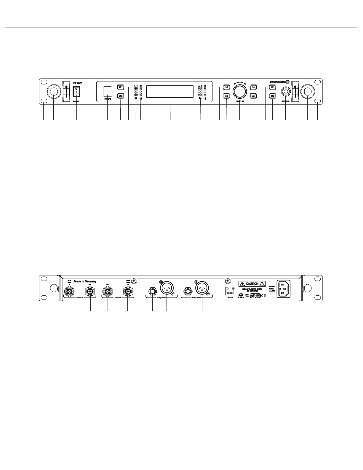
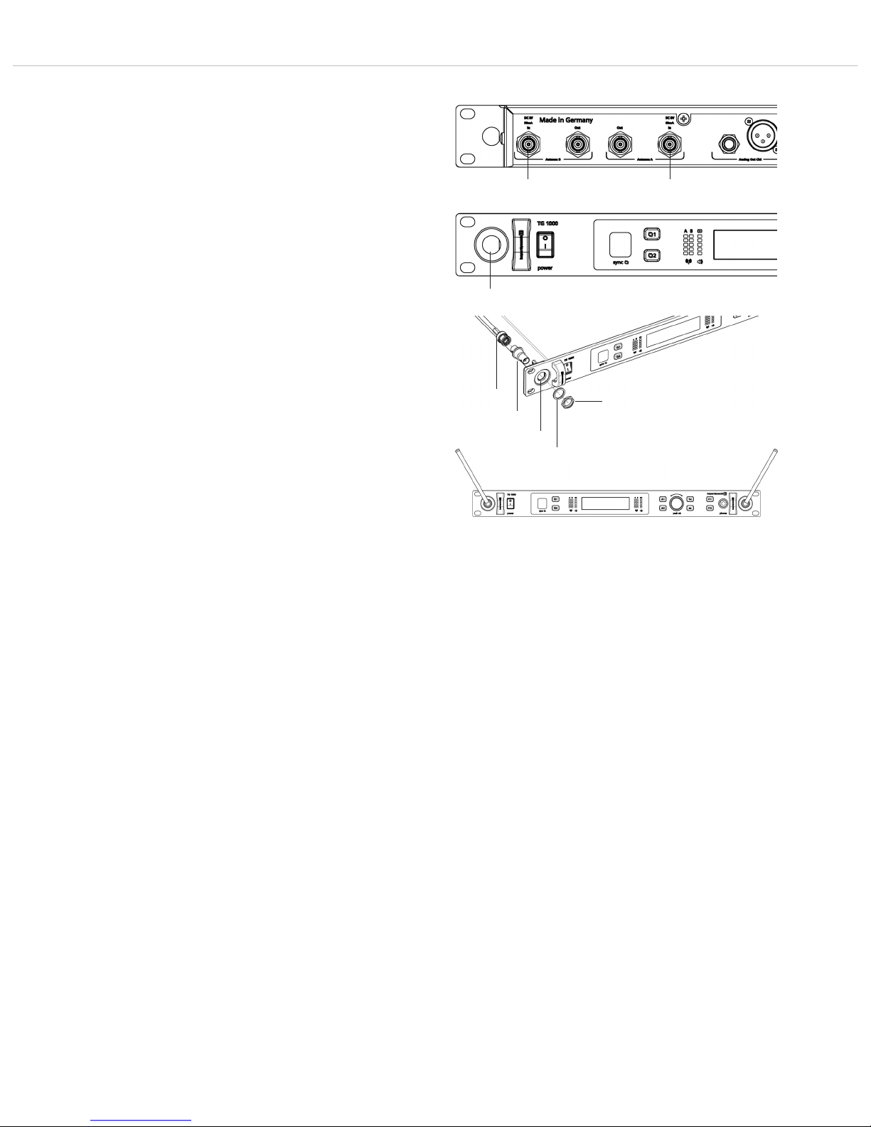
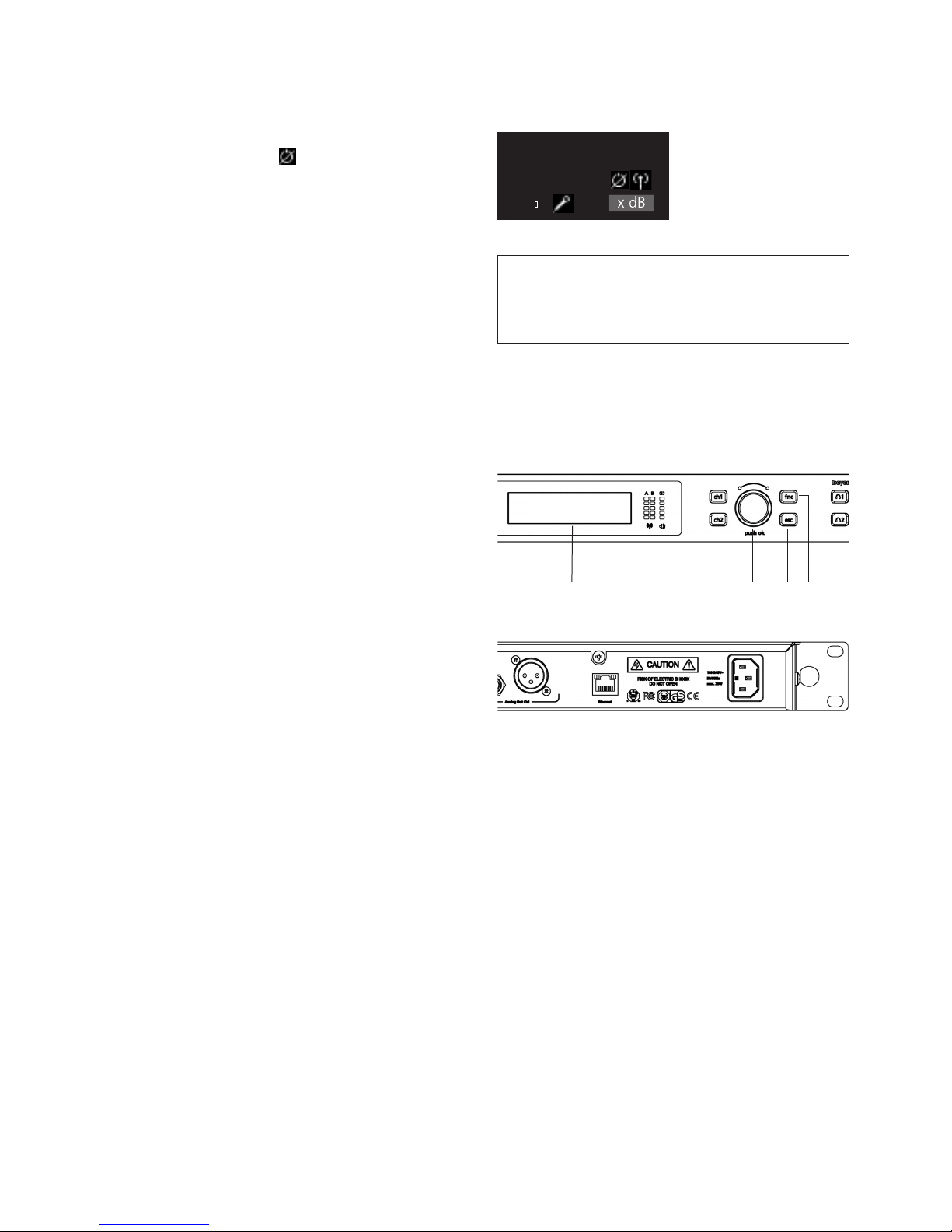
2.1 Controls and Indicators
Hole for 19" rack mounting
Hole for mounting the antennae on the front
On-off switch
Infrared interface for synchronising receiver and transmitter
Button of synchronisation for channel 1 or channel 2
RF indicators channel 1 or channel 2
AF indicators with peak indicator channel 1 or channel 2
Display channel 1 and channel 2
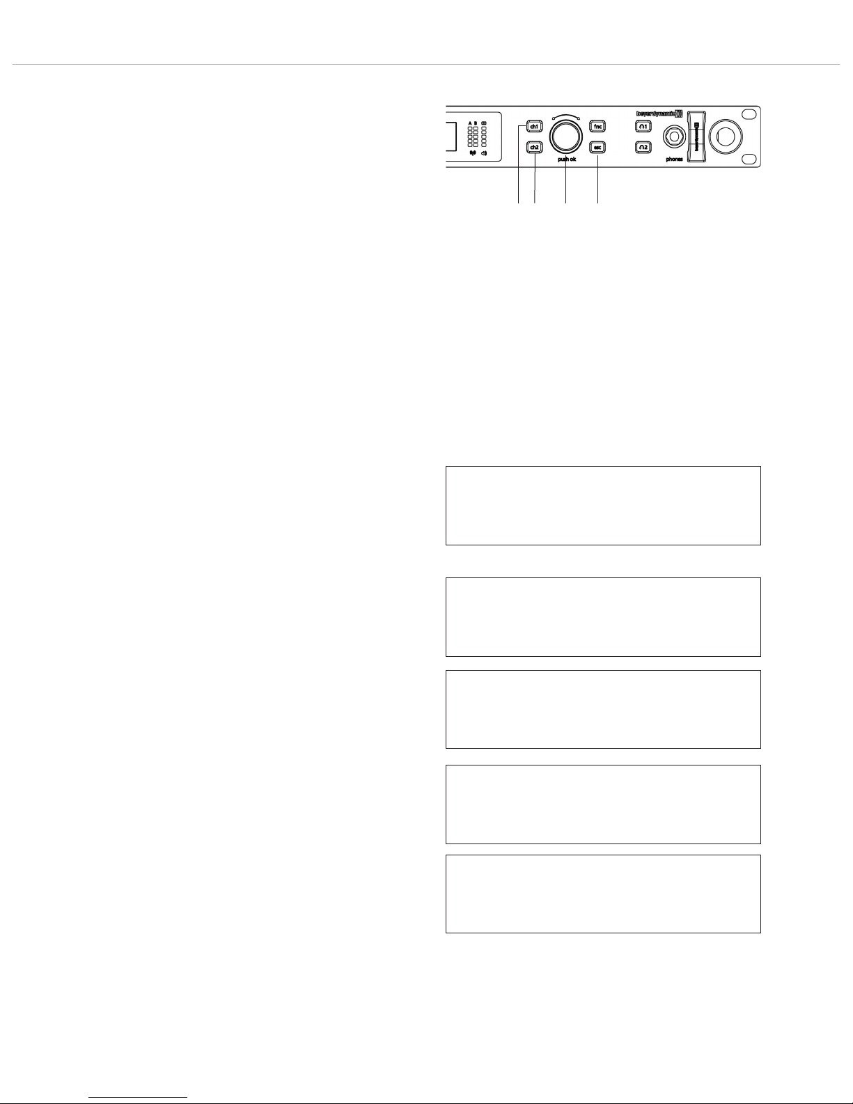
Channel selector button 1 or 2
Rotary switch for selection and settings
ESC button (Escape)
Function button
Button to monitor channel 1 or channel 2 via headphones
Headphone connection, 1/4" stereo jack (6.35 mm)
Antenna input A or B, BNC socket
Antenna output A or B, BNC socket
Audio output, balanced, 3 pole jack, channel 1 or channel 2
Audio output, balanced, 3-pin XLR, channel 1 or channel 2
Ethernet interface (RJ45)
Mains connection
Front View
Rear View
Page 7
TG 1000 – Digital Diversity Receiver
7
2.2 How to Connect the Antennae
• Connect the supplied antennae to the A and B antenna inputs
and set them at an angle (approx. 60°) in the shape of a “V”.
Important: For the diversity operation it is absolutely necessary
to connect both antennae! A weighting circuit ensures that an
antenna is selected that supplies the better signal.
• As an alternative, you can mount the antennae on the front of the
receiver. Please use the WA-CKF antenna front mounting kit.
• Connect the antenna cable of the antenna front mounting kit to
the A and B antenna inputs .
• Remove the protective caps from the holes for mounting the
antennae on the front .
• Remove the nuts and washers of the supplied adapters.
• Slide the adapters through the appropriate hole with the thread
of the adapter showing to the front.
• Tighten the adapters with the washers and the nuts.
• If required, mount the receiver into a 19" rack.
• Connect the antenna cables to the rear of the adapter.
• Connect the antennae to the front (BNC sockets) of the adapter.
• Set the antennae at an angle in the shape of a “V”.
2.3 How to Connect and Install
Remote Antennae
If the reception is not good, we recommend using remote antennae.
We recommend the passive WA-ATD directional antenna (optional
available).
1. Connect the receiving antennae to the corresponding antenna
inputs and place the antennae to the right and left of the
receiver in the operating range where the transmitter is to be
used. If necessary change the position of the antennae to
improve diversity reception.
2. The distance between the two receiving antennae should be at
least 1 m.
3. The distance between transmitting and receiving antennae
should be at least 3 m to avoid overloading and interference
between different channels. We therefore recommend installing
the antennae in a high position, especially in multi-channel
systems.
4. If the operating range of the transmitters is greater than the
stage, the antennae can be mounted vertically on the ceiling.
The distance between the two receiving antennae should be
approximately half the total operating range.
Important:
1. Install the receiving antennae in the same area as the transmitter.
2. To avoid interference do not install the antennae near digitally
controlled components.
3. Keep a minimum distance of 0.5 m from metallic objects,
including reinforced concrete walls or pillars.
4. Do not bend the antenna cables at the antenna input, and
ensure that they are not subjected to undue stress.
Antenna
cable
Adapter
Nut
Washer
Page 8
TG 1000 – Digital Diversity Receiver
8
2.4 Mounting and Connection
2.4.1 Where to Place the Receiver
• Place the receiver in the same room where the transmission takes
place.
• Place the receiver as close as possible to the transmitter. For
optimal reception, a free line of sight is advisable between transmitter and receiver.
• Do not place the receiver near digitally controlled devices.
2.4.2 Rack Mounting
• The receiver is provided with holes on the left and right hand
side for 19" rack mounting.
• Insert the receiver into the 19" rack and tighten it with four
screws (not included in the delivery).
Warning!
• When installing the receiver into a 19 "rack or with other devices
into a rack, the ambient temperature, the mechanical stress and
the electrical potentials will be different than for devices that are
available separately.
• If you install more than one receiver into a rack, you should leave
one height unit free or you should make sure that there is an
appropriate ventilation (e.g. through ventilation panels), because
of the heat between the receivers.
• The ambient temperature of the rack must not exceed the
temperature specified in the technical specifications.
• Make sure that the rack is not top-heavy with too many devices
and will overturn.
• When connecting to the power supply read the information on
the typeplate. Avoid overloading circuits. If necessary, provide an
overcurrent protection.
2.4.3 How to Connect the Receiver to a
Microphone Input
• The receiver is provided with balanced audio outputs.
• Connect the balanced XLR or jack output of the appropriate
channel 1 or 2 to the balanced microphone input of the mixing
console or amplifier.
• Adjust the level of the audio output to the input level of the
amplifier or the mixing console in the menu settings of the
appropriate channel. Refer also to chapter 2.6 “Menu Settings”.
2.4.4 How to Connect the Receiver to the Mains/
Disconnect from the Mains
• Verify that the voltage rating of the receiver matches that of the
AC mains outlet you are to use.
Warning: If you connect the receiver to the wrong voltage, you
may seriously damage it.
• Connect the power cable to the mains connection and to a
mains socket.
• To disconnect the receiver from the mains, pull the plug out of the
appliance inlet at the rear side of the device.
Page 9

TG 1000 – Digital Diversity Receiver
9
2.5 Setting up
2.5.1 How to Operate the Receiver
• After having mounted and connected the receiver, turn it on with
the on-off switch .
• Standard Display
The standard display for each of the two channels will be
shown. If a valid transmitter signal is received on the selected
frequency, the display background will be black. If there is no valid
transmitter signal available, the colour of the display background
will turn white. In this case there will be no audio signal.
• By default it is displayed:
1. line: the currently selected name (e.g. name of the artist)
2. line: the currently selected frequency
3. line: the currently selected frequency group and channel
4. line: when valid transmitter signal
is available: Battery status, transmitter type,
microphone capsule and gain in dB
when no valid transmitter signal
is available: No Tx or Enc Err
• All buttons on the front of the receiver are highlighted in white.
When a button is pressed or activated, the highlighted light will
turn red.
• For turning the receiver off, use the on-off switch . The buttons
will no longer be highlighted.
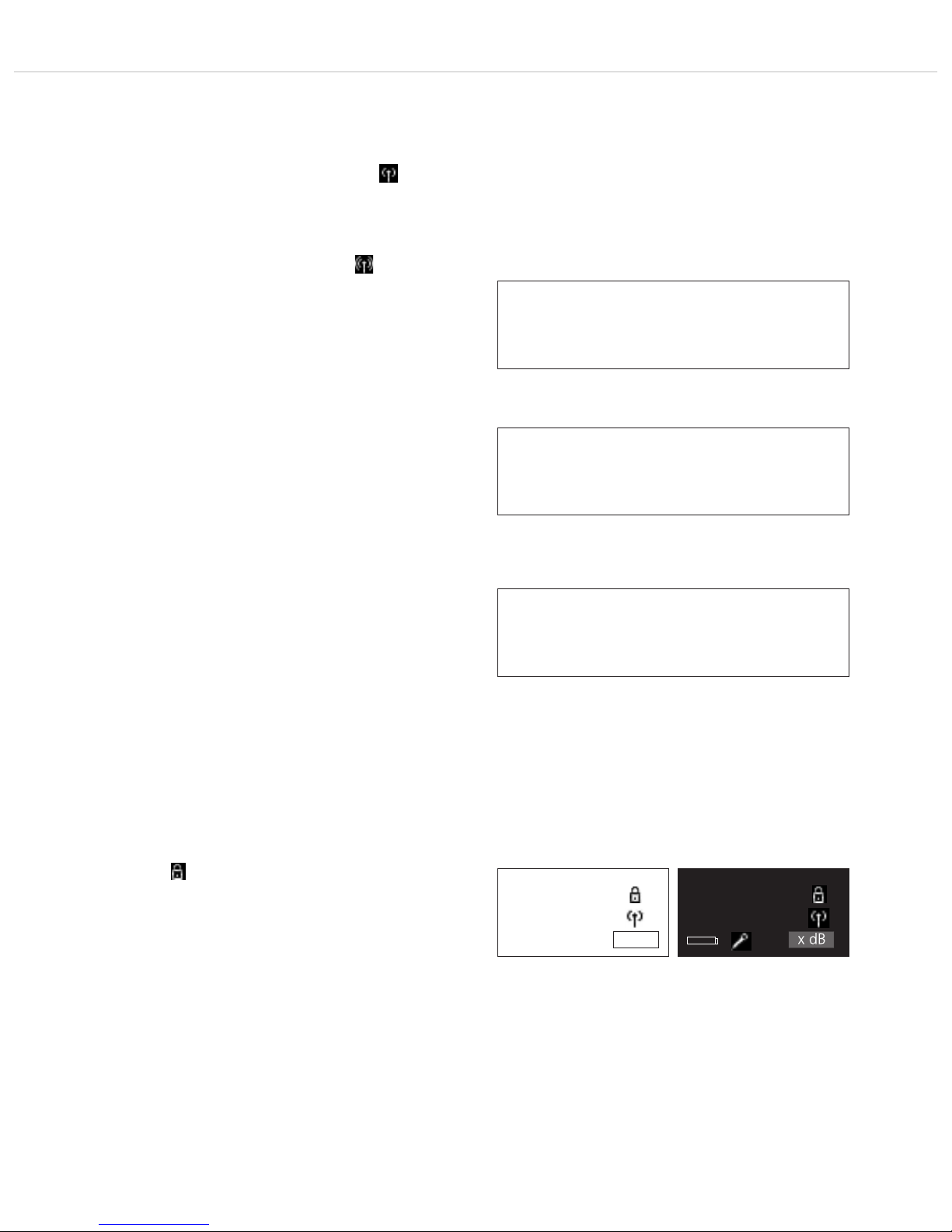
• Possible icons of the standard display and their meaning
A handheld transmitter is used.
A beltpack transmitter is used.
The “Power Lock” function is activated.
The “Encryption” function is activated.
“RF Power” has been set to “Standard”.
“RF Power” has been set to “High”.
Name
xxx.xxxMHz
GR/CH --/-No Tx x dB
Display when there is a valid transmitter signal available
Display when there is no valid transmitter signal available
Name
xxx.xxxMHz
GR/CH --/--
xxx x dB
Name
xxx.xxxMHz
GR/CH --/--
xxx x dB
Name
xxx.xxxMHz
GR/CH --/-Enc Err x dB
Page 10
TG 1000 – Digital Diversity Receiver
10
2.6 Menu Settings
• At the receiver you can adjust settings for name, frequency group,
frequency, digital gain etc. in different menus for channel 1 or 2.
• Select channel 1 or 2 by pressing the appropriate channel selector
button .
• When the channel selector button is highlighted in red and
the display is changing, you can scroll through the menu by
turning the rotary switch and enter the sub-menu by pressing
the rotary switch to make some settings and confirm them
afterwards. When a setting is confirmed by pressing the rotary
switch the “OK” message will be displayed.
• With the ESC button you can cancel the entry within the menu
or sub-menu. The the entries are not accepted and the original
entries will be displayed.
• Caution: If you do not operate the rotary switch for a few
seconds, the appropriate sub-menu will automatically be left and
the default screen will be displayed . Settings, which are not
confirmed by pressing the rotary switch will not be stored.
• On the right hand side of the individual sub-menus the channel
is displayed for which the settings can be done, i.e. “1” or “2”.
• Note: If a setting (except “Digital Gain” and “Analog Out”) is
changed, the appropriate button of synchronisation will
illuminate red.
• The following settings are possible:
• Name
Here you can enter the name of the artist.
Press the rotary switch to enter the sub-menu. Turn the rotary
switch to the left or right to select the letter/character. Press the
rotary switch to confirm.
• Quick Scan
Here you can select a channel or frequency from a predefined
group according to the respective region code (A, B, C, D or E).
Press the rotary switch to enter the sub-menu. Turn the rotary
switch to the left or right to select the requested group. From
the information at the bottom you can see how many channels
the group contains. Press the rotary switch to confirm the
selected group.
Now you can select a channel from the previously selected group
from which to start the scanning. From the information at the
bottom you can see the frequency of the selected channel. Turn
the rotary switch to the left or right to select the requested
channel. Press the rotary switch to confirm the selected channel.
The message “Scanning” will be displayed.
After the scanning the next free channel will automatically be
selected. The selected channel and its frequency are displayed.
As a user you can generate groups (“User Groups”) with
appropriate channels and frequencies by using the “Chameleon”
software, with which you can enter the groups into the receiver.
These groups are marked with a “U”.
• Name: Sample
▼ Quick Scan
1
▲ Name: Sample
• Quick Scan
▼ GR/CH
• Search Group: xx
xx Channels (xxx - xxx MHz)
1
1
• Start Channel: xx
Freq: xxx.xxx MHz
1
Channel xx selected.
Frequency xxx.xxx MHz
1
Page 11

TG 1000 – Digital Diversity Receiver
11
• Frequency Group (GR) / Channel (CH)
Here you can select a channel or frequency from a predefined
frequency group according to the respective region code (A, B,
C, D or E).
Press the rotary switch to enter the sub-menu. Turn the rotary
switch nto the left or right to select the requested group. From
the information at the bottom you can see how many channels
are in the appropriate group. Press the rotary switch to confirm.
Then turn the rotary switch to the left or right to select the
requested channel from the previously selected group. From the
information at the bottom you can see the appropriate frequency.
Press the rotary switch to confirm.
As a user you can generate groups (“User Groups”) with
appropriate channels and frequencies by using the “Chameleon”
software, with which you can enter the groups into the receiver.
These groups are marked with a “U”.
• Frequency
Here you can manually select a frequency between 470 and
789 MHz regardless whether it is in a group or not.
If you select a frequency manually, it is displayed in the default
screen by “GR / CH --/--”.
Press the rotary switch to enter the sub-menu. Turn the rotary
switch to the left or right to select the first three numbers of
the requested frequency. Press the rotary switch to confirm.
• Digital Gain
Here you can digitally adapt the level of the audio output to the
input level of the amplifier or mixing console, i.e. if the signal,
which is picked up with the microphone is very low, it can be
amplified with “Digital Gain”.
Press the rotary switch to enter the sub-menu. Turn the rotary
switch to the left or right to select the amplification in 3 dB
steps between 0 dB and +30 dB. Press the rotary switch to
confirm.
• Analog Out
Here you can analoguously adapt the level of the audio output to
the input level of the amplifier or mixing console. In particular
when there is an instrument directly connected to the beltpack
transmitter, it is recommended to set the amplification via
“Analog Out”.
Press the rotary switch to enter the sub-menu. Turn the rotary
switch to the left or right to select 0 dB or +12 dB. Press the
rotary switch to confirm.
▲ Quick Scan
• GR/CH: xx / xx
▼ Freq: xxx.xxxMHz
▲ GR/CH
• Freq: xxx.xxxMHz
▼ Digital Gain: x dB
▲ Freq: xxx.xxxMHz
• Digital Gain: x dB
▼ Analog Out: x dB
▲ Digital Gain: x dB
• Analog Out: x dB
▼ RF Power: High
1
1
1
1
• GR/CH: xx / xx
xx Channels (xxx - xxx MHz)
1
• GR/CH: xx / xx
Freq: xxx.xxx MHz
1
Page 12
TG 1000 – Digital Diversity Receiver
12
• RF Power
Here you can set the RF power.
The “Standard” setting is recommended when the transmitter is
close to the receiving antennae or with multi-channel systems to
avoid interferences due to intermodulation.
“Standard” is displayed by the following symbol:
The “High” setting is recommended when there are problems
with the range or with a larger distance between transmitter and
receiving antennae.
“High” is displayed by the following symbol:
Press the rotary switch to enter the sub-menu. Turn the rotary
switch to the right or left to adjust the desired RF power to
“High” or “Standard”. Press the rotary switch to confirm.
• Battery
Here you can select, if there is an alkaline battery or NiMH
rechargeable battery inside the transmitter so that the battery
status is displayed correctly.
Press the rotary switch to enter the sub-menu. Turn the rotary
switch to the right or left to select the inserted battery:
“Alkaline” or “NiMH”. Press the rotary switch to confirm.
• Encryption
Here you can activate or deactivate the encryption of audio data.
The encryption is used to avoid unauthorised listening.
Press the rotary switch to enter the sub-menu. Turn the rotary
switch to the right or left to activate (On) or deactivate (Off) the
encryption. Press the rotary switch to confirm.
Important: When you activate the encryption function (On) the
receiver will generate a code. In order to communicate with each
other the receiver and transmitter must have the same code.
Therefore, you must synchronize receiver and transmitter. Refer
also to chapter 2.9 “Synchronisation”.
Caution: Each time when you activate the encryption function
again (On), a new code will be generated which must be
transmitted to the transmitter.
If the transmitter and receiver do not have the same code or if an
uncoded receiver tries to receive an encoded transmitter, the
receiver displays the message “Enc Err” and the background of
the display will turn white.
When the encryption function is activated, a lock symbol will be
displayed:
▲ Analog Out: x dB
• RF Power: High OR Standard
▼ Battery: Alkaline
1
▲ RF Power: High
• Battery: Alkaline OR NiMH
▼ Encryption: On
1
Name
xxx.xxxMHz
GR/CH --/-Enc Err x dB
Name
xxx.xxxMHz
GR/CH --/--
xxx x dB
▲ Battery: Alkaline
• Encryption: On OR Off
▼ Power Lock: On
1
Activated encryption
Code for transmitter / receiver
are not the same
Activated encryption
Code for transmitter / receiver
are the same
Page 13
• Power Lock
Here you can set if the transmitter can be switched off via its
on-off button or not. When the “Power Lock” function is enabled
(On), the transmitter cannot be accidentally turned off and the
following symbol is displayed:
However, the transmitter can be turned off when the “Power
Lock” function is activated: When the transmitter display shows
the message “Power Locked”, release the on-off button and
press the on-off button once again until the “Off” message is
displayed.
Press the rotary switch to enter the menu. Turn the rotary
switch to the right or left to enable (On) or disable (Off) the
“Power Lock” function. Press the rotary switch to confirm.
Important: After having confirmed the selected option, you must
synchronise the transmitter again. Refer also to chapter 2.9
“Synchronisation”.
TG 1000 – Digital Diversity Receiver
13
▲ Encrption: On
• Power Lock: On OR Off
1
2.7 Function Settings
• On the receiver you can adjust settings when the receiver is
operating in a network or you can update the firmware of the
transmitters. Furthermore, you can display information about
support. For the functions described in the chapters 2.7.1 to 2.7.7
the receiver must be turned on and connected to a network via
the Ethernet interface .
• Press the function button (fnc) .
• When the function button is highlighted in red and the
display is changing, turn the rotary switch to scroll through
the menu and press the rotary switch to enter the sub-menu
for settings which you can confirm afterwards. When a setting is
confirmed by pressing the rotary switch , the message “OK” is
displayed.
• With the ESC button you can cancel the entry within the
menu. Then the settings will not be accepted and the original
settings will be reset.
• Caution: When you do not operate the rotary switch for a few
seconds the menu will automatically be left and the default sceen
will be displayed . Settings which are not confirmed by pressing
the rotary switch will not be stored.
• In the individuals menus “f” will be displayed on the right hand
side to indicate function.
Name
xxx.xxxMHz
GR/CH --/--
xxx x dB
Activated “Power Lock” function
Page 14

TG 1000 – Digital Diversity Receiver
14
2.7.1 How to Connect a Receiver to a Network
• When you connect a receiver to a network, use a CAT5 patch
cable to connect the receiver via the Ethernet interface . Turn
on the receiver. For using wireless devices (e.g. tablet PC, iPhone,
iPad etc.) a Wi-Fi network is needed. You can connect the receiver
to a switch or router with DHCP server. Make sure that in the
network, there is only one DHCP server active.
If the router is operated as Access Point in a Wi-Fi network, you
can access the receiver with Wi-Fi devices.
• Adjust the settings for the network on the receiver as described
in the following.
• Press the function button . “Network” is displayed . Press
the rotary switch to enter the “IP” sub-menu.
IP
• In the “IP” sub-menu you can display the IP address assigned to
the receiver and change it if necessary. The IP address consists of
4 bytes. Each byte consists of three numbers (from 0 to 255).
If you want to assign the IP address manually, select the
“Manual” function in the “Mode” sub-menu (refer also to the
“Mode” paragraph). Afterwards select the “IP” sub-menu by
turning the rotary switch to the left and press the rotary switch
to access the sub-menu.
Turn the rotary switch to the right or left to select a value
between 0 and 255. Press the rotary switch to confirm the first
byte and to go to the next byte. Repeat the last two steps to enter
all four bytes. When you have set the IP address, press the rotary
switch to confirm.
• Network
▼ RF-Meter
f
• IP: 0. 0. 0. 0.
▼ Mask: 0. 0. 0. 0.
f
Page 15

TG 1000 – Digital Diversity Receiver
15
Mask
• In the “Mask” sub-menu you can display or change the net mask
assigned to the receiver. The net mask consists of 4 bytes. Each
byte consists of max. three numbers (from 0 to 255). In
conjunction with the IP address of the receiver the net mask
determines which IP addresses the device its searching in its own
net and which it could reach via a router in other networks. It
separates the IP address into a net prefix and component. The net
prefix must be the same with all devices within the net, the
component of each device within the network must be different.
In order to manually assign a net mask, select “Manual” function
in the “Mode” sub-menu (refer also to the “Mode” paragraph).
Turn the rotary switch to the left and select the “IP” sub-menu
and press the rotary switch to enter the sub-menu.
Turn the rotary switch to the right or left to select a value
between 0 and 255. Press the rotary switch to confirm the first
byte and go to the next byte. Repeat the last two steps to enter
all four bytes. When you have set the net mask, press the rotary
switch to confirm.
Mode
• Turn the rotary switch to the right and press the rotary switch
to access the “Mode” sub-menu. By pressing and turning the
rotary switch you can select “DHCP” or “Manual”. To confirm
the selection press the rotary switch .
In a network you can use both switches and routers with DHCP
server. Please note that only one DHCP server in the network is
active due to the allocation of IP addresses.
If you use a router with a DHCP server, select “DHCP”. Then the
automatic integration of the receiver to an existing network
without the manual configuration is possible. When starting the
receiver it can get the IP address, the net mask, the gateway, DNS
server and if necessary WINS server from a DHCP server. With the
automatic assignment a range of IP addresses is defined on the
DHCP server. This area is set in a router with DHCP server. If the
address is out of this range allocated to a DHCP client, then it
belongs to, whichever is defined “Lease time” in the DHCP
server (router), which determines the duration of the assignment
between IP address and MAC address.
If you use a switch or router without an active DHCP server,
select “Manual”. You can set the IP address in the “IP” menu
manually.
▲ Mask: 0. 0. 0. 0.
• Mode: DHCP OR Manual
▼ Device ID: xx
f
▲ IP: 0. 0. 0. 0.
• Mask: 0. 0. 0. 0.
▼ Mode: DHCP
f
Page 16

TG 1000 – Digital Diversity Receiver
16
Device ID
• Turn the rotary switch to the right and press the rotary switch
to access the “Device ID” sub-menu. Here you can select the
Device ID (1 - 99) of the receiver by pressing and turning the
rotary switch . To confirm press the rotary switch .
The Device ID defines the allocation of the devices in the
“Chameleon” software. In the basic view of the software the
devices are displayed one below the other similar to a rack with
ascending Device ID.
Important: Please note that you can change the Device ID only
on the receiver. Make sure that you do not assign the same
Device ID twice.
Mac
• Turn the rotary switch to the right and read the MAC (Media
Access Control) address in the “Mac” sub-menu of the receiver.
The MAC address is stored in the receiver and cannot be changed.
Each receiver has a different MAC address. This ensures that in a
network with a DHCP server each receiver gets a different IP
address.
▲ Device ID: xx
• Mac: 00:04:A3:3C:FE:93
f
▲ Mode: DHCP
• Device ID: xx
▼ Mac: 00:04:A3:3C:FE:93
f
Page 17

TG 1000 – Digital Diversity Receiver
17
2.7.2 Chameleon Software
Each TG 1000 receiver is provided with an integrated web server with
an own web page. In order to configure and monitor your TG 1000
receivers you need not install any software. You only need a
network connection and an network-compatible device (client) with
web browser. Therefore, you can control your TG 1000 system with
a PC, Mac, tablet PC or smartphone.
If you use the Internet Explorer from Microsoft, make sure that it is
version 8 or higher.
For a smooth operation of the Chameleon software your TG 1000
receivers must correctly be connected to a network. Then they can be
operated in the manual or DHCP mode (default). With the manual
mode you must manually assign each connected receiver a different IP
address in the sub menu “Functions -> Network”. With the DHCP
mode the IP address is assigned by the so-called DHCP server, which
is integrated in each standard router. If the DHCP mode is not used,
a usual Ethernet switch will do for networking. In this case the
receivers must be operated in the manual mode. In this network,
without a DHCP server the client device also must receive a static IP
address.
In order to use the Chameleon software with the client device, it
can be linked to any TG 1000 receiver. For this you have to enter the
IP address of the receiver in your web browser (e.g.
“192.168.1.101”). The IP address of the receiver can be found in
the sub menu “Functions -> Network”. You can connect to any
receiver. After a successful transmission of the web page the basic
screen of the Chameleon software is displayed in the browser
window. An overall view of all receivers in a virtual rack is displayed.
The sequence of the displayed receivers is determined by the device
ID, which can be selected in the sub menu “Functions -> Network”
of the receiver. In order to ensure a clear assignment, you must
assign each receiver a different device ID. The receivers are displayed
in an ascending order.
Frequency Scan
• The frequency selection in a particular frequency range can be
made via the frequency scan. In this way you can also find out if
there are interferences or not with individual frequencies.
• Select the “Frequency Scan” button.
• Select the resolution of the scan by selecting the measurement
distances of 100 kHz, 200 kHz or 500 kHz.
• Enter the start frequency and stop frequency of the range within
which it is to be scanned.
• Select the channel for which the scan is to be made. Due to the
scanning process the selected channel is occupied while the other
channel can still receive audio signals. Before the channel
designation CH 1 or CH 2 you will find the appropriate Device ID.
• Select the “Start” button.
• A scanning message will be displayed.
Page 18

TG 1000 – Digital Diversity Receiver
18
Frequency Scan
• The scan displays the RF signals of the selected frequency range.
These signals can be microphone signals or interferences caused
by DVB-T channels.
Clear Log
• Select the “Clear Log” button to clear messages in the display.
Move to Bottom / Top
• Select the “Move to Bottom” or “Move to Top” button to change
the position of the display.
Walking Test
• The “Walking Test” function is used to find out, using a portable
device, where there are problems with the reception on a stage.
Furthermore, it also possible to recognise problems with the
antennas.
• Select the “Walking Test” button.
• Select the channel under “Select Device”.
• Select the “Start” button. Both antenna signals are displayed over
the time. Places where dead spots occur are indicated by a lower
signal strength.
• The strip in the middle is the so-called diversity information which
indicates the currently active antenna.
Receiver Settings
• With the “Chameleon” software you can change the receiver
settings. The changes are applied directly in the device. Furthermore, all status messages are also displayed on the receiver itself.
The Sync LED lights up red when the transmitter and receiver have
to be synchronised again.
Page 19

TG 1000 – Digital Diversity Receiver
19
• Select the channel window of the receiver to enter the channel
menu.
• You can enter the following settings:
Name: You can enter the artist’s name.
RF Power: You can set the transmitter power.
Battery: You can select if an alkaline or rechargeable NiMH
battery has been inserted in the transmitter.
Encryp: You can enable or disable the encryption.
Power Lock: You can enable or disable the Power Lock function
of the transmitter.
Freq MHz: You can enter a frequency manually.
Group / Channel: You can select a channel within the selected
group stored in the receiver.
Di.Gain: You can set the “Digital Gain”. Refer also to chapter 2.6
“Menu Settings”.
Boost: You can set the “Analog Out” boost. Refer also to
chapter 2.6 “Menu Settings”.
• You will find detailed descriptions of each setting in chapter 2.6
“Menu Settings”.
• Select the “Back to Front” button to return to the front view of
the receiver.
Device-specific View
• If you click on the Device ID of the receiver, you will receive more
information such as IP address, Device ID, firmware of receiver
controller and DSP, transmitter firmware (when transmitter is
active).
• On the right hand side there is a selection dialogue to load user
groups into the receiver.
• Select a file to select the “User Group”.
• Select the “Submit” button to send the selected user group to
the receiver.
Restricted Access
• For safety reasons there is a restricted access, so that only one
client can be connected to the software.
• If another client tries to connect to the software, an error message
will be displayed.
Page 20

TG 1000 – Digital Diversity Receiver
20
2.7.3 How to Display the RF Level
• Select the function button to display the RF level for both
channels when transmitters are switched on. Turn the rotary
switch to select the “RF-Meter” sub-menu. Press the rotary
switch to enter the sub-menu.
• The RF level of both channels is displayed by bars.
▲ Network
• RF-Meter
▼ Quick System Setup
f
2.7.4 How to Select a Frequency for all Receivers
in a Network
• The “Quick System Setup” function is used to select frequencies
for all channels in a network. Press the function button of any
receiver. Turn the rotary switch to select the “Quick System
Setup” sub-menu. Press the rotary switch to enter the submenu.
Press the rotary switch to enter the sub-menu. Turn the rotary
switch to the left or right to select the requested group from
which to start the scanning. The information at the bottom shows
how many channels are in the group. Press the rotary switch
to confirm the selected group.
From the previously selected group you can now select a channel
from which to start the scanning. From the information at the
bottom you can see the frequency of the selected channel. Turn
the rotary switch to the left or right to select the requested
channel. Press the rotary switch to confirm the selected
channel. The message “Scanning” will be displayed. The scan will
automatically be finished when enough channels have been
found for all receivers in the network. If there are not enough
channels available, an appropriate message will be displayed.
The message “Frequency setting sent” will be displayed when the
frequencies have been sent to all receivers in the network.
After the scanning, the existing receivers in the network will
display an information to select (Yes) or reject (No) the found
frequency for the receiver. Turn the rotary switch to the left or
right to select “Yes” or “No”. Press the rotary switch to
confirm your selection.
No = the existing frequencies for the channels will be maintained
Yes = the existing frequencies for the channels will be overwritten
The receiver from which the “Quick System Setup” function was
started, will accept the found frequency in any case.
Important: After performing the “Quick System Setup” function,
you must synchronise the transmitter/s again. Refer also to
chapter 2.9 “Synchronisation”.
▲ RF-Meter
• Quick System Setup
▼ Factory Reset
f
Quick System Setup
• Search Group: xx
xx Channels (xxx - xxx MHz)
f
Quick System Setup
• Start Channel: xx
Freq: xxx.xxx MHz
f
Quick System Setup
• Set Frequency: No OR Yes
Don’t assign new frequency OR Assign new frequency
-80 -70 -60 -50 -40 -30 dBm
A
B
1
A
B
2
Page 21

TG 1000 – Digital Diversity Receiver
21
2.7.5 Factory Reset
• For a factory reset press the function button . Select the
“Factory Reset” sub-menu by turning the rotary switch . Press
the rotary switch to access the sub-menu.
• Turn the rotary switch to select, if you want to reset the factory
or standard settings or not. Press the rotary switch to confirm.
▲ Quick System Setup
• Factory Reset
▼ Help
f
• Restore Defaults: Yes OR No
f
2.7.6 How to Display Support Information
• To display the support information press the function button .
Select the “Help” sub-menu by turning the rotary switch . Press
the rotary switch to access the sub-menu.
• You can read general support information such as country-specific
contacts for technical service or the web address of the TG 1000
helpcentre.
• If you have a smartphone you can scan the QR code on the right
hand side to receive further information.
▲ Factory Reset
• Help
▼ Version Info
f
SUPPORT
and software updates
www.beyerdynamic.com/
tg1000/help
2.7.7 How to Display the Version
• In order to display the version press the function button . Select
the “Version Info” sub-menu by turning the rotary switch .
Press the rotary switch to access the sub-menu.
• Here you can read the current firmware version of the receiver
and the used transmitters.
Important: The transmitters must be switched on.
▲ Help
• Version Info
▼ Tx Upgrader
f
MCU: Rev-00.2.38
DSP 0.25
Tx: Ch.1: 0.10
Tx: Ch.2: 0.0
Page 22

TG 1000 – Digital Diversity Receiver
22
2.7.9 How to Update the Transmitters
• In order to update the firmware of the transmitter, please
proceed as described in the following.
• Press the function button . Select the “Tx Upgrader” sub-menu
by turning the rotary switch . Press the rotary switch to
access the sub-menu.
• Press the rotary switch to start the upgrade.
Follow the instructions on the display and press the rotary
switch each time to confirm.
▲ Version Info
• Tx Upgrader
▼ Region Code: A
f
TG 1000 Bootloader
For Upgrade connect to ...
IP-Adresse: 0. 0. 0. 0.
MAC: 00:04:A3:3C:DB:A4 00.01.5
Tx Upgrader
Push Enc to start!
f
2.7.8 How to Update the Firmware of the Receiver
• You can update the firmware of the receiver with the so-called
“Bootloader” via the network.
• You will find the appropriate update of the firmware (for receiver
and transmitters) and the Chameleon software on the internet
at: www.beyerdynamic.com/tg1000/help
• Download this update file on your PC.
• Connect the receiver via the Ethernet interface to a PC by using
a CAT5 patch cable.
• In order to start the Bootloader mode, press the rotary switch
while turning the receiver on.
• When you press the function button , you can check or adapt
the network settings. Refer also to chapter 2.7.1 “How to
Connect a Receiver to a Network”.
• Enter the IP address, which is displayed on the receiver, into an
internet browser.
• In the internet browser a page will be opened where you can load
the new firmware as file into the receiver.
• Select the “Select file” button and select the file from the opened
window.
• Select the “Submit” button to confirm.
• The receiver displays the transmission status.
• When the message “Upgrade successful” is displayed on the PC,
the transmission to the receiver is finished.
• Turn the receiver off and on again to start the firmware upgrade.
The message “Rx Firmware Upgrading” is displayed .
• The upgrade is ready, when the default screen is displayed .
2.7.10 How to Display the Region Code
• To display the region code press the function button . Select
the “Region Code: A” sub-menu by turning the rotary switch .
• With the Region Code you can recognise which predefined
frequency ranges are provided for which regions in the TG 1000
system:
– Region Code: A 470 - 789 MHz
– Region Code: B 470 - 698 MHz
(without 608 - 614 MHz / US TV channel 37)
– Region Code: C 520 - 694 MHz
– Region Code: D 470 - 628 MHz & 710 - 716 MHz
– Region Code: E 470 - 714 MHz
Note: The Region Code is subject to changes!
▲ Tx Upgrader
• Region Code: A
f
Page 23

TG 1000 – Digital Diversity Receiver
23
2.8 Monitoring
• For monitoring purposes you can listen to channel 1 or 2 with a
headphone.
• Connect a headphone to the headphone connection of the
receiver.
• Press the appropriate button to monitor channel 1 or 2. When
the function is activated, the appropriate button is highlighted
red.
• In the headphone menu you can adjust the volume in 3 dB steps
between -33 and +36 dB with the rotary switch .
Warning: Do not set the volume too high, you can damage
your hearing permanently.
• You can read the volume on the display .
• After a while the display returns to the default screen. The
monitoring function or headphone output is still active.
• To stop the monitoring function, press the appropriate button
again. The headphone menu to adjust the volume is displayed.
Press the appropriate button once again. The display shows the
“OFF” message. The monitoring function or the headphone
output is turned off.
Warning:
We would like to point out that long listening at high volumes can
damage your hearing. A hearing damage always represents an
irreversible impairment. Therefore, please reduce the volume before
use.
Always make sure that the volume is not to high. Rule of thumb: the
higher the volume, the shorter the listening time. According to the
professional association regulations on safety and health at work
(BGV B3) in Germany, noise pollution at workplace must not exceed
85 dB (low volume). This corresponds to an allowed maximum
listening time of 8 hours. If the volume is increased by 3 dB, the
allowed listening time is halved, i.e. at 88 dB the duration is 4 hours,
at 91 dB 2 hours etc.
1
+12dB
Page 24

TG 1000 – Digital Diversity Receiver
24
2.9 Synchronisation
• Via an infrared interface the receiver can transmit frequency and
other settings such as encryption and “Power Lock” of the
appropriate channel to a transmitter.
• In order to transmit the settings to a transmitter, press the button
for synchronisation for channel 1 or 2 on the receiver.
• Inside the battery compartment of the transmitter there is an
infrared interface.
• When the pressed button for synchronisation is highlighted
red, hold the infrared interface of the handheld transmitter or
the beltpack transmitter in the open battery compartment
of the switched on transmitter directly in front of the infrared
interface of the receiver.
• When the message “SYNC successful” is displayed, the process
is completed. Frequency and other settings have been successfully transmitted to the transmitter.
How to Synchronise Two Transmitters on the Same Channel
• Press the on-off button of the handheld or beltpack transmitter
for approx. 8 seconds to enter the “RF off” mode. Now you can
synchronise a spare transmitter on the same channel, although
the main transmitter is still activated (audio will still work when
synchronising).
• Synchronise the spare transmitter as described above.
• In order to leave the “RF off” mode switch the transmitter off
and on again.
Important: Before you switch the spare transmitter off and on
again, you must turn off the main transmitter, because otherwise
the channel can be interfered when two transmitters are
simultaneously active on the same frequency.
Beltpack transmitter
2.10 Multi-Channel Operation
(Cascading Several TG 1000 Receivers)
• The receiver is provided with an integrated active antenna splitter.
• For a multi-channel operation with two antennae you can
connect 12 receivers (24 channels) at maximum.
• Connect the antennae to the antenna inputs of the first receiver.
• Connect the antenna inputs of the second receiver to the
antenna outputs of the first receiver and the antenna inputs
of the third receiver to the antenna outputs of the second
receiver etc.
• Use the WA-CKL connecting cables (optionally available).
• Please turn on all receivers, so that they can be supplied with the
antenna signal.
• For large multi-channel systems we recommend using one or
more WA-AS 6 antenna splitters.
Handheld transmitter
Page 25

TG 1000 – Antenna Splitter
25
2.11 WA-AS 6 Antenna Splitter
2.11.1 Controls and Indicators
Front View
Rear View
Hole for 19" rack mounting
Antenna input for front mounting of the antennae, BNC
Status LED to indicate DC voltage supply
Power on LED
Connection for DC powering
Antenna input A or B, BNC
Antenna output A or B, BNC
On-off button for DC voltage supply of antenna amplifiers
2.11.2 General Information
• The WA-AS 6 antenna splitter is a 6-way wideband antenna splitter operating in the frequency range of 470 to 790 MHz.
• With one WA-AS 6 antenna splitter you can operate up to 72 TG 1000 diversity receivers (cascaded) with only two antennae.
• For the diversity operation the WA-AS 6 is provided with two antenna inputs that are distributed to six outputs. The operation is possible with
antennae that are directly or remotely connected.
• Both antenna inputs provide a supply voltage for active antennae or antenna amplifiers.
• An status LED displays the active connection to the antenna amplifier.
Page 26

TG 1000 – Antenna Splitter
26
2.11.3 Mounting and Installation
• For the installation into a 19" rack the WA-AS 6 antenna splitter is provided with 19" holes on the left and right hand side.
• Connect the WA-ATD directional antenna or the WA-ATO omnidirectional antenna to the antenna inputs A and B .
• The antenna outputs of the antenna splitter are connected to the antenna inputs of the receivers by using BNC patch cables (WA-CKL). In order
to ensure the diversity operation, each receiver must be supplied with an A and B antenna signal!
• Connect the supplied power supply unit to an appropriate power outlet and the DC connection . The antenna splitter has not separate
on-off switch and is ready for operation when connected to the mains. The power on LED will illuminate.
• When using WA-AMP antenna amplifiers use the on-off button on the rear of the antenna splitter. The status LED will illuminate.
Caution: When the on-off button is pressed, the DC supply is turned off.
Important notes
• The antenna connections have a DC voltage of 8V DC. In order to avoid a short circuit, they should not touch the housing of the rack.
• Use the WA-AC antenna cable from beyerdynamic. The longer the cable, the higher the attenuation of the high frequency signal.
• For the connection of remote antennae use the WA-AC antenna cable from beyerdynamic. The longer the cable, the higher the RF signal loss.
• The connected antennae and the antenna splitter must have the same frequency range of 470 – 790 MHz.
• By cascading several TG 1000 diversity receivers you can create larger multi-channel systems by using the antenna splitter.
First receiver
Second receiver
Third receiver
Fourth receiver
Fifth receiver
Sixth receiver
Connection of WA-ATD
directional antenna
or
WA-ATO omnidirectional antenna
Connection of WA-ATD
directional antenna
or
WA-ATO omnidirectional antenna
Page 27

TG 1000 – Digital Handheld Transmitter
27
3. Digital TG 1000 UHF Handheld Transmitter
3.1 Controls and Indicators
Thread to attach a microphone head
Cover for battery compartment
Antenna
Infrared interface für synchronisation
Battery compartment
OLED display
On-off button
Page 28

TG 1000 – Digital Handheld Transmitter
28
3.2 How to Attach the Microphone Head
For the TG 1000 handheld transmitter there are different condenser and dynamic microphone capsules available. Refer also to “Optional
Accessories”.
• Put the requested microphone head onto the thread of the handheld transmitter and tighten it clockwise.
• If you want to change the microphone head, unscrew it from the transmitter by turning it anti-clockwise.
• Make sure that you switch off the handheld transmitter before changing the microphone head.
TG V50w
Dynamic microphone head, cardioid polar pattern, for vocals.
Very wide pick-up area. High gain before feedback.
TG V56w
Condenser microphone head, cardioid polar patter, for solo
singers, conference and speeches. Discreet treble boost. High gain
before feedback.
TG V70w
Dynamic microphone head, hypercardioid polar pattern, for
vocals. Powerful sound. Extremely high gain before feedback.
TG V90w
Dynamic ribbon microphone head, cardioid polar pattern, for
vocals. Clear, natural sound. High gain before feedback.
TG V96w
Condenser microphone head, cardioid polar pattern, for vocals.
Uncoloured reproduction. Discreet treble boost for an open and
unobtrusive sound. High gain before feedback.
Page 29

TG 1000 – Digital Handheld Transmitter
29
3.3 How to Insert the Batteries
• Unscrew the cover of the battery compartment anti-clockwise.
• Slide the cover of the battery compartment downwards.
• Insert two alkaline batteries, AA 1.5 V or rechargeable NiMH batteries according to the symbols in the battery compartment .
• Slide the cover of the battery compartment upwards again and tighten it clockwise.
• The current battery status is shown in the display of the transmitter and receiver . Make sure that before the synchronisation the appropriate battery type has been selected in the channel menu.
• When the batteries are low, an empty flashing battery symbol will be displayed . In this case, you should replace the batteries as soon as
possible with new ones.
3.4 How to Operate the Handheld Transmitter
• Turn on the handheld transmitter by holding the on-off button
pressed, until the standard display is shown in the display .
• The display shows the battery status and the name, which has
been entered in the first line of the receiver.
• In the second line, depending on the setting, you will see the
channel and frequency group or the frequency. By pressing the
on-off button briefly several times you can display further
information in the second line.
Further information are: RF power, battery, microphone head and
status of encryption and power lock.
• When you hold the on-off button pressed while turning on,
you can display the region code and version number.
• Make sure that transmitter and receiver operate on the same
frequency.
• The handheld transmitter features a high dynamic range. This is
the reason why it does not have a switch to set the level. With low
signals the audio level can be increased by increasing the “Digital Gain” on the receiver. Refer also to chapter 2.6 “Menu Settings”, “Digital Gain”.
• To turn off the transmitter hold the on-off button pressed until
the message “Off” is displayed.
• If the “Power Lock” function is activated you can nevertheless
turn off the handheld transmitter. Press the on-off button until
the “Power Locked” message is displayed . Release the button
and press the button unit the “Off” message will be displayed.
Then the handheld transmitter is turned off.
Page 30

TG 1000 – Digital Handheld Transmitter
30
3.6 Maintenance
• Protect the handheld transmitter from humidity, knocks and
shock. Avoid dropping the transmitter at all times.
• For cleaning metal surfaces, use a soft cloth moistened with
methylated spirits or alcohol.
• As soon as your microphone sounds dull, you should clean the
integrated pop shield. Proceed as described in the following.
– Unscrew the microphone grille anti-clockwise.
– Pull out the foam pop shield, if necessary use tweezers and
clean it under clear running water.
– If necessary, use a mild washing-up liquid.
– Dry it afterwards with a hairdryer or allow it to dry overnight.
– Clean the microphone grille both inside and out with a slightly
moistened cloth or a soft brush under clear running water
and allow it to dry overnight.
– The microphone grille cannot be cleaned in a dishwasher.
– Place the dry pop shield inside the microphone grille and
replace the microphone grille by screwing it on clockwise.
– With the TG V90w loosen the screws with a small screw-
driver and turn the upper part of the microphone head
anti-clockwise to unscrew it.
– Clean the upper grille under clear running water.
– Allow the upper grille to dry overnight before you replace it.
– The upper grille cannot be cleaned in a dishwasher.
–TheTG V96w is provided with a mesh pop shield.
– For cleaning turn the microphone grille anti-clockwise to
unscrew.
– Turn the wire mesh pop shield anti-clockwise to unscrew.
– Clean the pop shield under clear running water.
– Allow the pop shield to dry overnight before you replace it.
– The wire mesh pop shield cannot be cleaned in a dishwasher.
– Clean the microphone grille inside and outside with a slightly
moistened cloth or a soft brush under clear running water and
allow it to dry overnight.
– The microphone grille cannot be cleaned in a dishwasher.
3.5 Synchronisation / How to Transmit the
Receiving Frequency to the Transmitter
• In order to transmit the frequency and other settings to the
transmitter, press the button for synchronisation on the receiver
for channel 1 or channel 2.
• In the battery compartment of the transmitter there is an infrared
interface.
• During the synchronisation hold the infrared interface in the
open battery compartment of the turned on transmitter directly
in front of the infrared interface on the receiver.
• When the message “SYNC successful” is displayed, the process
is finished.
TG V90w
TG V96w
Page 31

TG 1000 – Digital Beltpack Transmitter
31
4. Digital TG 1000 UHF Beltpack Transmitter
4.1 Controls and Indicators
4-pin mini XLR connector (male) to connect microphones or instruments
AF peak LED
On-off button
Power on LED
Antenna connector, SMA socket
OLED display
Cover of battery compartment
Gain switch 0 dB / -12 dB
Battery compartment
Infrared interface
! Belt clip
!
Page 32

TG 1000 – Digital Beltpack Transmitter
32
4.2 How to Insert the Batteries
• Take hold of the cover of the battery compartment on top at the inlets at the right and left hand side.
• Flap the cover of the battery compartment downwards.
• Insert two alkaline batteries, AA 1.5 V or rechargeable NiMH batteries according to the symbols in the battery compartment .
• Flap the cover of the battery compartment upwards to close. Magnets ensure a secure fastening.
• The current battery status is shown in the display of the transmitter and receiver . Make sure that before the synchronisation the
appropriate battery type has been selected in the channel menu.
4.3 How to Operate the Beltpack Transmitter
• Connect a microphone or the WA-CGI intrument cable to the 4-pin
mini XLR connector .
• Connect the supplied antenna with SMA connector to the antenna
connector .
• Turn on the beltpack transmitter by holding the on-off button
pressed, until the standard display is shown in the display . The
Power on LED will illuminate green.
• The display shows the battery status and the name, which has
been entered in the first line of the receiver.
• On the second line, depending on the setting, you will see the
channel and frequency group or the frequency. By pressing the
on-off button briefly several times you can display further
information on the second line.
Further information are: RF power, battery, microphone head and
status of encryption and power lock.
• When you hold the on-off button pressed while turning on,
you can display the region code and version number.
• Make sure that transmitter and receiver operate on the same
frequency.
• To turn off the transmitter hold the on-off button pressed until
the message “Off” is displayed.
• If the “Power Lock” function is activated you can nevertheless
turn off the handheld transmitter. Press the on-off button until
the “Power Locked” message is displayed . Release the button
and press the button unit the “Off” message will be displayed.
Then the handheld transmitter is turned off.
Page 33

TG 1000 – Digital Beltpack Transmitter
33
4.4 Synchronisation / How to Transmit the
Receiving Frequency to the Transmitter
• In order to transmit the frequency and other settings to the
transmitter, press the button for synchronisation on the receiver
for channel 1 or channel 2.
• In the battery compartment of the transmitter there is an infrared
interface .
• During the synchronisation hold the infrared interface in the
open battery compartment of the turned on transmitter directly
in front of the infrared interface on the receiver.
• When the message “SYNC successful” is displayed, the process
is finished.
4.6 How to Mount the Belt Clip
• The beltpack transmitter is supplied with two belt clip to attach
the transmitter to clothes, belts, a guitar strap etc.
• You can remove the belt clip by pulling it from the fixation of the
beltpack transmitter.
• The belt clips can be mounted vertically or horizontally.
Vertical: to attach the transmitter to clothes or a belt
Horizontal: to attach the transmitter to a guitar strap
! !
4.5 How to Use the Gain Switch
• The beltpack transmitter has a switchable pre-attenuation of
-12 dB, so that sources with an extremely high signal level can be
connected by using the instrument cable (e.g. electric guitars or
basses with active pick-ups). In this case set the gain switch
to -12 dB.
In order to output these signals with an equivalent level at the
receiver, we recommend to set the channel parameter “Analog
Out” to +12 dB in the menu of the receiver. See also chapter 2.6
“Settings menu” the “Analog Out” paragraph.
• If you connect an electret microphone to the microphone input of
the transmitter, you must set the gain switch to 0 dB. If distortions occur at very loud signals, you need a microphone with
a low sensitivity, because the distortions already arise inside the
microphone.
• With quiet signals, the audio level can be increased by increasing
the “Digital Gain” on the receiver. See also chapter 2.6 “Settings
menu” the “Digital Gain” paragraph.
Page 34

TG 1000 – General Instructions for Transmitters
34
5. General Instructions for all Transmitters
• Check the transmitter battery and replace or recharge it if necessary. Use fresh alkaline batteries only or recharge the rechargeable batteries.
• Switch off the transmitter before changing the batteries.
• If the transmitter is not being used for weeks or months, please remove the batteries. Batteries can leak when not being used for a long
time and corrode the conductor strips and components. Repair is not then possible. In this case all warranty claims are null and void. The
description “leak proof” on batteries is no guarantee that they will not run out.
• From time to time the battery contacts should be cleaned with a soft cloth moistened with spirits or alcohol.
• Do not throw used batteries into the domestic rubbish, but hand them in to local collection points.
• For charging rechargeable batteries use standard battery chargers.
6. Comments on the Audio Level
In the development of TG 1000 it was the objective to create a system that transmits audio as accurately as possible, that has a clear level
and is as simple as possible to handle.
In order to cover all relevant practical applications with a wide dynamic range, there are several ways to adjust the audio levels.
Level settings on the transmitter
The TG 1000 system does without the possibility of setting the level on the transmitters, except the sensitivity switch on the beltpack transmitter.
In return, the analogue-digital conversion, and the CODEC used with a very high dynamic range are performed. If required or desired, this
concept makes it possible to comfortably adjust the volume on the receiver without having to synchronise the transmitter or to make new
settings.
Gain switch of the beltpack transmitter:
This switch allows setting a passive attenuation of -12dB. This is required if sources with an extremely high signal level (e.g. electric guitars or
basses with active pick-ups) are to be connected.
For electret microphones the setting of 0 dB must be used. Should distortions still occur at very loud signals, the use of microphones with a lower
sensitivity is required, as in this case, the distortion arises in the microphone itself. The output level of the electret microphone can not be
higher than the supply voltage, which is provided by the beltpack transmitter, and this level can smoothly be processed even in the 0 dB
position. The -12dB attenuation would indeed reduce the level, but not prevent the distortion.
Level settings on the receiver
The receiver provides two possibilities to influence the output level:
1. Digital Gain:
With this parameter, the level can be enhanced digitally. The gain is adjustable from 0dB to +30 dB (in 3 dB steps). A limiter ensures that the
adjusted gain is temporarily reduced at unexpectedly high input levels, and thus overloading of the digital-analogue converter and associated
audible distortion can be prevented.
The use of digital gain is recommended for low input signals. Alternatively the gain to use digital gain can be made also in a mixing console,
since the digital-analogue conversion is also carried out with a very high dynamic range.
2. Analog Out:
With this parameter the gain of the output stage can analogously be influenced. There are two settings available: 0dB and +12 dB. When
needed, the output level can be increased by 12 dB without losses in the dynamic range. The setting of +12 dB is recommended if the
following device needs very high input levels (e.g. line inputs with mixers) or if level losses are to be compensated by the use of-12dB attenuation
at the beltpack transmitter.
Amplification by the entire system
The gain through the entire system can very easily be calculated by adding up the values of all three possible adjustments (gain switch, Digital
Gain and Analog Out) .
If all three values are set to 0dB, the output level is equal to the input level. For example, when using a beltpack transmitter in conjunction with
an instrument cable, TG 1000 behaves as if using a “wireless cable”, because distorted guitar sounds are the same as when using a “real” cable.
When using a handheld transmitter, the output level corresponds to the one of a wired microphone equivalent (except the interchangeable V90w
ribbon microphone head; here, a certain gain is already made in the microphone head itself in favour of an improved signal to noise ratio).
With very loud instruments, which require the -12 dB attenuation on the beltpack transmitter, it is possible to adapt the output level to the input
level by setting the parameter “Analog Out” to +12 dB. In this way, the idea of the “wireless cable” is restored.
Page 35

TG 1000 – Block Diagrams
35
Block Diagrams
Audio Level of Beltpack Transmitter
Audio Level of Handheld Transmitter
Audio Level of Receiver
Page 36

TG 1000 – Components
36
7. Components
Digital UHF Diversity Receiver
Region A Two-channel true diversity receiver, 470 - 789 MHz . . . . . . . . . . . . . . . . . . . . . . . . . . . . . . . . . . . . . . . . . . . Order # 711.357
Region B Two-channel true diversity receiver, 470 - 698 MHz (without 608 - 614 MHz (US TV channel 37) . . . . . . . . . Order # 711.365
Region C Two-channel true diversity receiver, 520 - 694 MHz . . . . . . . . . . . . . . . . . . . . . . . . . . . . . . . . . . . . . . . . . . . Order # 711.373
Region D Two-channel true diversity receiver, 470 - 628 MHz & 710 - 716 MHz . . . . . . . . . . . . . . . . . . . . . . . . . . . . . Order # 711.381
Region E Two-channel true diversity receiver, 470 - 714 MHz . . . . . . . . . . . . . . . . . . . . . . . . . . . . . . . . . . . . . . . . . . . Order # 711.748
Digital UHF Handheld Transmitter
Region A Handheld transmitter for TG 1000 receiver, 470 - 789 MHz . . . . . . . . . . . . . . . . . . . . . . . . . . . . . . . . . . . . . . . . Order # 711.225
Region B Handheld transmitter for TG 1000 receiver, 470 - 698 MHz (without 608 - 614 MHz / US TV channel 37) . . . . Order # 711.233
Region C Handheld transmitter for TG 1000 receiver, 520 - 694 MHz. . . . . . . . . . . . . . . . . . . . . . . . . . . . . . . . . . . . . . . . Order # 711.241
Region D Handheld transmitter for TG 1000 receiver, 470 - 628 MHz & 710 - 716 MHz. . . . . . . . . . . . . . . . . . . . . . . . . . Order # 711.268
Region E Handheld transmitter for TG 1000 receiver, 470 - 714 MHz . . . . . . . . . . . . . . . . . . . . . . . . . . . . . . . . . . . . . . . . Order # 711.756
Digital UHF Beltpack Transmitter
Region A Beltpack transmitter for TG 1000 receiver, 470 - 789 MHz . . . . . . . . . . . . . . . . . . . . . . . . . . . . . . . . . . . . . . . . . Order # 711.292
Region B Beltpack transmitter for TG 1000 receiver, 470 - 698 MHz (without 608 - 614 MHz / US TV channel 37) . . . . . Order # 711.306
Region C Beltpack transmitter for TG 1000 receiver, 520 - 694 MHz. . . . . . . . . . . . . . . . . . . . . . . . . . . . . . . . . . . . . . . . . Order # 711.314
Region D Beltpack transmitter for TG 1000 receiver, 470 - 628 MHz & 710 - 716 MHz. . . . . . . . . . . . . . . . . . . . . . . . . . . Order # 711.322
Region E Beltpack transmitter for TG 1000 receiver, 470 - 714 MHz . . . . . . . . . . . . . . . . . . . . . . . . . . . . . . . . . . . . . . . . . Order # 711.764
8. Accessories
Supplied Accessories
Digital UHF Diversity Receiver
Power cable
Quick Start Guide
2 x WA-ATS standard omnidirectional antennae
Optional
Digital UHF Diversity Receiver
Antenna Splitter
WA-AS6 6-way wideband antenna splitter for wireless systems with BNC connection, antenna supply 8V DC,
470 - 790 MHz. . . . . . . . . . . . . . . . . . . . . . . . . . . . . . . . . . . . . . . . . . . . . . . . . . . . . . . . . . . . . . . . . . . . . . Order # 711.519
Antennae
WA-ATD Passive wideband directional antenna for wireless systems with BNC connection, 470 - 790 MHz. . . . . . . . Order # 711.489
WA-ATD Active UHF transmitting and receiving directional antenna, active and passive connection (BNC),
470 - 790 MHz. . . . . . . . . . . . . . . . . . . . . . . . . . . . . . . . . . . . . . . . . . . . . . . . . . . . . . . . . . . . . . . . . . . . . . Order # 703.966
WA-ATO Wideband omnidirectional antenna for wireless systems with BNC connection, 470 - 790 MHz . . . . . . . . . Order # 711.586
WA-ATO Active UHF transmitting and receiving omnidirectional antenna, active and passive connection (BNC),
470 - 790 MHz. . . . . . . . . . . . . . . . . . . . . . . . . . . . . . . . . . . . . . . . . . . . . . . . . . . . . . . . . . . . . . . . . . . . . . Order # 703.974
Cables
WA-AC25 BNC antenna cable, length 25 metres, low-attenuation Aircell 7 cable . . . . . . . . . . . . . . . . . . . . . . . . . . . . Order # 711.57
WA-AC10 BNC antenna cable, length 10 metres, low-attenuation Aircell 7 cable . . . . . . . . . . . . . . . . . . . . . . . . . . . . Order # 711.551
WA-AC5 BNC antenna cable, length 5 metres, low-attenuation Aircell 7 cable . . . . . . . . . . . . . . . . . . . . . . . . . . . . . Order # 711.543
WA-CKF Connecting cable to mount the antennas on the front, for TG 1000 series . . . . . . . . . . . . . . . . . . . . . . . . . Order # 711.527
WA-CKL Connecting cable to cascade a maximum of von 4 x TG 1000 receivers . . . . . . . . . . . . . . . . . . . . . . . . . . . Order # 711.535
WA-CGI Connecting cable to connect instruments with a mono 1/4" jack plug . . . . . . . . . . . . . . . . . . . . . . . . . . . . Order # 711.608
Amplifier
WA-AMP Wideband antenna amplifier for wireless systems with BNC connection switchable
amplification of 5 dB / 10 dB / 15 dB / 20 dB, 470 - 790 MHz. . . . . . . . . . . . . . . . . . . . . . . . . . . . . . . . . . . Order # 711.497
Digital UHF Handheld Transmitter
Interchangeable Microphone Capsules
TG V50w TG 1000 microphone capsule, dynamic, cardioid, incl. storage bag. . . . . . . . . . . . . . . . . . . . . . . . . . . . . . . Order # 711.438
TG V56w TG 1000 microphone capsule, electret condenser, cardioid, incl. storage bag . . . . . . . . . . . . . . . . . . . . . . . Order # 711.446
TG V70w TG 1000 microphone capsule, dynamic, hypercardioid, incl. storage bag . . . . . . . . . . . . . . . . . . . . . . . . . . Order # 711.454
TG V90w TG 1000 microphone capsule, ribbon, cardioid, incl. storage bag . . . . . . . . . . . . . . . . . . . . . . . . . . . . . . . . Order # 711.462
TG V96w TG 1000 microphone capsule, true condenser, cardioid, incl. storage bag. . . . . . . . . . . . . . . . . . . . . . . . . . Order # 711.470
Page 37

TG 1000 – Technical Specifications
37
9. Technical Specifications
Digital UHF Diversity Receiver
Operating principle. . . . . . . . . . . . . . Digital UHF true diversity receiver
Frequency range
Region A . . . . . . . . . . . . . . . . . . . . . 470 – 789 MHz
Region B . . . . . . . . . . . . . . . . . . . . . 470 – 698 MHz without 608 – 614 MHz (US TV channel 37)
Region C . . . . . . . . . . . . . . . . . . . . . 520 – 694 MHz
Region D . . . . . . . . . . . . . . . . . . . . . 470 – 628 MHz
710 – 716 MHz
Region E. . . . . . . . . . . . . . . . . . . . . . 470 – 714 MHz
Frequency response . . . . . . . . . . . . . 20 – 20,000 Hz
Dynamic range . . . . . . . . . . . . . . . . . 116 dB (128 dB with -12 dB level decrease in the beltpack transmitter)
Output level . . . . . . . . . . . . . . . . . . . max. + 18 dBu balanced (XLR and jack output)
0 to 30dB digital gain + 12dB analogue boost
Headphone output. . . . . . . . . . . . . . switchable with volume control
Latency . . . . . . . . . . . . . . . . . . . . . . 2.1 ms (overall latency from transmitter to receiver)
Encryption & Audio CODEC . . . . . . . Switchable, proprietary encryption scheme based upon a 16 bit pattern;
“Triple-Play” CODEC with low latency and high error resilience
Display . . . . . . . . . . . . . . . . . . . . . . . OLED
Mains connection. . . . . . . . . . . . . . . 100 V – 240 V AC
Power consumption . . . . . . . . . . . . . 12 W (typ.)
Ambient temperature. . . . . . . . . . . . 0 to +55 °C
Weight. . . . . . . . . . . . . . . . . . . . . . . 3200 g
Dimensions . . . . . . . . . . . . . . . . . . . 420x242x43 mm
Antenna connection. . . . . . . . . . . . . 2 x BNC input/
2 x BNC output
Digital UHF Handheld Transmitter
Operating principle. . . . . . . . . . . . . . Digital UHF handheld transmitter
Frequency range
Region A . . . . . . . . . . . . . . . . . . . . . 470 – 789 MHz
Region B . . . . . . . . . . . . . . . . . . . . . 470 – 698 MHz without 608 – 614 MHz (US TV channel 37)
Region C . . . . . . . . . . . . . . . . . . . . . 520 – 694 MHz
Region D . . . . . . . . . . . . . . . . . . . . . 470 – 628 MHz
710 – 716 MHz
Region E. . . . . . . . . . . . . . . . . . . . . . 470 – 714 MHz
Frequency response . . . . . . . . . . . . . 20 – 20,000 Hz
Encryption &
Audio CODEC . . . . . . . . . . . . . . . . . Switchable, proprietary encryption scheme based upon a 16 bit pattern;
“Triple-Play” CODEC with low latency and high error resilience
Transmitter power . . . . . . . . . . . . . . 10 mW/50 mW
Dynamic range . . . . . . . . . . . . . . . . . 116 dB (A-weighted)
Display . . . . . . . . . . . . . . . . . . . . . . . OLED
Transmission range . . . . . . . . . . . . . . up to 300 metres under optimal conditions
Operating time. . . . . . . . . . . . . . . . . approx. 8 hrs. (NiMH 2100 mAh, RF Power Standard)
Weight. . . . . . . . . . . . . . . . . . . . . . . 152 g without batteries and microphone capsule
Dimensions . . . . . . . . . . . . . . . . . . . Length 200 mm / Ø 36 mm
Digital UHF Beltpack Transmitter
Microphones
TG L55c Miniature condenser clip-on microphone, omnidirectional, water-resistant,
with 4-pin mini XLR connector, black . . . . . . . . . . . . . . . . . . . . . . . . . . . . . . . . . . . . . . . . . . . . . . . . . . . . . Order # 707.201
TG L55c tan same as above, but beige . . . . . . . . . . . . . . . . . . . . . . . . . . . . . . . . . . . . . . . . . . . . . . . . . . . . . . . . . . . . . . Order # 707.228
TG H54c Condenser headset microphone, cardioid, black, with 4-pin mini XLR connector . . . . . . . . . . . . . . . . . . . . Order # 707.058
TG H54c tan same as above, but beige . . . . . . . . . . . . . . . . . . . . . . . . . . . . . . . . . . . . . . . . . . . . . . . . . . . . . . . . . . . . . . Order # 707.066
TG H55c Condenser headset microphone, omnidirectional, black, with 4-pin mini XLR connector. . . . . . . . . . . . . . . Order # 707.074
TG H55c tan same as above, but beige . . . . . . . . . . . . . . . . . . . . . . . . . . . . . . . . . . . . . . . . . . . . . . . . . . . . . . . . . . . . . . Order # 707.082
TG H74c Neckworn microphone, condenser, cardioid, 4-pin mini XLR connector, black. . . . . . . . . . . . . . . . . . . . . . . Order # 707.090
TG H74c tan same as above, but beige . . . . . . . . . . . . . . . . . . . . . . . . . . . . . . . . . . . . . . . . . . . . . . . . . . . . . . . . . . . . . . Order # 707.104
TG H75c Neckworn microphone, condenser, omnidirectional, water-resistant, 4-pin mini XLR connector, black. . . . . Order # 707.112
TG H75c tan same as above, but beige . . . . . . . . . . . . . . . . . . . . . . . . . . . . . . . . . . . . . . . . . . . . . . . . . . . . . . . . . . . . . . Order # 707.120
Page 38

TG 1000 – Technical Specifications
38
Digital UHF Beltpack Transmitter
Operating principle. . . . . . . . . . . . . . Digital UHF beltpack transmitter
Frequency range
Region A . . . . . . . . . . . . . . . . . . . . . 470 – 789 MHz
Region B . . . . . . . . . . . . . . . . . . . . . 470 – 698 MHz without 608 - 614 MHz (US TV channel 37)
Region C . . . . . . . . . . . . . . . . . . . . . 520 – 694 MHz
Region D . . . . . . . . . . . . . . . . . . . . . 470 – 628 MHz
710 – 716 MHz
Region E. . . . . . . . . . . . . . . . . . . . . . 470 – 714 MHz
Frequency response . . . . . . . . . . . . . 20 – 20,000 Hz
Antenna connection. . . . . . . . . . . . . SMA
Encryption &
Audio CODEC . . . . . . . . . . . . . . . . . Switchable, proprietary encryption scheme based upon a 16 bit pattern;
“Triple-Play” CODEC with low latency and high error resilience
Transmitter power . . . . . . . . . . . . . . 10mW / 50 mW
Dynamic range . . . . . . . . . . . . . . . . . 116 dB (A-weighted)
Display . . . . . . . . . . . . . . . . . . . . . . . OLED
Transmission range . . . . . . . . . . . . . . up to 300 metres under optimal conditions
Operating time. . . . . . . . . . . . . . . . . approx. 8 hrs. (NiMH 2100 mAh, RF Power Standard)
Input level . . . . . . . . . . . . . . . . . . . . max. + 18 dBu
Weight. . . . . . . . . . . . . . . . . . . . . . . 102 g without batteries
Dimensions . . . . . . . . . . . . . . . . . . . 94x59x26 mm
Pin assignment of 4-pin
connector. . . . . . . . . . . . . . . . . . . . . Pin 1 = ground, Pin 2 = IN1,
. . . . . . . . . . . . . . . . . . . . . . . . . . . . Pin 3 = IN2, Pin 4 = +5 V
WA-AS6 6-way Wideband Antenna Splitter
Frequency response . . . . . . . . . . . . . 470 – 790 MHz
Connections. . . . . . . . . . . . . . . . . . . Input/output BNC socket
Weight. . . . . . . . . . . . . . . . . . . . . . . 1116 g
Dimensions . . . . . . . . . . . . . . . . . . . 484x90x44 mm
WA-AMP Wideband Antenna Amplifier
Frequency response . . . . . . . . . . . . . 470 – 790 MHz
Connections. . . . . . . . . . . . . . . . . . . Input/output BNC socket
Switchable amplification. . . . . . . . . . 5/10/15/20 dB
Supply voltage . . . . . . . . . . . . . . . . . 8 volts
Power consumption . . . . . . . . . . . . . 70 mA
Weight. . . . . . . . . . . . . . . . . . . . . . . 40 g
Dimensions . . . . . . . . . . . . . . . . . . . 76x25x19 mm
Page 39

TG 1000 – Licensing
39
10. Service
In the unlikely event of equipment failure, the product should be returned to your beyerdynamic dealer. Unauthorised attempts at repair may
invalidate the warranty.
11. Licensing
In most countries around the world, wireless systems must be approved for use by the authorities and it may be necessary to obtain a licence
to use it legally. Your local beyerdynamic dealer will be able to give you details on wireless system regulations for your area.
The components of the TG 1000 system are approved according to the EU directive R&TTE 99/5/EEC:
„TG 1000 Beltpack Transmitter“
„TG 1000 Handheld Transmitter“
under the CE 0682 ! identification.
Page 40

TG 1000 – EC-Declaration of Conformity
40
EC-DECLARATION
OF CONFORMITY
Application of
Council directive: 99/5/EC
R&TTE Directive
2004/108/EC
Electromagnetic Compatibility
2006/95/EC
Low Voltage Directive
Standards to which
Conformity is Declared: EN 301 489-1/-9: 2000 EMC
EN 300 422-2: V1.3.1 Radio Spectrum
EN 60 065:2002 +A1+A11+A2+A12 Safety
Manufacturer’s Name: beyerdynamic GmbH & Co. KG
Manufacturer’s Address: Theresienstraße 8, 74072 Heilbronn, Germany
Type of Equipment: Digital Wireless Microphone System
“TG 1000”
Model Numbers: TG 1000 Dual Receiver
TG 1000 Handheld Transmitter
TG 1000 Beltpack Transmitter
I, the undersigned, as an employee of beyerdynamic, hereby declare that the equipment specified conforms to the
above Directive and Standards.
Manufacturer’s Signature:
Date: 1
st
September, 2012
Full Name: Ulrich Roth
Position: Director of R&D
0682 !
Page 41

TG 1000 – FCC Regulations
41
FCC Regulation
FCC ID: OSDTG1000B for TG 1000 Beltpack Transmitter
OSDTG1000H for TG 1000 Handheld Transmitter
Canada IC: 3628A-TG1000B for TG 1000 Beltpack Transmitter
3628A-TG1000H for TG 1000 Handheld Transmitter
3628A-TG1000X for TG 1000 Dual-Receiver
NOTE: This equipment has been tested and found to comply with the limits for a Class B digital device, pursuant to Part 15 of the FCC Rules.
These limits are designed to provide reasonable protection against harmful interference in a residential installation. This equipment generates,
uses and can radiate radio frequency energy and, if not installed and used in accordance with the instructions, may cause harmful interference
to radio communications. However, there is no guarantee that interference will not occur in a particular installation. If this equipment does cause
harmful interference to radio or television reception, which can be determined by turning the equipment off and on, the user is encouraged to
try to correct the interference by one or more of the following measures:
• Reorient or relocate the receiving antenna.
• Increase the separation between the equipment and receiver.
• Connect the equipment into an outlet on a circuit different from that to which the receiver is
connected.
• Consult the dealer or an experienced radio/TV technician for help.
NOTICE:
Changes or modifications made to this equipment not expressly approved by
beyerdynamic GmbH & Co. KG may void the FCC authorization to operate this equipment.
NOTICE:
This device complies with Part 15 of the FCC Rules and with RSS-210 of Industry Canada.
Operation is subject to the following two conditions:
(1) this device may not cause harmful interference, and
(2) this device must accept any interference received, including interference that may cause
undesired operation.
NOTICE:
This Class B digital apparatus complies with Canadian ICES-003.
Cet appareil numérique de la classe B est conforme à la norme NMB-003 du Canada.
For USA:
OPERATION OF WIRELESS MICROPHONES IN THE 700 MHZ BAND IS PROHIBITED AFTER
JUNE 12, 2010.
CONSUMER ALERT
Most users do not need a license to operate this wireless microphone system. Nevertheless, operating this microphone system without a license
is subject to certain restrictions: the system may not cause harmful interference; it must operate at a low power level (not in excess of 50 milliwatts); and it has no protection from interference received from any other device.
Purchasers should also be aware that FCC is currently evaluating use of wireless microphone systems, and these rules are subject to change.
For more information, call the FCC at 1-888-CALL-FCC (TTY: 1-888-TELL-FCC) or visit the FCC´s wireless microphone website at
www.fcc.gov/cgb/wirelessmicrophones.
Page 42

E6/BA TG 1000 (10.13) •
Änderungen und Irrtümer vorbehalten • Subject to change without notice • Sujet à changement sans préavis
beyerdynamic GmbH & Co. KG
Theresienstr. 8 | 74072 Heilbronn – Germany
Tel. +49 (0) 7131 / 617 - 0 | Fax +49 (0) 7131 / 617 - 204
info@beyerdynamic.de | www.beyerdynamic.com
Weitere Vertriebspartner weltweit finden Sie unter www.beyerdynamic.com
For further distributors worldwide, please go to www.beyerdynamic.com
 Loading...