

Page 1

TG 100 Beltpack Set
DRAHTLOSSYSTEM MIT TASCHENSENDER
WIRELESS SYSTEM WITH BELTPACK TRANSMITTER
SISTEMA WIRELESS CON TRASMETTITORE TASCABILE
Bedienungsanleitung
Operating Instructions
Istruzioni per l’uso
Page 2

Page 3

deutsch
TG 100 – Inhalt
3
1. Sicherheitsinformationen . . . . . . . . . . . . . . . . . . . . . . . . . . . . . . . . . . Seite 4
1.1 Taschensender TG 100B . . . . . . . . . . . . . . . . . . . . . . . . . . . . . . Seite 5
1.2 NiMH-Akkus, Batterien . . . . . . . . . . . . . . . . . . . . . . . . . . . . . . . Seite 6
1.3 Entsorgung. . . . . . . . . . . . . . . . . . . . . . . . . . . . . . . . . . . . . . . . Seite 6
2. Diversityempfänger TG 100R . . . . . . . . . . . . . . . . . . . . . . . . . . . . . . . Seite 7
2.1 Bedien- und Kontrollelemente . . . . . . . . . . . . . . . . . . . . . . . . . . Seite 7
2.2 Inbetriebnahme des Empfängers . . . . . . . . . . . . . . . . . . . . . . . . Seite 9
3. Taschensender TG 100B. . . . . . . . . . . . . . . . . . . . . . . . . . . . . . . . . . . Seite 10
3.1 Bedien- und Kontrollelemente . . . . . . . . . . . . . . . . . . . . . . . . . . Seite 10
3.2 Inbetriebnahme des Taschensenders. . . . . . . . . . . . . . . . . . . . . . Seite 11
3.3 Hinweise für den störungsfreien Betrieb . . . . . . . . . . . . . . . . . . . Seite 12
4. Problemlösung. . . . . . . . . . . . . . . . . . . . . . . . . . . . . . . . . . . . . . . . . . Seite 13
5. Ausführungen . . . . . . . . . . . . . . . . . . . . . . . . . . . . . . . . . . . . . . . . . . Seite 14
6. Zubehör . . . . . . . . . . . . . . . . . . . . . . . . . . . . . . . . . . . . . . . . . . . . . . Seite 14
7. Technische Daten. . . . . . . . . . . . . . . . . . . . . . . . . . . . . . . . . . . . . . . . Seite 15
8. Service . . . . . . . . . . . . . . . . . . . . . . . . . . . . . . . . . . . . . . . . . . . . . . . Seite 16
9. Zulassung und Anmeldepflicht . . . . . . . . . . . . . . . . . . . . . . . . . . . . . . Seite 16
Page 4

TG 100 – Sicherheit
4
Sie haben sich für das Drahtlossystem TG 100 von beyerdynamic entschieden. Vielen Dank für Ihr Vertrauen.
Nehmen Sie sich bitte einige Minuten Zeit und lesen Sie diese Bedienungsanleitung vor Inbetriebnahme aufmerksam durch.
Das System TG 100 arbeitet mit 8 einstellbaren Frequenzen im VHF-Frequenzbereich und ist in zwei SetVarianten und verschiedenen Frequenzbereichen erhältlich:
1. Diversityempfänger und Handsender
2. Diversityempfänger und Taschensender inklusive Headset
1. Sicherheitsinformationen
1. Bitte lesen Sie diese Anweisungen.
2. Bitte bewahren Sie diese Anweisungen auf.
3. Bitte beachten Sie alle Warnhinweise.
4. Folgen Sie allen Anweisungen.
5. Verwenden Sie dieses Gerät nicht in der Nähe von Wasser.
6. Reinigen Sie das Gerät nur mit einem trockenen Tuch.
7. Montieren Sie das Gerät nicht neben Hitzequellen wie Heizkörpern, Wärmespeichern, Öfen oder
anderen Geräten (auch Leistungsverstärkern), die Hitze abstrahlen.
8. Nehmen Sie keine Veränderungen am Netzstecker dieses Gerätes vor.
9. Sichern Sie das Netzkabel gegen Einquetschen oder Abknicken, insbesondere am Gerät selbst
sowie an dessen Netzstecker.
10. Verwenden Sie nur das vom Hersteller benannte Zubehör für dieses Gerät.
11. Trennen Sie das Gerät vom Stromnetz, wenn ein Gewitter aufkommt oder wenn Sie es voraussichtlich für längere Zeit nicht verwenden werden.
12. Alle Wartungsarbeiten müssen von hierfür qualifizierten Servicemitarbeitern durchgeführt werden. Eine Wartung ist erforderlich, wenn das Gerät selbst oder dessen Netzkabel beschädigt
wurde, Flüssigkeiten oder Gegenstände in das Gerät gelangt sind, das Gerät Regen oder starker
Feuchtigkeit ausgesetzt wurde, das Gerät nicht ordnungsgemäß arbeitet oder es heruntergefallen ist.
Haftungsausschluss
• Die Firma beyerdynamic GmbH & Co. KG übernimmt keine Haftung für Schäden am Produkt oder
Verletzungen von Personen aufgrund unachtsamer, unsachgemäßer, falscher oder nicht dem vom
Hersteller angegebenen Zweck entsprechender Verwendung des Produkts.
Standort
• Das Gerät muss so aufgestellt werden, dass der Netzanschluss, Steckernetzteil und alle Anschlüsse
auf der Rückseite des Gerätes leicht zugänglich sind.
• Wenn Sie das Gerät an einen anderen Ort transportieren, achten Sie darauf, dass es ausreichend
gesichert ist und niemand durch ein eventuelles Herunterfallen oder Stoßen am Gerät verletzt werden kann.
Brandschutz
• Stellen Sie niemals offene Brandquellen (z.B. Kerzen) auf das Gerät.
Feuchtigkeit / Wärmequellen
• Setzen Sie das Gerät niemals Regen oder hoher Feuchtigkeit aus. Installieren Sie es daher nicht in
unmittelbarer Nähe von Swimming Pools, Duschanlagen, feuchten Kellerräumen oder sonstigen
Bereichen mit außergewöhnlich hoher Luftfeuchtigkeit.
• Stellen Sie niemals mit Flüssigkeiten gefüllte Gegenstände (z.B. Vasen oder Trinkgläser) auf das
Gerät. Flüssigkeiten in den Geräten können einen Kurzschluss verursachen.
Page 5

TG 100 – Sicherheit
5
deutsch
• Installieren und betreiben Sie das Gerät auch niemals in unmittelbarer Nähe von Heizkörpern,
Beleuchtungsanlagen oder anderen wärmeerzeugenden Geräten.
Anschluss
• Verlegen Sie alle Kabel stets so, dass sie nicht durch scharfe Gegenstände geknickt oder gar durchgetrennt werden können.
• Verlegen Sie alle Anschlusskabel so, dass niemand darüber stolpern und sich verletzen kann.
• Schalten Sie bei allen Arbeiten an den Ein- und Ausgängen die Stromzufuhr aus.
• Überprüfen Sie, ob die Anschlusswerte mit der vorhandenen Netzstromversorgung über einstimmen.
Bei Anschluss des Systems an die falsche Stromversorgung können ernsthafte Schäden entstehen.
Eine falsche Netzspannung kann das Gerät und Steckernetzteil beschädigen oder einen elektrischen Schlag verursachen.
• Beachten Sie, dass für verschiedene Netzspannungen entsprechende Steckernetzteile erforderlich
sind.
Siehe hierzu folgende Tabelle:
• Wenn durch das Gerät eine Sicherung defekt oder ein Kurzschluss verursacht wurde, nehmen Sie
es vom Netz und lassen Sie es überprüfen und reparieren.
• Fassen Sie das Steckernetzteil nicht mit nassen Händen an. An den Kontaktstiften darf sich kein
Wasser oder Staub befinden. In beiden Fällen könnten Sie einen elektrischen Schlag erleiden.
• Das Netzkabel muss fest angeschlossen sein. Ist es lose, besteht Brandgefahr.
• Ziehen Sie das Steckernetzteil immer am Stecker vom Netz und/oder vom Gerät - niemals am Kabel.
Das Kabel könnte beschädigt werden und einen elektrischen Schlag oder Brand verursachen.
• Setzen Sie das Gerät nicht ein, wenn das Steckernetzteil beschädigt ist.
• Wenn Sie defektes oder ungeeignetes Zubehör anschließen, kann das Gerät beschädigt werden.
Verwenden Sie daher nur die von beyerdynamic lieferbaren oder empfohlenen Steckernetzteile.
• Zum Trennen des Gerätes vom Netz ziehen Sie den Netzstecker aus der Netzsteckdose.
Reinigung
• Reinigen Sie das Gerät nur mit einem leicht feuchtem oder trockenem Tuch. Verwenden Sie niemals Lösungsmittel, da diese die Oberfläche beschädigen.
Fehlerbeseitigung / Reparatur
• Öffnen Sie nicht eigenmächtig das Gerät.
• Überlassen Sie alle Servicearbeiten nur autorisiertem Fachpersonal.
1.1 Taschensender TG 100B
• Schützen Sie den Sender vor Feuchtigkeit, Herunterfallen und Schlag. Sie könnten sich oder andere verletzen bzw. den Sender beschädigen.
• Schalten Sie den Sender vor dem Batteriewechsel aus.
• Ansteckmikrofone sind zum Teil sehr klein. Beim versehentlichen Verschlucken besteht Erstickungsgefahr. Halten Sie solche Mikrofone daher immer fern von Kleinkindern.
Spannung Netzstecker nach Standard
110 bis 125 V UL817 und CSA C 22.2 Nr. 42.
220 bis 230 V CEE 7 Seite VII, SR Abschnitt 107-2-D1/IEC 83 Seite C4.
240 V BS 1363 (1984): “Specification for 13A fused plugs and switched and un-switched socket
outlets.”
Page 6

TG 100 – Sicherheit
6
1.2 NiMH-Akkus, Batterien
• Die Hand- und Taschensender des TG 100 Systems können nur mit AA (LR6) Mignon Alkalinebatterien oder baugleichen NiMH-Akkus betrieben werden.
• Die handelsüblichen Alkalinebatterien können Längentoleranzen von 2-3 mm haben. Achten Sie
daher beim Austausch der Batterien auf guten Kontakt.
• Wenn Sie den Sender für Wochen oder Monate nicht benutzen, entfernen Sie bitte Akkus/Batterien.
Akkus/Batterien können nach längerem Nichtgebrauch auslaufen und Leiterbahnen und Bauteile
zerfressen. Eine Reparatur ist dann nicht mehr möglich. In diesem Fall entfallen alle Garantieansprüche. Auch die Bezeichnung „Leak proof“ auf Akkus/ Batterien ist keine Garantie gegen Auslaufen.
• Nehmen Sie die Batterien/Akkus niemals auseinander. Die enthaltene Akkumulatorsäure schädigt
Haut und Kleidung.
• Bei Missbrauch oder nicht ordnungsgemäßen Gebrauch können die Akkus auslaufen. In extremen
Fällen besteht die Gefahr von: Explosion, Hitze-, Feuer-, Rauch- oder Gasentwicklung.
• Setzen Sie Batterien niemals übermäßiger Wärme wie Sonnenschein, Feuer oder dergleichem aus.
1.3 Entsorgung
• Wenn Sie den Sender entsorgen, entfernen Sie die Batterien bzw. Akkus.
• Altbatterien enthalten möglicherweise Schadstoffe, die Umwelt und Gesundheit schaden können.
• Entsorgen Sie verbrauchte Batterien und Akkus immer gemäß den geltenden Entsorgungsvorschriften. Werfen Sie Batterien oder Akkus weder ins Feuer (Explosionsgefahr) noch in den Restmüll. Bitte geben Sie die Batterien / Akkus im Handel oder an den Recyclinghöfen der Kommunen
ab. Die Rückgabe ist unentgeltlich und gesetzlich vorgeschrieben. Bitte werfen Sie nur entladene
Batterien in die aufgestellten Behälter.
• Wie Sie die Batterien / Akkus dem Gerät entnehmen, finden Sie im Abschnitt „Batterien einlegen/
wechseln“.
• Alle Batterien und Akkus werden wieder verwertet. So lassen sich wertvolle Rohstoffe wie Eisen,
Zink oder Nickel wieder gewinnen.
• Dieses Produkt darf am Ende seiner Lebensdauer nicht über den normalen Haushaltsabfall entsorgt werden, sondern muss an einem Sammelpunkt für das Recycling von
elektrischen und elektronischen Geräten abgegeben werden. Das Symbol auf dem
Produkt, der Gebrauchsanweisung oder der Verpackung weist darauf hin.
Page 7
deutsch
TG 100 – Empfänger
7
2. Diversityempfänger TG 100R
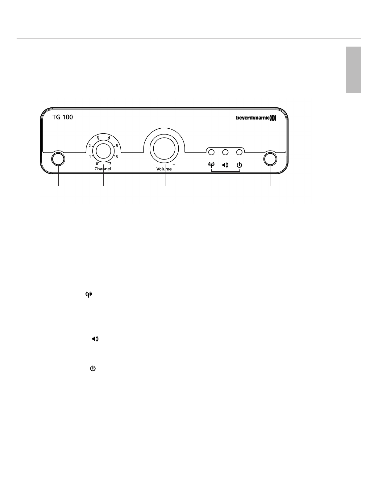
2.1 Bedien- und Kontrollelemente
Vorderseite
Ausziehbare Antennen A und B für Diversitybetrieb, fest montiert.
Kanalwahlschalter. Insgesamt stehen 8 Kanäle (0 - 7) zur Verfügung.
Lautstärkeregler für Audioausgang.
LED-Anzeigen.
Linke LED:
Grün dauerleuchtend: HF-Verbindung vorhanden. Batteriezustand Sender in Ordnung.
Rot dauerleuchtend: HF-Verbindung vorhanden. Batteriespannung vom Sender zu niedrig (low batt).
Grün blinkend: Kanal/Frequenz belegt durch anderen Sender oder Funkdienst auf dieser Frequenz.
Aus: Kanal frei, aber kein Sender eingeschaltet.
Mittlere LED:
Grün: Audiosignal vorhanden.
Rot: Übersteuerung (Audio Peak).
Rechte LED:
Grün: Empfänger eingeschaltet (Power on).
Page 8
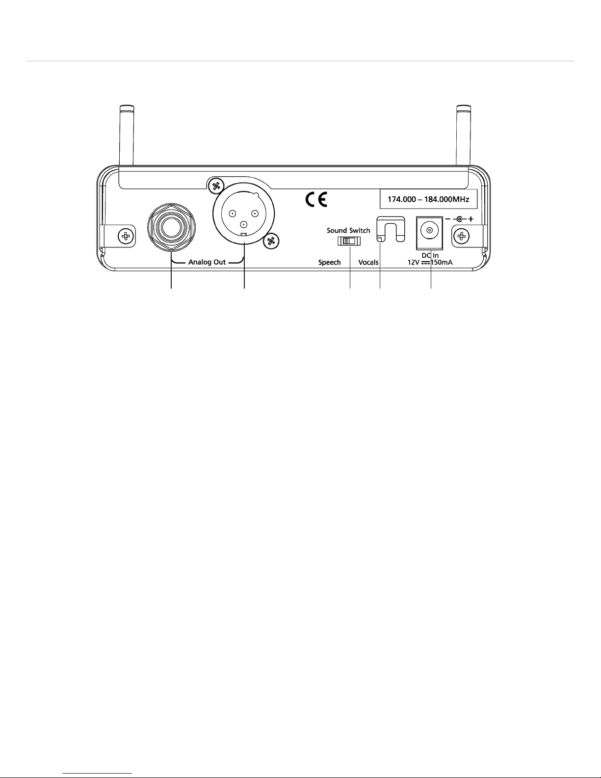
Audioausgang, 6,35 mm Klinke.
Audioausgang, 3-pol. XLR.
Umschalter „Sound Switch“
Position „Vocals“: neutrale Stellung für Gesang oder beim Anschluss einer Gitarre
Position „Speech“: für verbesserte Sprachverständlichkeit z.B. bei Reden, Ansagen
Aussparung im Gehäuse als Zugentlastung für Kabel des Netzteils.
12 V DC-Anschluss für Netzteil.
Wichtig: Verwenden Sie nur die von beyerdynamic lieferbaren oder empfohlenen Steckernetzteile.
Rückseite
TG 100 – Empfänger
8
Page 9

2.2 Inbetriebnahme des Empfängers
Empfänger positionieren
• Stellen Sie den Empfänger in dem Raum auf, in dem die Übertragung stattfindet.
• Stellen Sie den Empfänger so nahe wie möglich am Sender auf. Für einen optimalen Empfang ist
Sichtverbindung zwischen Sender und Empfänger anzustreben.
• Stellen Sie den Empfänger nicht unmittelbar neben digital gesteuerte Geräte.
Empfänger ans Netz anschließen
• Überprüfen Sie, ob die am Netzteil angegebene Netzspannung mit der Netzspannung am Einsatzort übereinstimmt.
Vorsicht: Der Betrieb des Gerätes an einer anderen Netzspannung kann zu irreparablen Schäden am
Gerät führen.
• Schließen Sie das mitgelieferte Steckernetzteil am DC-Anschluss und an einer Netzsteckdose
an. Der Empfänger hat keinen separaten Ein-/Ausschalter und ist sofort betriebsbereit, was auch
durch die grün leuchtende rechte LED angezeigt wird. Verwenden Sie kein anderes Steckernetzteil als das von beyerdynamic mitgelieferte bzw. empfohlene Steckernetzteil.
• Um den Empfänger vom Netz zu trennen, ziehen Sie das Netzteil aus der Netzsteckdose.
Antennen ausziehen
• Die Antennen sind fest auf der Vorderseite des Empfängers montiert. Ziehen Sie die Antennen ganz
aus und richten Sie sie V-förmig nach außen aus (ca. 60° Winkel). Eine Auswerteelektronik wählt
jeweils die Antenne, die das bessere Signal liefert.
Empfänger an einen Mikrofoneingang anschließen
• Der Empfänger verfügt über symmetrische Audioausgänge.
• Verbinden Sie den symmetrischen XLR- bzw. Klinken-Ausgang mit dem symmetrischen Mikrofoneingang am Mischpult oder Verstärker.
• Mit dem Lautstärkeregler können Sie den Pegel des Audioausgangs an den Eingangspegel des
Verstärkers bzw. des Mischpults anpassen.
Wichtig:
Ist der Pegel zu hoch eingestellt, können Verzerrungen des Audiosignals auftreten. Ist der Pegel zu
niedrig eingestellt, kann neben dem Audiosignal ein Rauschen auftreten.
Für erste Versuche empfehlen wir die Mittelstellung (Werkseinstellung).
Kanal auswählen / wechseln
• Mit dem Kanalwahlschalter können Sie einen von 8 Kanälen (0 - 7) am Empfänger auswählen.
Prüfen Sie am Empfänger, ob der von Ihnen gewünschte Kanal frei von Störungen ist (linke
LED darf nicht grün blinken bei ausgeschaltetem Sender).
Wichtig: Der Kanal des Empfängers muss mit dem des entsprechenden Senders übereinstimmen.
TG 100 – Empfänger
9
deutsch
Page 10
TG 100 – Taschensender
10
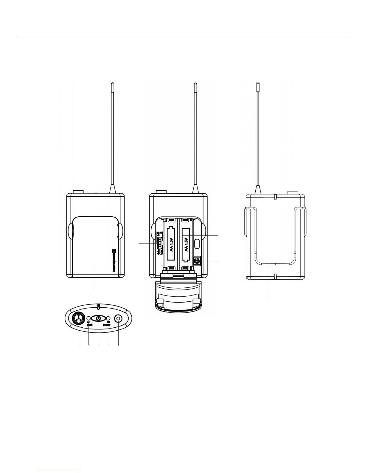
3. Taschensender TG 100B
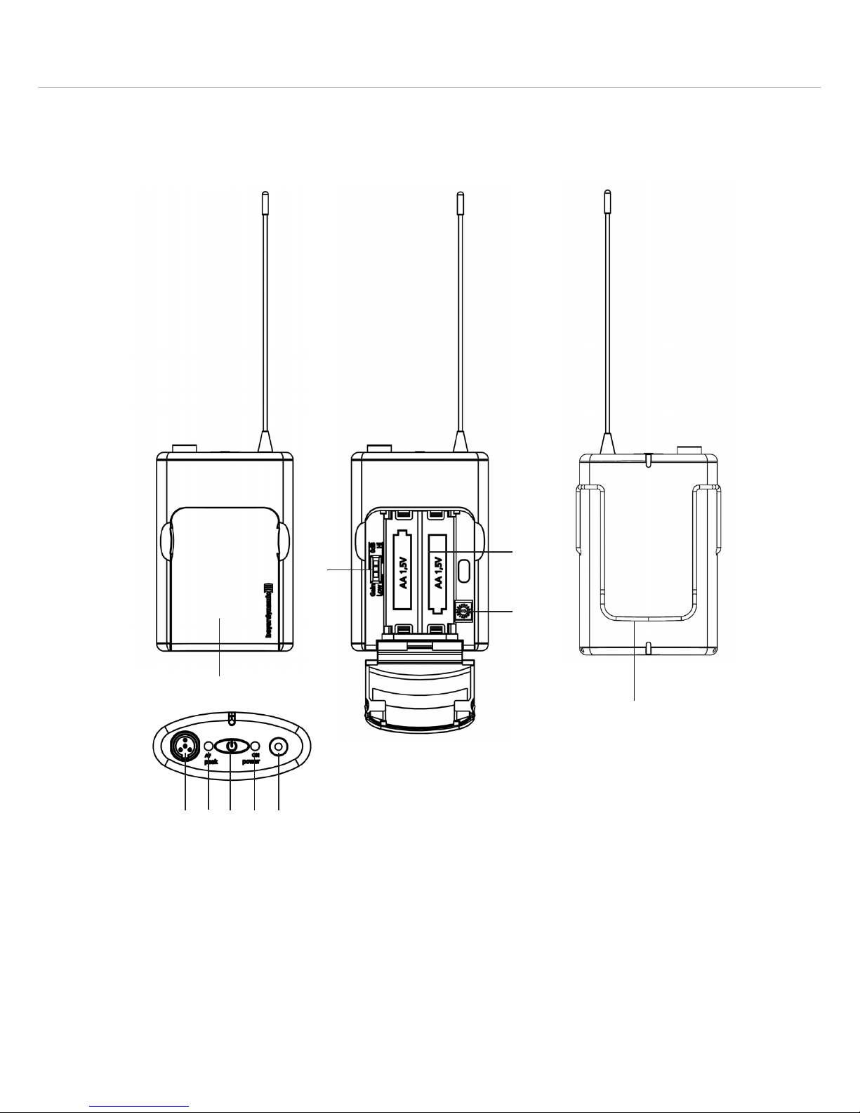
3.1 Bedien- und Kontrollelemente
4-pol. Mini-XLR-Einbaustecker (male) zum Anschluss vom Mikrofonen oder Instrumenten
LED zur Anzeige von Übersteuerungen
Ein-/Austaste
LED für Betriebsanzeige
Antenne, fest montiert
Batteriefachabdeckung
Empfindlichkeitsschalter Hi / 0 dB / Low
Batteriefach
Kanalwahlschalter
Gürtelclip
Page 11
deutsch
TG 100 – Taschensender
11
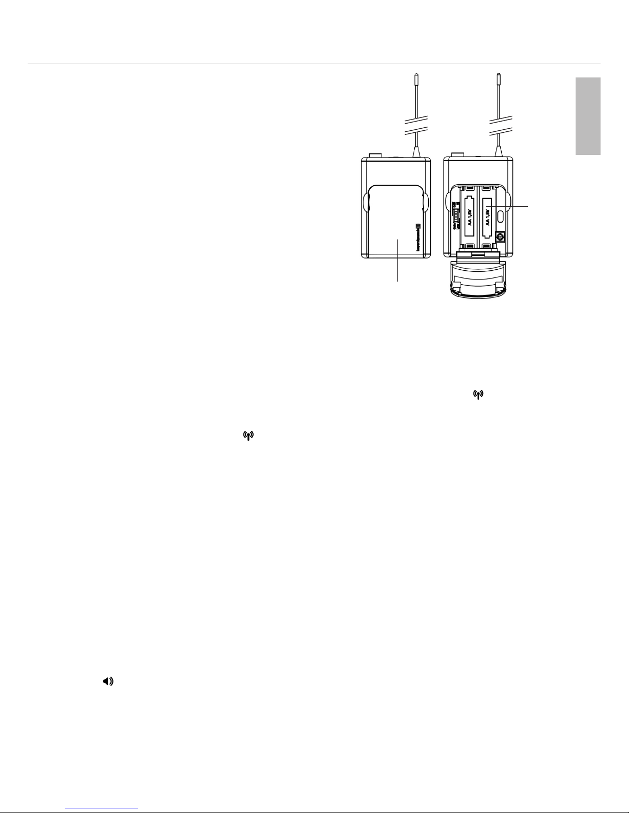
3.2 Inbetriebnahme des Taschensenders
Batterien einlegen / wechseln
• Fassen Sie die Batteriefachabdeckung oben rechts
und links an den seitlichen Einbuchtungen an.
• Klappen Sie die Batteriefachabdeckung nach
unten.
• Legen Sie zwei Alkaline-Batterien, AA, 1,5 V oder
NiMH-Akkus gemäß den Symbolen im Batteriefach
ein.
• Klappen Sie die Batteriefachabdeckung wieder nach
oben. Magnetverschlüsse sorgen für einen sicheren
Halt.
Headset anschließen
• Im Lieferumfang ist ein Headset enthalten, welches Sie bei Bedarf an den 4-pol. Mini-XLR-Einbaustecker anschließen können.
Ein-/Ausschalten
• Schalten Sie den Taschensender durch anhaltendes Drücken der Ein-/Austaste ein. Der Sender
ist betriebsbereit, wenn die LED für Betriebsanzeige grün leuchtet. Die linke LED am Empfänger leuchtet dauerhaft grün.
• Leuchtet die LED für Betriebsanzeige des Senders dauerhaft rot, sind die Batterien leer. Am
Empfänger leuchtet die linke LED dauerhaft rot. In diesem Fall sollten Sie die Batterien so
schnell wie möglich durch frische ersetzen bzw. die Akkus aufladen.
Kanal auswählen / wechseln
• Achten Sie darauf, dass Sender und Empfänger auf der gleichen Frequenz arbeiten. Schalten Sie
den Sender aus. Klappen Sie die Batteriefachabdeckung nach unten.
• Stellen Sie den Kanal des Senders mit einem kleinen Schraubendreher über den Kanalwahlschalter im Batteriefach entsprechend dem Kanal des Empfängers (0 - 7) ein.
• Zum Ausschalten des Taschensenders halten Sie die Ein-/Austaste einige Sekunden gedrückt, bis
die grüne LED für Betriebsanzeige erlischt.
Einstellung Empfindlichkeit
• Mit dem Empfindlichkeitsschalter („Gain“) kann die Empfindlichkeit für Nah- oder Fernbesprechung eingestellt werden:
– Position „Low“ für laute Nahbesprechung bzw. bei Anschluss einer Gitarre.
– Position „Hi“ für Fernbesprechung.
– Position „0 dB“ für Standardbesprechung.
• Stellen Sie die Empfindlichkeit so ein, dass bei lauten Passagen am Empfänger die mittlere
LED wenn überhaupt, dann nur kurz rot aufleuchtet.
Befestigen des Gürtelclips
• Im Lieferumfang des Taschensenders ist ein Gürtelclip enthalten, mit dem Sie den Taschensender
an der Kleidung, am Gürtel, am Gitarrengurt usw. befestigen können.
• Sie können den Gürtelclip entfernen, indem Sie ihn seitlich vom Taschensender aus seiner Befestigung herausziehen.
Page 12

TG 100 – Taschensender
12
3.3 Hinweise für den störungsfreien Betrieb
Batterie / Akku
• Überprüfen Sie den Ladezustand der Senderbatterie(n) und ersetzen Sie ggf. die Batterie(n). Verwenden Sie nur neuwertige Alkalinebatterien bzw. laden Sie die Akkus auf.
• Schalten Sie den Sender vor dem Batteriewechsel aus.
• Wenn Sie den Sender für Wochen oder Monate nicht benutzen, entfernen Sie bitte Akkus/Batterien
aus dem Sender. Akkus/Batterien können nach längerem Nichtgebrauch auslaufen und Leiterbahnen und Bauteile zerfressen. Eine Reparatur ist dann nicht mehr möglich. In diesem Fall entfallen
alle Garantieansprüche. Auch die Bezeichnung „Leak proof“ auf Akkus/Batterien ist keine Garantie gegen Auslaufen.
• Die Batteriekontakte sollten Sie von Zeit zu Zeit mit einem mit Spiritus oder Alkohol befeuchtetem,
weichen Tuch reinigen.
• Werfen Sie verbrauchte Akkus/Batterien nicht in den Hausmüll, sondern geben Sie diese an den örtlichen Sammelstellen ab.
• Zum Laden von Akkus verwenden Sie handelsübliche Akkuladegeräte.
Empfang
• Überprüfen Sie, ob Sender und Empfänger auf der gleichen Frequenz arbeiten.
• Die Reichtweite des Systems hängt von den örtlichen Gegebenheiten ab und kann bis zu 100 m
betragen. Zwischen Sender und Empfänger sollten Sie einen Mindestabstand von 1 m einhalten.
• Schreiten Sie den Bereich ab, in dem der Sender eingesetzt werden soll. Achten Sie dabei auf
Stellen, wo die Feldstärke absinkt („Dropouts“) und der Empfang gestört ist (linke LED am Empfänger erlischt). Solche „Dropouts“ können Sie durch Verändern der Antennenposition beheben.
Zwischen Sende- und Empfangsantenne sollte freie Sicht herrschen und nicht durch Hindernisse
blockiert werden.
Allgemein
• Pegeln Sie Empfänger und ggf. Sender richtig ein, um Verzerrungen zu vermeiden.
• Achten Sie beim Soundcheck auf Rückkopplungen.
Page 13

deutsch
TG 100 – Problemlösung
13
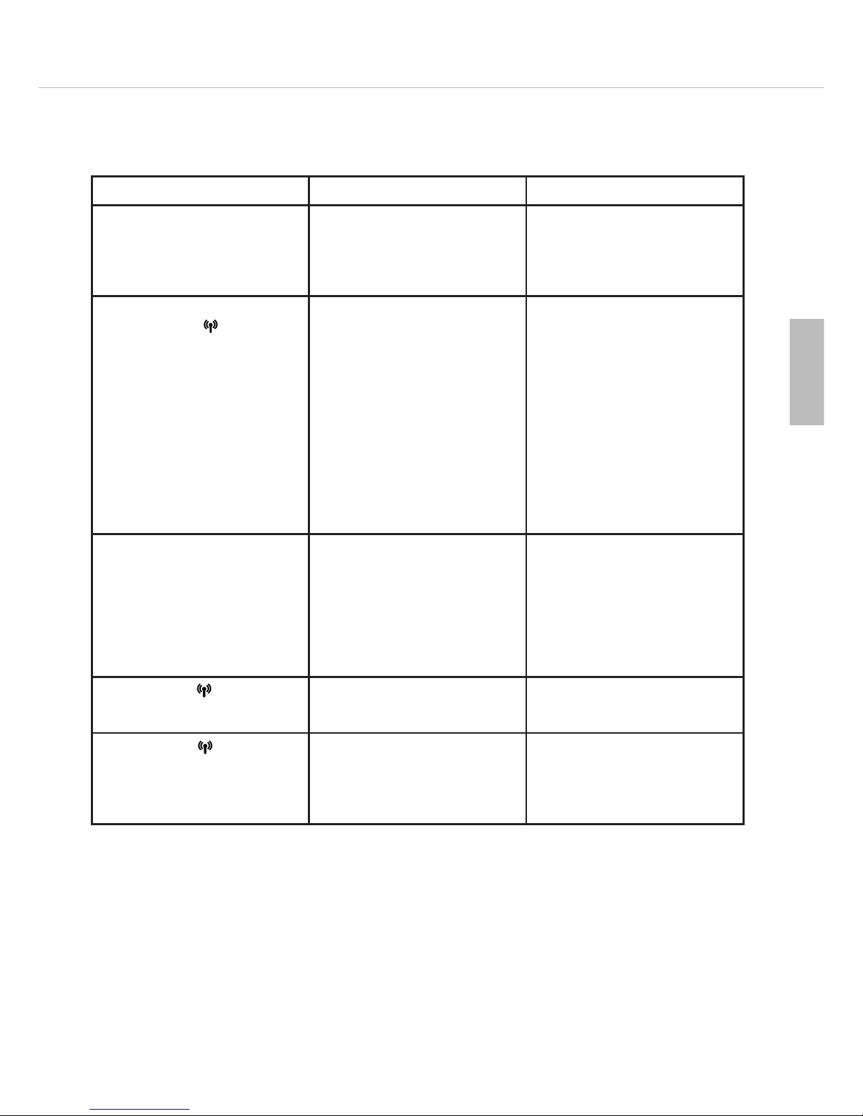
Problem Mögliche Ursache Lösung
Keine Funktion • Stromversorgung unter-
brochen. Steckernetzteil ist
nicht an der Steckdose und/
oder am Empfänger angeschlossen.
• Steckernetzteil an Steckdose und / oder am Empfänger anschließen.
Kein Empfang
(linke LED leuchtet
nicht)
• Sender ist nicht eingeschaltet.
• Sender hat eine andere
Frequenz.
• Empfangsantennen sind
nicht richtig positioniert.
• Außerhalb der Funkreichweite; Abstand zwischen
Sender und Empfänger zu
groß.
• Sender einschalten.
• Sendefrequenz muss mit
Empfangsfrequenz übereinstimmen.
• Ziehen Sie die Antennen
ganz aus und richten Sie sie
V-förmig nach außen aus
(ca. 60° Winkel).
• Verringern Sie den Abstand
zwischen Sender und Empfänger.
Ton verzerrt • Eingangsverstärker des
nachgeschalteten Mixers ist
übersteuert.
• Eingangsempfindlichkeit zu
hoch.
• Absenkung am Mixer benutzen oder mit Lautstärkeregler nachsteuern.
• Empfindlichkeit absenken,
d.h. Schalter „Gain“ des
Senders auf Position „0 dB“
oder „Low“ stellen.
Linke LED leuchtet dauerhaft rot
• Batterie vom Sender zu
schwach.
• Wechseln Sie die Batterie
bzw. laden Sie den Akku
wieder auf.
Linke LED blinkt grün
• Funkkanal gestört • Wählen Sie am Empfänger
und Sender eine andere
Frequenz (Kanal).
4. Problemlösung
Diversityempfänger TG 100R
Page 14

TG 100 – Problemlösung
14
Problem Mögliche Ursache Lösung
Keine Funktion bzw.
Betriebskontroll-LED leuchtet
nicht
• Ungenügende Batteriespannung.
• Unzureichender Batteriekontakt, Batterie falsch eingelegt.
• Wechseln Sie die Batterie
aus bzw. laden Sie den Akku
wieder auf.
• Überprüfen Sie die Batterie
und legen Sie sie ggf. neu
ein.
Störgeräusche / „Zwitschern“ • Interferenzstörung durch
weitere Sender.
• Zwei Sender auf der
gleichen Frequenz.
• Schalten Sie die anderen
Sender aus.
• Vermeiden Sie, zwei Sender
mit der gleichen Frequenz
einzusetzen.
Taschensender TG 100B
5. Ausführungen
TG 100 Beltpack Set bestehend aus: Diversityempfänger und Taschensender,
Band 1, 174 - 184 MHz. . . . . . . . . . . . . . . . . . . . . . . Best.-Nr. 706.329
dito, jedoch Band 2, 194 - 204 MHz. . . . . . . . . . . . . . Best.-Nr. 706.337
dito, jedoch Band 3, 213 - 223 MHz. . . . . . . . . . . . . . Best.-Nr. 706.345
TG 100 Handheld Set bestehend aus: Diversityempfänger und Handsender,
Band 1, 174 - 184 MHz. . . . . . . . . . . . . . . . . . . . . . . Best.-Nr. 706.264
dito, jedoch Band 2, 194 - 204 MHz. . . . . . . . . . . . . . Best.-Nr. 706.272
dito, jedoch Band 3, 213 - 223 MHz. . . . . . . . . . . . . . Best.-Nr. 706.280
6. Zubehör
Lieferumfang
Empfänger TG 100R mit Steckernetzteil
Taschensender TG 100B mit Headset TG H34c
Optional
Taschensender TG 100B
Mikrofone
TG L55c Miniaturkondensatoransteckmikrofon, Kugel, wasserfest,
mit 4-pol. Mini-XLR Anschluss, schwarz . . . . . . . . . . . . . . . . Best.-Nr. 707.201
TG L55c tan dito, jedoch beige . . . . . . . . . . . . . . . . . . . . . . . . . . . . . . . . Best.-Nr. 707.228
TG H34c Kondensator-Headsetmikrofon, Niere, schwarz,
mit 4-pol. Mini-XLR-Anschluss . . . . . . . . . . . . . . . . . . . . . . . Best.-Nr. 706.396
TG H54c Kondensator-Headsetmikrofon, Niere, schwarz,
mit 4-pol. Mini-XLR-Anschluss . . . . . . . . . . . . . . . . . . . . . . . Best.-Nr. 707.058
TG H54c tan dito, jedoch beige . . . . . . . . . . . . . . . . . . . . . . . . . . . . . . . . Best.-Nr. 707.066
TG H55c Kondensator-Headsetmikrofon, Kugel, schwarz,
mit 4-pol. Mini-XLR-Anschluss . . . . . . . . . . . . . . . . . . . . . . . Best.-Nr. 707.074
TG H55c tan dito, jedoch beige . . . . . . . . . . . . . . . . . . . . . . . . . . . . . . . . Best.-Nr. 707.082
Page 15

deutsch
TG 100 – Technische Daten
15
TG H74c Nackenbügelmikrofon, Kondensator, Niere,
4-pol. Mini-XLR-Anschluss, schwarz . . . . . . . . . . . . . . . . . . . Best.-Nr. 707.090
TG H74c tan dito, jedoch beige . . . . . . . . . . . . . . . . . . . . . . . . . . . . . . . . Best.-Nr. 707.104
TG H75c Nackenbügelmikrofon, Kondensator, Kugel, wasserfest,
4-pol. Mini-XLR-Anschluss, schwarz . . . . . . . . . . . . . . . . . . . Best.-Nr. 707.112
TG H75c tan dito, jedoch beige . . . . . . . . . . . . . . . . . . . . . . . . . . . . . . . . Best.-Nr. 707.120
Kabel
WA-CGI Verbindungskabel zum Anschluss von Instrumenten
mit 6,35 mm Monoklinkenstecker . . . . . . . . . . . . . . . . . . . . Best.-Nr. 711.608
7. Technische Daten
Diversityempfänger TG 100R
Funktionsprinzip. . . . . . . . . . . . . . . . . . . . Diversityempfänger
Frequenzbereiche . . . . . . . . . . . . . . . . . . . Band 1 = 174 - 184 MHz,
Band 2 = 194 - 204 MHz
Band 3 = 213 - 223 MHz
Übertragungsbereich. . . . . . . . . . . . . . . . . 100 Hz - 16 kHz
Aussteuerungsbereich . . . . . . . . . . . . . . . . 94 dB
Ausgangspegel . . . . . . . . . . . . . . . . . . . . . max. 0 dBV
Netzanschluss . . . . . . . . . . . . . . . . . . . . . 100 V – 240 V AC; Steckernetzteil 12V DC
Stromverbrauch . . . . . . . . . . . . . . . . . . . . 150 mA
Umgebungstemperatur . . . . . . . . . . . . . . . 0 bis +55 °C
Gewicht. . . . . . . . . . . . . . . . . . . . . . . . . . 250 g
Abmessungen. . . . . . . . . . . . . . . . . . . . . . 140 x 80 x 39 mm
Antennenanschluss. . . . . . . . . . . . . . . . . . 2 x ausziehbare, fest angeschlossene Antennen
Taschensender TG 100B
Frequenzbereiche . . . . . . . . . . . . . . . . . . . Band 1 = 174 - 184 MHz,
Band 2 = 194 - 204 MHz
Band 3 = 213 - 223 MHz
Übertragungsbereich. . . . . . . . . . . . . . . . . 100 Hz - 16 kHz
Sendeleistung . . . . . . . . . . . . . . . . . . . . . < 10 mW erp
Dynamikbereich . . . . . . . . . . . . . . . . . . . . 110 dB
Übertragungsreichweite. . . . . . . . . . . . . . . bis zu 100 Meter bei optimalen Bedingungen
Betriebsdauer. . . . . . . . . . . . . . . . . . . . . . ca. 8 Std. (NiMH 2100 mAh)
Eingangspegel . . . . . . . . . . . . . . . . . . . . . max. 1,2 V rms
Gewicht. . . . . . . . . . . . . . . . . . . . . . . . . . 102 g ohne Batterien
Abmessungen. . . . . . . . . . . . . . . . . . . . . . 94x59x26 mm
Belegung 4-pol. Anschlussbuchse . . . . . . . Stift 1 = Masse, Stift 2 = IN1,
Stift 3 = IN2, Stift 4 = +5
Anschlussbelegung Headset
Page 16

TG 100 – Zulassung
16
9. Zulassung und Anmeldepflicht
Um einen möglichst störungsfreien Betrieb mit anderen Funkdiensten (z.B. Fernsehen und Radio) zu
ermöglichen, werden drahtlosen Mikrofonen und In-Ear-Monitoring-Systemen bestimmte Frequenzen
und Sendeleistungen zugeteilt. In Deutschland sind dafür die Außenstellen der Bundesnetzagentur
(www.bundesnetzagentur.de) zuständig.
Wichtig:
Drahtlossysteme benötigen eine Sendelizenz und sind anmelde- und gebührenpflichtig.
Lizenzpflichtig und damit gebührenpflichtig sind in Deutschland alle Funkmikrofone im Bereich
174-216 MHz.
Aktuelle Informationen über die Bestimmungen zum Betrieb von Drahtlossystemen finden Sie
auf: www.bundesnetzagentur.de
Die Komponenten des TG 100 Systems sind gemäß EU-Richtlinie R&TTE 99/5/EEC wie folgt zugelassen:
Taschensender „TG 100B Beltpack Transmitter“
Handsender „TG 100H Handheld Transmitter“
unter der Kennzeichnung CE 0681 !
8. Service
Im Servicefall wenden Sie sich bitte an autorisiertes Fach personal. Öffnen Sie das Gerät auf keinen
Fall selbst, Sie könnten sonst alle Gewährleistungsansprüche verlieren.
Page 17

deutsch
TG 100 – Notizen
17
Page 18

Page 19

english
TG 100 – Contents
19
1. Safety Instructions . . . . . . . . . . . . . . . . . . . . . . . . . . . . . . . . . . . . . . . Page 20
1.1 TG 100B Beltpack Transmitter. . . . . . . . . . . . . . . . . . . . . . . . . . Page 21
1.2 NiMH Rechargeable Batteries, Alkaline Batteries. . . . . . . . . . . . . Page 22
1.3 Disposal. . . . . . . . . . . . . . . . . . . . . . . . . . . . . . . . . . . . . . . . . . Page 22
2. TG 100R Diversity Receiver . . . . . . . . . . . . . . . . . . . . . . . . . . . . . . . . Page 23
2.1 Controls and Indicators . . . . . . . . . . . . . . . . . . . . . . . . . . . . . . . Page 23
2.2 How to Operate the Receiver . . . . . . . . . . . . . . . . . . . . . . . . . . . Page 25
3. TG 100B Beltpack Transmitter . . . . . . . . . . . . . . . . . . . . . . . . . . . . . . Page 26
3.1 Controls and Indicators . . . . . . . . . . . . . . . . . . . . . . . . . . . . . . . Page 26
3.2 How to Operate the Beltpack Transmitter . . . . . . . . . . . . . . . . . . Page 27
3.3 Tips for an Interference-free Operation . . . . . . . . . . . . . . . . . . . . Page 28
4. Trouble Shooting . . . . . . . . . . . . . . . . . . . . . . . . . . . . . . . . . . . . . . . . Page 29
5. Versions . . . . . . . . . . . . . . . . . . . . . . . . . . . . . . . . . . . . . . . . . . . . . . Page 30
6. Accessories . . . . . . . . . . . . . . . . . . . . . . . . . . . . . . . . . . . . . . . . . . . . Page 30
7. Technical Specifications . . . . . . . . . . . . . . . . . . . . . . . . . . . . . . . . . . . Page 31
8. Service . . . . . . . . . . . . . . . . . . . . . . . . . . . . . . . . . . . . . . . . . . . . . . . Page 32
9. Licensing . . . . . . . . . . . . . . . . . . . . . . . . . . . . . . . . . . . . . . . . . . . . . Page 32
10. FCC Regulation . . . . . . . . . . . . . . . . . . . . . . . . . . . . . . . . . . . . . . . . . Page 32
Page 20

TG 100 – Safety
20
Thank you for selecting the TG 100 wireless system from beyerdynamic.
Please take some time to read carefully through this manual before setting up the equipment.
The TG 100 system operates with 8 selectable frequencies in the VHF frequency range and is available
in two sets and different frequency ranges:
1. Diversity receiver and handheld transmitter
2. Diversity receiver and beltpack transmitter including headset
1. Safety Instructions
1. Read these instructions.
2. Keep these instructions.
3. Heed all warnings.
4. Follow all instructions.
5. Do not use this apparatus near water.
6. Clean only with a dry cloth.
7. Do not install near any heat sources such as radiators, heat registers, stoves or other apparatus
(including amplifiers) that produce heat.
8. Do not modify the power plug of this apparatus.
9. Protect the power cord from being walked on or pinched particularly at plugs, convenience
receptacles, and the point where they exit from the apparatus.
10. Only use attachments/accessories specified by the manufacturer.
11. Unplug this apparatus during lightning storms or when unused for long periods of time.
12. Refer all servicing to qualified service personnel. Servicing is required when the apparatus has
been damaged in any way, such as power supply cord or plug is damaged, liquid has been
spilled or objects have fallen into the apparatus, the apparatus has been exposed to rain or
moisture, does not operate normally, or has been dropped.
Exemption from liability
• beyerdynamic GmbH & Co. KG will not be liable if any damage, injury or accident occurs due to
negligent, incorrect or inappropriate operation of the prodcuts.
Location
• The equipment must be set up so that the power connection, power supply and all connections on
the rear of the device are easily accessible.
• If you transport the equipment to another location, take care to ensure that it is adequately
secured an can never be damaged by being dropped or by impacts on the equipment.
Fire hazard
• Never place naked flames (e.g. candles) near the equipment.
Humidity / heat sources
• Never expose the equipment to rain or a high level of humidity. For this reason do not install it in
the immediate vicinity of swimming pools, showers, damp basement rooms or other areas with
unusually high atmospheric humidity.
• Never place objects containing liquid (e.g. vases or drinking glasses) on the equipment. Liquids in
the equipment could cause a short circuit.
• Do not install near any heat sources such as radiators, heat registers, stoves or other apparatus
(including amplifiers) that produce heat.
Page 21

english
TG 100 – Safety
21
Connection
• Protect all cables from being walked on or pinched particularly at plugs, convenience receptacles,
and the point where they exit from the apparatus.
• Lay all connection cables so that they do not present a trip hazard.
• Whenever working on the inputs and outputs of the equipment switch off power.
• Check whether the connection figures comply with the existing mains supply. Serious damage could
occur due to connecting the system to the wrong power supply. An incorrect mains voltage could
damage the equipment or cause an electric shock.
• Please note that different operating voltages require the use of different types of power supplies.
Please refer to the following table:
• If the equipment causes a blown fuse or a short circuit, disconnect it from the mains and have it
checked and repaired.
• Do not hold the power supply with wet hands. There must be no water or dust on the contact pins.
In both cases you could receive an electric shock.
• The power cable must be firmly connected. If it is loose there is a fire hazard.
• Always pull out the power supply from the mains and/or from the equipment by the plug – never by
the cable. The cable could be damaged and cause an electric shock or fire.
• Do not use the equipment if the power adapter is damaged.
• If you connect defective or unsuitable accessories, the equipment could be damaged. Only use
power adapters available from or recommended by beyerdynamic.
• In order to disconnect the receiver from AC power, disconnect the power plug from the power socket.
Maintenance
• Only clean the equipment with a slightly damp or dry cloth. Never use solvents as these damage
the surface.
Trouble shooting and servicing
• Do not open the equipment without authorisation. You could receive an electric shock. There are
no user-serviceable parts inside.
• Leave all service work to authorised expert personnel.
1.1 TG 100B Beltpack Transmitter
• Protect the transmitter from moisture and sudden impacts. You could either injure yourself or
others or damage the transmitter.
• Always switch off the transmitter before changing the battery.
• Clip-on microphones are often very compact. If they are accidentally swallowed there is a risk of
choking. Always keep this type of microphone away from small children.
Voltage Power plug according to standard
110 - 125 V UL817 and CSA C 22.2 no 42.
220 - 230 V CEE 7 page VII, SR section 107-2-D1/IEC 83 page C4.
240 V BS 1363 (1984): “Specification for 13A fused plugs and switched and un-switched socket
outlets.”
Page 22

TG 100 – Safety
22
1.2 NiMH Rechargeable Batteries, Alkaline Batteries
• The handheld and beltpack transmitters of the TG 100 system can only be powered with AA (LR6)
Mignon alkaline batteries or equivalent NiMH rechargeable batteries.
• The normal commercial alkaline batteries can have a length tolerance of 2 - 3 mm. When changing
the battery always ensure good contact.
• If the transmitter is not being used for weeks or months, please remove the batteries. Batteries can
leak when not being used for a long time and corrode the conductor strips and components.
Repair is not then possible. In this case all warranty claims are null and void. The description
“leak proof” on batteries is no guarantee that they will not run out.
• Never take batteries apart yourself. The battery acid contained will damage skin and clothing.
• If abused or misused, rechargeable batteries may leak. In extreme cases, they may even present an
explosion, heat, fire, smoke or gas hazard.
• Never expose batteries to excessive heat such as sunshine, fire or the like.
1.3 Disposal
• If you throw away the transmitter, please remove the batteries.
• Old batteries may contain substances that are harmful to your health and environment.
• Dispose used batteries always according to the applicable disposal regulations. Please do not throw
used battery packs into the fire (danger of explosion) or your household rubbish, take them to your
local collection points. The return is free and required by law. Please dispose discharged batteries
only.
• For removing the batteries, please refer to chapter “How to insert/replace the batteries“.
• All batteries are recycled to reclaim valuable material such as iron, zinc or nickel.
• This symbol on the product, in the instructions or on the packaging means that your
electrical and electronic equipment should be disposed at the end of its life separately
from your household waste. There are separate collection systems for recycling in the EU.
For more information, please contact the local authority or your retailer where you
purchased the product.
Page 23

english
TG 100 – Receiver
23
2. TG 100R Diversity Receiver
2.1 Controls and Indicators
Front view
Telescopic antennae A and B for diversity operation, permanently attached.
Channel selector switch. In total there are 8 channels (0 - 7) available.
Volume control for audio output.
LEDs.
Left LED:
Illuminated permanently green: RF connection available. Battery of the transmitter is alright.
Illuminated permanently red: RF connection available. Battery voltage of the transmitter is too low
(low batt).
Flashing green: Channel/frequeny is occupied by another transmitter or radio service on this
frequency.
Off: Channel is vacant, but the transmitter is not turned on.
Middle LED:
Green: Audio signal is available.
Red: Audio peak, only with loud passages.
Right LED:
Green: Receiver is turned on (Power on).
Page 24

TG 100 – Receiver
24
Audio output, 1/4" jack (6.35 mm).
Audio output, 3-pin XLR.
Sound switch
Position “Vocals”: neutral position for vocals or when using a guitar
Position “Speech”: for improved intelligibility of speech, e.g. speeches, announcements
Recess in the housing as strain relief for cable of the power supply.
12 V DC connection for the power supply.
Important: Do not use any other power supply, only the one supplied or recommended by
beyerdynamic.
Rear view
Page 25

english
TG 100 – Receiver
25
2.2 How to Operate the Receiver
Where to place the receiver
• Place the receiver in the same room where the transmission takes place.
• Place the receiver as close as possible to the transmitter. For optimal reception, a free line of sight
is advisable between transmitter and receiver.
• Do not place the receiver near digitally controlled devices.
How to connect the receiver to the mains
• Verify that the voltage rating of the power supply matches that of the mains outlet that you are
using.
Warning: If you connect the receiver to the wrong voltage, you may cause damage.
• Connect the supplied power supply to the DC connection and to a mains socket. The receiver
has no separate on-off switch and will immediately be ready for operation indicated by the right
LED illuminating green. Do not use any other power supply, only the one supplied or
recommended by beyerdynamic.
• To disconnect the receiver from the mains, pull the power supply out of the mains socket.
How to extend the antennae
• The antennae are permanently attached on the front of the receiver. Extend the antennae completely
and set them at an angle (approx. 60°) in the shape of a “V”. A weighting circuit ensures that an
antenna is selected that supplies the better signal.
How to connect the receiver to a microphone input
• The receiver is provided with balanced audio outputs.
• Connect the balanced XLR or jack output to the balanced microphone input of a mixing
console or amplifier.
• Adjust the level of the audio output to the input level of the amplifier or mixing console by using
the volume control .
Important:
If the level is set too high, the audio signal will be distorted. If the level is set too low, it will result
in an audio signal with high background noise.
We recommend the middle position (factory setting) for first tries.
How to select or change a channel
• With the channel selector switch you can select one of 8 channels (0 - 7).
Check the receiver, if the selected channel is free from interference (left LED must not flash
green when the transmitter is turned off).
Important: The channel of the receiver must match the channel of the appropriate transmitter.
Page 26
TG 100 – Beltpack Transmitter
26
3. TG 100B Beltpack Transmitter
3.1 Controls and Indicators
4-pin mini XLR connector (male) to connect microphones or instruments
AF peak LED
On-off button
Power on LED
Antenna, permanently attached
Cover of battery compartment
Gain switch Hi / 0 dB / Low
Battery compartment
Channel selector switch
Belt clip
Page 27

english
TG 100 – Beltpack Transmitter
27
3.2 How to Operate the Beltpack Transmitter
How to insert or change the batteries
• Take hold of the cover of the battery compartment
on top at the inlets at the right and left hand side.
• Flap the cover of the battery compartment
downwards.
• Insert two alkaline batteries, AA 1.5 V or rechargeable NiMH batteries according to the symbols in the
battery compartment .
• Flap the cover of the battery compartment upwards to close. Magnets ensure a secure fastening.
How to connect a headset
• The transmitter is supplied with a headset which you can connect to the 4-pin mini XLR
connector .
How to turn the transmitter on or off
• Turn on the beltpack transmitter by holding the on-off button pressed. The transmitter is ready
for operation when the power on LED will illuminate green. The left LED on the receiver
will permanently illuminate green.
• If the power on LED of the transmitter will permanently illuminate red, the batteries are empty.
The left LED on the receiver will permanently illuminate red. In this case, you should replace
the batteries as soon as possible by new ones or recharge the rechargeable batteries.
How to select or change a channel
• Make sure that transmitter and receiver operate on the same frequency. Switch off the transmitter.
Flap the cover of the battery compartment downwards.
• Select the channel of the transmitter with the channel selector switch in the battery compartment according to the channel of the receiver (0 - 7) by using a small screwdriver.
• In order to turn off the beltpack transmitter hold the on-off button pressed for a few seconds, until
the green power on LED will go out.
How to adjust the sensitivity
• With the gain switch you can adjust the sensitivity for close or distant miking:
– Position “Low” for close miking or when connecting a guitar.
– Position “Hi” for distant miking.
– Position “0 dB” for standard miking.
• Adjust the sensitivity so that the middle LED of the receiver does not, or only briefly, light up
red during loud tones.
How to mount the belt clip
• The beltpack transmitter is supplied with a belt clip to attach the transmitter to clothes, belts, a
guitar strap etc.
• You can remove the belt clip by pulling it from the fixation of the beltpack transmitter.
Page 28

TG 100 – Beltpack Transmitter
28
3.3 Tips for an Interference-free Operation
Battery / rechargeable battery
• Check the transmitter battery and replace or recharge it if necessary. Use fresh alkaline batteries only
or recharge the rechargeable batteries.
• Switch off the transmitter before changing the batteries.
• If the transmitter is not being used for weeks or months, please remove the batteries. Batteries can
leak when not being used for a long time and corrode the conductor strips and components. Repair
is not possible. In this case all warranty claims are null and void. The description “leak proof” on
batteries is no guarantee that they will not run out.
• From time to time the battery contacts should be cleaned with a soft cloth moistened with spirits or
alcohol.
• Do not throw used batteries into the domestic rubbish, but hand them in to local collection points.
• For charging rechargeable batteries use standard battery chargers.
Reception
• Make sure that the transmitter and receiver are on the same frequency
• The range of the system depends on local conditions and can be up to 100 metres. The distance
between transmitter and receiver should be at least 1 metre.
• Check the performance area for dropouts (i.e. areas where poor reception is encountered). If you find
any dropouts (left LED of the receiver goes out) try to eliminate them by repositioning the
antennae or the receiver. Make sure that there is free line of sight between transmitting and receiving
antennae.
General
• Adjust the level of the receiver and transmitter properly to avoid distortions.
• Mind feedback during the sound check.
Page 29

english
TG 100 – Trouble Shooting
29
4. Trouble Shooting
TG 100R diversity receiver
Problem Possible cause Solution
No function • Power supply is interrupted.
Power supply unit is not
connected to the mains
and/or to the receiver.
• Connect the power supply
unit to the mains and/or to
the receiver.
No reception
(left LED does not
illuminate)
• Transmitter is not switched
on.
• Transmitter works on a
different frequency.
• Receiving antennae are not
positioned correctly.
• Out or range; distance
between transmitter and
receiver is too far.
• Switch on the transmitter.
• Make sure that the transmitter and receiver are on
the same frequency.
• Extend the antennae
completely and set set them
at an angle (approx. 60°) in
the shape of a “V”.
• Reduce the distance
between transmitter and
receiver
Distorted sound • Input amplifier of the
connected mixer is overloaded.
• Input sensitivity is too high.
• Use the reduction of the
mixer or adjust the
volume .
• Reduce the sensitivity, i.e.
set the gain switch of the
transmitter to “0 dB” or
“Low”.
Left LED illuminates
permanently red
• Battery of the transmitter is
too weak.
• Replace the battery or
recharge the rechargeable
battery.
Left LED is flashing
green
• Disturbed channel. • Select another frequency
(channel) for the receiver
and transmitter.
Page 30

TG 100 – Accessories
30
Problem Possible cause Solution
No function or on-off button
does not illuminate
• Insufficient battery voltage.
• Insufficient battery contact,
battery inserted incorrectly.
• Replace the battery or
recharge the rechargeable
battery.
• Check the battery and insert
it again.
Noise / chirping • Interference from other
transmitters.
• Two transmitters using the
same frequency.
• Switch off the other
transmitters.
• Avoid using two transmitters
with the same frequency.
TG 100B beltpack transmitter
5. Versions
TG 100 Beltpack Set consisting of: diversity receiver and beltpack transmitter,
band 1, 174 - 184 MHz . . . . . . . . . . . . . . . . . . . . . . . Order # 706.329
same as above, but band 2, 194 - 204 MHz. . . . . . . . . Order # 706.337
same as above, but band 3, 213 - 223 MHz. . . . . . . . . Order # 706.345
TG 100 Handheld Set consisting of: diversity receiver and handheld transmitter,
band 1, 174 - 184 MHz . . . . . . . . . . . . . . . . . . . . . . . Order # 706.264
same as above, but band 2, 194 - 204 MHz. . . . . . . . . Order # 706.272
same as above, but band 3, 213 - 223 MHz. . . . . . . . . Order # 706.280
6. Accessories
Supplied accessories
TG 100R receiver with power supply unit
TG 100B beltpack transmitter with TG H34c headset
Optional
TG 100B Beltpack transmitter
Microphones
TG L55c Miniature condenser clip-on microphone, omnidirectional,
water-resistant, with 4-pin mini XLR connector, black . . . . . . . Order # 707.201
TG L55c tan same as above, but beige. . . . . . . . . . . . . . . . . . . . . . . . . . . Order # 707.228
TG H34c Condenser headset microphone, cardioid, black,
with 4-pin mini XLR connector . . . . . . . . . . . . . . . . . . . . . . . Order # 706.396
TG H54c Condenser headset microphone, cardioid, black,
with 4-pin mini XLR connector . . . . . . . . . . . . . . . . . . . . . . . Order # 707.058
TG H54c tan same as above, but beige . . . . . . . . . . . . . . . . . . . . . . . . . . . Order # 707.066
TG H55c Condenser headset microphone, omnidirectional, black,
with 4-pin mini XLR connector . . . . . . . . . . . . . . . . . . . . . . . Order # 707.074
TG H55c tan same as above, but beige . . . . . . . . . . . . . . . . . . . . . . . . . . . Order # 707.082
Page 31

english
TG 100 – Technical Specifications
31
TG H74c Neckworn microphone, condenser, cardioid,
4-pin mini XLR connector, black. . . . . . . . . . . . . . . . . . . . . . Order # 707.090
TG H74c tan same as above, but beige . . . . . . . . . . . . . . . . . . . . . . . . . . . Order # 707.104
TG H75c Neckworn microphone, condenser, omnidirectional,
water-resistant, 4-pin mini XLR connector, black . . . . . . . . . . Order # 707.112
TG H75c tan same as above, but beige . . . . . . . . . . . . . . . . . . . . . . . . . . . Order # 707.120
Cable
WA-CGI Connecting cable to connect instruments
with a mono 1/4" jack plug. . . . . . . . . . . . . . . . . . . . . . . . . . Order # 711.608
7. Technical Specifications
TG 100R diversity receiver
Operating principle . . . . . . . . . . . . . . . . . . Diversity receiver
Frequency range. . . . . . . . . . . . . . . . . . . . Band 1 = 174 - 184 MHz,
Band 2 = 194 - 204 MHz
Band 3 = 213 - 223 MHz
Frequency response . . . . . . . . . . . . . . . . . 100 Hz - 16 kHz
Dynamic range . . . . . . . . . . . . . . . . . . . . . 94 dB
Output level . . . . . . . . . . . . . . . . . . . . . . . max. 0 dBV
Mains connection . . . . . . . . . . . . . . . . . . . 100 V – 240 V AC; 12V DC power supply unit
Power consumption . . . . . . . . . . . . . . . . . 150 mA
Ambient temperature . . . . . . . . . . . . . . . . 0 to +55 °C
Weight. . . . . . . . . . . . . . . . . . . . . . . . . . . 250 g
Dimensions . . . . . . . . . . . . . . . . . . . . . . . 140 x 80 x 39 mm
Antenna connection . . . . . . . . . . . . . . . . . 2 x telescopic, permanently attached antennae
TG 100B beltpack transmitter
Frequency range. . . . . . . . . . . . . . . . . . . . Band 1 = 174 - 184 MHz,
Band 2 = 194 - 204 MHz
Band 3 = 213 - 223 MHz
Frequency response . . . . . . . . . . . . . . . . . 100 Hz - 16 kHz
Transmitter power . . . . . . . . . . . . . . . . . . . < 10 mW erp
Dynamic range . . . . . . . . . . . . . . . . . . . . . 110 dB
Transmission range . . . . . . . . . . . . . . . . . . up to 100 metres under optimal conditions
Operating time . . . . . . . . . . . . . . . . . . . . . approx. 8 hrs. (NiMH 2100 mAh)
Input level . . . . . . . . . . . . . . . . . . . . . . . . max. 1.2 V rms
Weight. . . . . . . . . . . . . . . . . . . . . . . . . . . 102 g without batteries
Dimensions . . . . . . . . . . . . . . . . . . . . . . . 94x59x26 mm
Pin assignment of 4-pin connector . . . . . . . Pin 1 = ground, Pin 2 = IN1,
Pin 3 = IN2, Pin 4 = +5 V
Pin assignment headset
Page 32

TG 100 – Licensing
32
8. Service
In the unlikely event of equipment failure, the product should be returned to your beyerdynamic
dealer. Unauthorised attempts at repair may invalidate the warranty.
9. Licensing
In most countries around the world, wireless systems must be approved for use by the authorities and
it may be necessary to obtain a licence to use it legally. Your local beyerdynamic dealer will be able
to give you details on wireless system regulations for your area.
The components of the TG 100 system are approved according to the EU directive R&TTE 99/5/EEC:
“TG 100B Beltpack Transmitter”
“TG 100H Handheld Transmitter”
under the CE 0681 ! identification
10. FCC Regulation
FCC ID: OSDTG100B for TG 100 Beltpack Transmitter
Canada IC: 3628A-TG100B for TG 100 Beltpack Transmitter
NOTE: This equipment has been tested and found to comply with the limits for a Class B digital
device, pursuant to Part 15 of the FCC Rules. These limits are designed to provide reasonable
protection against harmful interference in a residential installation. This equipment generates, uses
and can radiate radio frequency energy and, if not installed and used in accordance with the
instructions, may cause harmful interference to radio communications. However, there is no guarantee
that interference will not occur in a particular installation. If this equipment does cause harmful
interference to radio or television reception, which can be determined by turning the equipment off
and on, the user is encouraged to try to correct the interference by one or more of the following
measures:
• Reorient or relocate the receiving antenna.
• Increase the separation between the equipment and receiver.
• Connect the equipment into an outlet on a circuit different from that to which the receiver is
connected.
• Consult the dealer or an experienced radio/TV technician for help.
NOTICE:
This device complies with Part 15 of the FCC Rules [and with RSS-210 of Industry Canada].
Operation is subject to the following two conditions:
(1) this device may not cause harmful interference, and
(2) this device must accept any interference received, including interference that may cause
undesired operation.
Le présent appareil est conforme aux CNR d'Industrie Canada applicables aux appareils radio
exempts de licence. L'exploitation est autorisée aux deux conditions suivantes:
(1) l'appareil ne doit pas produire de brouillage, et
(2) l'utilisateur de l'appareil doit accepter tout brouillage radioélectrique subi, même si le brouillage
est susceptible d'en compromettre le fonctionnement.
Page 33

english
TG 100 – FCC Regulation
33
NOTICE:
Changes or modifications made to this equipment not expressly approved by
beyerdynamic GmbH & Co. KG may void the FCC authorization to operate this equipment.
NOTICE:
This Class B digital apparatus complies with Canadian ICES-003.
Cet appareil numérique de la classe B est conforme à la norme NMB-003 du Canada.
CONSUMER ALERT
Most users do not need a license to operate this wireless microphone system. Nevertheless, operating
this microphone system without a license is subject to certain restrictions: the system may not cause
harmful interference; it must operate at a low power level (not in excess of 50 milliwatts); and it has
no protection from interference received from any other device.
Purchasers should also be aware that FCC is currently evaluating use of wireless microphone systems,
and these rules are subject to change.
For more information, call the FCC at 1-888-CALL-FCC (TTY: 1-888-TELL-FCC) or visit the FCC´s
wireless microphone website at www.fcc.gov/cgb/wirelessmicrophones.
Page 34

Page 35

italiano
TG 100 – Contenuto
35
1. Informazioni di sicurezza . . . . . . . . . . . . . . . . . . . . . . . . . . . . . . . . . . Pagina 36
1.1 Trasmettitore tascabile TG 100B. . . . . . . . . . . . . . . . . . . . . . . . Pagina 37
1.2 Accumulatori NiMH, batterie . . . . . . . . . . . . . . . . . . . . . . . . . . Pagina 38
1.3 Smaltimento . . . . . . . . . . . . . . . . . . . . . . . . . . . . . . . . . . . . . . Pagina 38
2. Ricevitore Diversity TG 100R . . . . . . . . . . . . . . . . . . . . . . . . . . . . . . . Pagina 39
2.1 Elementi di comando e controllo . . . . . . . . . . . . . . . . . . . . . . . . Pagina 39
2.2 Messa in funzione del ricevitore . . . . . . . . . . . . . . . . . . . . . . . . Pagina 41
3. Trasmettitore tascabile TG 100B . . . . . . . . . . . . . . . . . . . . . . . . . . . . Pagina 42
3.1 Elementi di comando e controllo . . . . . . . . . . . . . . . . . . . . . . . . Pagina 42
3.2 Messa in funzione del trasmettitore tascabile . . . . . . . . . . . . . . . Pagina 43
3.3 Indicazioni per un funzionamento ottimale. . . . . . . . . . . . . . . . . Pagina 44
4. Soluzione di problemi . . . . . . . . . . . . . . . . . . . . . . . . . . . . . . . . . . . . Pagina 45
5. Versioni . . . . . . . . . . . . . . . . . . . . . . . . . . . . . . . . . . . . . . . . . . . . . . Pagina 46
6. Accessori . . . . . . . . . . . . . . . . . . . . . . . . . . . . . . . . . . . . . . . . . . . . . Pagina 46
7. Dati tecnici . . . . . . . . . . . . . . . . . . . . . . . . . . . . . . . . . . . . . . . . . . . Pagina 47
8. Assistenza . . . . . . . . . . . . . . . . . . . . . . . . . . . . . . . . . . . . . . . . . . . . Pagina 48
9. Omologazione e obbligo di registrazione . . . . . . . . . . . . . . . . . . . . . . . Pagina 48
Page 36

TG 100 – Sicurezza
36
Grazie per la fiducia accordata a beyerdynamic con la scelta del sistema wireless TG 100.
Prima della messa in funzione è fondamentale dedicare alcuni minuti alla lettura attenta delle
presenti istruzioni per l’uso.
Il sistema TG 100 funziona con 8 frequenze impostabili nella gamma di frequenza VHF ed è
disponibile in due varianti di set e con diverse gamme di frequenza:
1. Ricevitore Diversity e trasmettitore palmare
2. Ricevitore Diversity e trasmettitore tascabile incluso auricolare
1. Informazioni di sicurezza
1. Leggere le presenti istruzioni.
2. Conservare le presenti istruzioni.
3. Osservare tutte le avvertenze.
4. Seguire tutte le istruzioni.
5. Non utilizzare l’apparecchio in prossimità di acqua.
6. Pulire l’apparecchio esclusivamente con un panno asciutto.
7. Non montare l’apparecchio in prossimità di fonti di calore come radiatori, accumulatori di calore,
forni o altri apparecchi (anche amplificatori di potenza) che irradiano calore.
8. Non apportare modifiche alla spina dell’apparecchio.
9. Proteggere il cavo di alimentazione da schiacciamenti o pieghe, in particolare sull’apparecchio
stesso e sulla relativa spina.
10. Utilizzare solo gli accessori indicati dal produttore per l’apparecchio.
11. Separare l’apparecchio dalla rete elettrica in caso di temporali o di un probabile inutilizzo
prolungato.
12. Tutti i lavori di manutenzione devono essere eseguiti da collaboratori del servizio di assistenza
appositamente qualificati. Una manutenzione è necessaria nel caso in cui l’apparecchio stesso o
il cavo di alimentazione abbiano subito danni, nell’apparecchio siano penetrati liquidi o oggetti,
l’apparecchio sia stato esposto a pioggia o forte umidità, non funzioni correttamente o sia caduto.
Esclusione di responsabilità
• La ditta beyerdynamic GmbH & Co. KG esclude qualsiasi responsabilità per danni al prodotto o
lesioni a persone derivanti da un uso del prodotto negligente, inappropriato, errato o non corrispondente allo scopo indicato dal produttore
Posizione
• L’apparecchio deve essere installato in modo che il collegamento alla rete, l’alimentatore a spina
e tutti i collegamenti sul retro dell’apparecchio siano facilmente accessibili.
• In caso di trasporto dell’apparecchio in un altro luogo, assicurarsi che sia fissato in modo sicuro e
che non vi sia il pericolo di lesioni per un’eventuale caduta o un urto contro l’apparecchio.
Sicurezza antincendio
• Non appoggiare mai sorgenti di innesco libere (ad es. candele) sull’apparecchio.
Umidità / Fonti di calore
• Non esporre mai l’apparecchio a pioggia o umidità elevata. Pertanto non installarlo nelle immediate
vicinanze di piscine, docce, cantine umide o altre zone con umidità particolarmente elevata.
• Non appoggiare mai oggetti pieni di liquidi (ad es. vasi o bicchieri) sull’apparecchio. I liquidi negli
apparecchi possono causare un cortocircuito.
Page 37

italiano
TG 100 – Sicurezza
37
• Non installare e utilizzare mai l’apparecchio neanche nelle immediate vicinanze di radiatori, impianti di illuminazione o altri apparecchi che generano calore.
Collegamento
• Disporre tutti i cavi sempre in modo che non possano essere piegati o tagliati da oggetti affilati.
• Disporre tutti i cavi di collegamento in modo che non vi sia il pericolo di inciamparvi o ferirsi.
• Per tutti i lavori sugli ingressi e sulle uscite disattivare l’alimentazione elettrica.
• Controllare che i valori di collegamento corrispondano all’alimentazione di rete presente. In caso
di collegamento del sistema a un’alimentazione elettrica inadeguata sono possibili danni gravi. Una
tensione di rete errata può danneggiare l’apparecchio e l’alimentatore a spina o causare una scossa
elettrica.
• Notare che per diverse tensioni di rete sono necessari alimentatori a spina corrispondenti.
A questo riguardo vedere la seguente tabella:
• Se l’apparecchio causa un guasto di un fusibile o un cortocircuito, scollegarlo dalla rete e farlo
controllare e riparare.
• Non toccare l’alimentatore a spina con le mani bagnate. Sui piedini non deve trovarsi acqua o
polvere. In entrambi i casi vi è il pericolo di scossa elettrica.
• Il cavo di alimentazione deve essere saldamente collegato. Se è lento, vi è il pericolo di incendio.
• Estrarre l’alimentatore a spina dalla rete e/o dall’apparecchio sempre afferrando la spina e mai il
cavo. Il cavo potrebbe essere danneggiato e causare una scossa elettrica o un incendio.
• Non utilizzare l’apparecchio se l’alimentatore a spina è danneggiato.
• Se si collegano accessori difettosi o non adatti, l’apparecchio può essere danneggiato. Pertanto
utilizzare solo gli alimentatori a spina offerti o consigliati da beyerdynamic.
• Per scollegare l’apparecchio dalla rete, estrarre la spina dalla presa.
Pulizia
• Pulire l’apparecchio esclusivamente con un panno asciutto o leggermente inumidito. Non utilizzare
in nessun caso solventi, perché danneggiano la superficie.
Soluzione di problemi / Riparazione
• Non aprire l’apparecchio autonomamente.
• Fare eseguire tutti gli interventi di assistenza esclusivamente a personale qualificato autorizzato.
1.1 Trasmettitore tascabile TG 100B
• Proteggere il trasmettitore da umidità, cadute e urti. L’utente o altre persone potrebbero ferirsi e il
trasmettitore potrebbe essere danneggiato.
• Prima di sostituire le batterie, spegnere il trasmettitore.
• I microfoni a clip in alcuni casi sono molto piccoli. In caso di ingestione inavvertita esiste il
pericolo di soffocamento. Pertanto tenere sempre tali microfoni fuori dalla portata dei bambini
piccoli.
Tensione Spina a norma
Da 110 a 125 V UL817 e CSA C 22.2 N. 42.
Da 220 a 230 V CEE 7 pagina VII, SR sezione 107-2-D1/IEC 83 pagina C4.
240 V BS 1363 (1984): “Specification for 13A fused plugs and switched and un-switched socket
outlets.”
Page 38

TG 100 – Sicurezza
38
1.2 Accumulatori NiMH, batterie
• I trasmettitori palmari e tascabili del sistema TG 100 funzionano solo con batterie alcaline mignon
AA (LR6) o accumulatori NiMH equivalenti.
• Le batterie alcaline normalmente in commercio possono avere tolleranze di lunghezza di 2-3 mm.
Per questo motivo fare attenzione a un buon contatto quando si cambiano le batterie.
• Nel caso in cui non si utilizzi il trasmettitore per settimane o mesi, rimuovere gli accumulatori/le
batterie. Se non vengono utilizzati/e per lungo tempo, gli accumulatori/le batterie possono avere
delle perdite del liquido interno e corrodere piste e componenti. In questo caso non è più possibile
nessuna riparazione e la garanzia non è più valida. Anche la dicitura “Leak proof” sugli accumulatori/sulle batterie non garantisce l’assenza di perdite.
• Non smontare mai gli accumulatori/le batterie. L’acido contenuto all’interno danneggia pelle e
indumenti.
• In caso di uso improprio o non corretto sono possibili perdite degli accumulatori. In casi estremi vi
è il pericolo di: esplosione e sviluppo di calore, incendi, fumo o gas.
• Non esporre mai le batterie a un calore eccessivo, come luce solare diretta, fuoco o simili.
1.3 Smaltimento
• Per lo smaltimento del trasmettitore, rimuovere le batterie o gli accumulatori.
• Le batterie esaurite possono contenere sostanze dannose per l’ambiente e la salute.
• Smaltire sempre le batterie e gli accumulatori esauriti nel rispetto delle norme vigenti in materia
di smaltimento. Non gettare le batterie o gli accumulatori nel fuoco (pericolo di esplosione) o nei
rifiuti domestici. Consegnare le batterie/gli accumulatori al punto vendita o ai centri di riciclaggio
dei comuni. La restituzione è gratuita e prevista dalla legge. Gettare solo batterie scariche nei contenitori predisposti.
• Per sapere come estrarre le batterie/gli accumulatori dall’apparecchio, vedere il paragrafo “Inserimento/sostituzione delle batterie”.
• Tutte le batterie e gli accumulatori vengono riciclati. È così possibile recuperare materie prime
preziose come il ferro, lo zinco o il nichel.
• Alla fine della sua vita utile questo prodotto non deve essere smaltito tra i normali rifiuti
domestici, ma consegnato a un punto di raccolta per il riciclaggio di apparecchiature
elettriche ed elettroniche. Il simbolo sul prodotto, sulle istruzioni per l’uso o sull’imballaggio fa riferimento a questo.
Page 39

italiano
TG 100 – Ricevitore
39
2. Ricevitore Diversity TG 100R
2.1 Elementi di comando e controllo
Fronte
Antenne telescopiche A e B per modalità Diversity, fisse.
Selettore di canale. Complessivamente sono disponibili 8 canali (0 – 7).
Controllo del volume per l’uscita audio.
Indicatori LED.
LED sinistro:
Luce verde fissa: comunicazione RF presente. Stato batterie trasmettitore ok.
Luce rossa fissa: comunicazione RF presente. Tensione delle batterie del trasmettitore troppo
bassa (low batt).
Verde lampeggiante: canale/frequenza occupati da un altro trasmettitore o servizio radio su questa
frequenza.
Spento: canale libero, ma nessun trasmettitore acceso.
LED centrale:
Verde: segnale audio presente.
Rosso: sovramodulazione (audio peak).
LED destro:
Verde: ricevitore acceso (power on).
Page 40

TG 100 – Ricevitore
40
Uscita audio, jack 6,35 mm.
Uscita audio, XLR 3 poli.
Commutatore “Sound Switch”
Posizione “Vocals”: posizione neutrale per canto o per il collegamento di una chitarra
Posizione “Speech”: per una migliore comprensibilità della voce, ad es. in discorsi, presentazioni
Cavità nell’alloggiamento per scarico della trazione del cavo dell’alimentatore.
Attacco 12 V CC per alimentatore.
Importante: utilizzare solo gli alimentatori a spina offerti o consigliati da beyerdynamic.
Retro
Page 41

italiano
TG 100 – Ricevitore
41
2.2 Messa in funzione del ricevitore
Posizionamento del ricevitore
• Installare il ricevitore nel locale in cui avviene la trasmissione.
• Posizionare il ricevitore il più vicino possibile al trasmettitore. Per una ricezione ottimale, cercare
di assicurare il collegamento visivo tra il trasmettitore e il ricevitore.
• Non collocare il ricevitore nelle immediate vicinanze di apparecchiature a comando digitale.
Collegamento del ricevitore alla rete
• Controllare che la tensione di rete indicata sull’alimentatore corrisponda alla tensione di rete nel
luogo di utilizzo.
Attenzione: l’utilizzo dell’apparecchio con una tensione di rete diversa può provocare danni irreparabili all’apparecchio.
• Collegare l’alimentatore a spina fornito in dotazione all’attacco CC e a una presa. Il ricevitore non
dispone di un interruttore di accensione/spegnimento separato ed è subito pronto per il funzionamento; questo stato viene indicato dal LED destro illuminato di verde. Non utilizzare un alimentatore a spina diverso da quello fornito in dotazione o consigliato da beyerdynamic.
• Per scollegare il ricevitore dalla rete, estrarre l’alimentatore dalla presa.
Allungamento delle antenne
• Le antenne sono montate in modo fisso sulla parte anteriore del ricevitore. Allungare le antenne
completamente e orientarle a forma di V verso l’esterno (angolo di circa 60°). Un analizzatore
elettronico seleziona l’antenna che fornisce il segnale migliore.
Collegamento del ricevitore a un ingresso microfono
• Il ricevitore dispone di uscite audio simmetriche.
• Collegare l’uscita simmetrica XLR o jack all’ingresso microfono simmetrico del mixer o
dell’amplificatore.
• Con il controllo del volum è possibile adattare il livello dell’uscita audio al livello di ingresso
dell’amplificatore o del mixer.
Importante:
Se il livello è impostato su un valore troppo alto, possono verificarsi distorsioni del segnale audio.
Se il livello è impostato su un valore troppo basso, oltre al segnale audio può presentarsi un rumore.
Per i primi tentativi consigliamo la posizione intermedia (impostazione di fabbrica).
Selezione/cambio del canale
• Con il selettore di canale è possibile selezionare uno degli 8 canali (0 - 7) sul ricevitore.
• Controllare sul ricevitore se il canale desiderato è libero da disturbi (il LED sinistro non deve
lampeggiare in verde a trasmettitore spento).
Importante: Il canale del ricevitore deve corrispondere a quello del relativo trasmettitore.
Page 42

TG 100 – Trasmettitore tascabile
42
3. Trasmettitore tascabile TG 100B
3.1 Elementi di comando e controllo
Connettore mini XLR 4 poli (maschio) integrato per il collegamento di microfoni o strumenti
LED per l’indicazione di sovramodulazioni
Tasto di accensione/spegnimento
LED per l’indicazione di funzionamento
Antenna, fissa
Coperchio del vano batterie
Commutatore di sensibilità Hi / 0 dB / Low
Vano batterie
Selettore di canale
Clip per cintura
Page 43

italiano
TG 100 – Trasmettitore tascabile
43
3.2 Messa in funzione del trasmettitore
tascabile
Inserimento/sostituzione delle batterie
• Afferrare il coperchio del vano batterie in alto a
destra e a sinistra, dalle rientranze laterali.
• Aprire il coperchio del vano batterie verso il basso.
• Inserire due batterie alcaline, AA, 1,5 V o accumulatori NiMH osservando i simboli nel vano batterie .
• Richiudere il coperchio del vano batterie verso l’alto.
Le chiusure magnetiche assicurano un arresto saldo.
Collegamento dell’auricolare
• La fornitura comprende un auricolare che, se necessario, può essere collegato al connettore mini
XLR 4 poli integrato .
Accensione/Spegnimento
• Accendere il trasmettitore tascabile tenendo premuto il tasto di accensione/spegnimento . Il
trasmettitore è pronto al funzionamento quando il LED per l’indicazione di funzionamento si
illumina di verde. Il LED sinistro sul ricevitore si illumina di verde in modo fisso.
• Se il LED per l’indicazione di funzionamento del trasmettitore si illumina di rosso in modo fisso,
le batterie sono scariche. Sul ricevitore il LED sinistro si illumina di rosso in modo fisso. In
questo caso sostituire le batterie il prima possibile o ricaricare gli accumulatori.
Selezione/cambio del canale
• Assicurarsi che il trasmettitore e il ricevitore funzionino sulla stessa frequenza. Spegnere il
trasmettitore. Aprire il coperchio del vano batterie verso il basso.
• Con un piccolo cacciavite impostare il canale del trasmettitore tramite il selettore di canale nel
vano batterie in base al canale del ricevitore (0 - 7).
• Per spegnere il trasmettitore tascabile, tenere premuto per alcuni secondi il tasto di accensione/
spegnimento , fino a quando il LED verde per l’indicazione di funzionamento si spegne.
Impostazione della sensibilità
• Con il commutatore di sensibilità (“Gain”) è possibile impostare la sensibilità per la ripresa da
vicino o da lontano:
– Posizione “Low” per la ripresa da vicino ad alto volume o per il collegamento di una chitarra.
– Posizione “Hi” per la ripresa da lontano.
– Posizione “0 dB” per la ripresa standard.
• Impostare la sensibilità in modo che nei passaggi alti sul ricevitore il LED centrale si illumini di rosso solo brevemente o non si illumini affatto.
Fissaggio della clip per cintura
• La fornitura del trasmettitore tascabile comprende una clip per cintura con cui è possibile fissare
il trasmettitore tascabile ai vestiti, alla cintura, alla cinghia della chitarra, ecc.
• Per rimuovere la clip per cintura, estrarla dal suo fissaggio sul lato del trasmettitore tascabile.
Page 44

TG 100 – Trasmettitore tascabile
44
3.3 Indicazioni per un funzionamento ottimale
Batterie / Accumulatori
• Controllare lo stato di carica della(e) batteria(e) del trasmettitore e, se necessario, sostituirla(e).
Utilizzare solo batterie alcaline nuove o ricaricare gli accumulatori.
• Prima di sostituire le batterie, spegnere il trasmettitore.
• Nel caso in cui non si utilizzi il trasmettitore per settimane o mesi, rimuovere gli accumulatori/le
batterie dal trasmettitore. Se non vengono utilizzati/e per lungo tempo, gli accumulatori/le batterie
possono avere delle perdite del liquido interno e corrodere piste e componenti. In questo caso non è
più possibile nessuna riparazione e la garanzia non è più valida. Anche la dicitura “Leak proof” sugli
accumulatori/sulle batterie non garantisce l’assenza di perdite.
• I contatti della batteria dovrebbero essere puliti di tanto in tanto con un panno morbido, inumidito
con alcool.
• Non gettare batterie/accumulatori esauriti nei rifiuti domestici, ma consegnarli ai centri di raccolta
locali.
• Per caricare gli accumulatori, utilizzare i comuni caricatori in commercio.
Ricezione
• Verificare che il trasmettitore e il ricevitore funzionino sulla stessa frequenza.
• La portata del sistema dipende dalle condizioni locali e può arrivare fino a 100 m. Tra il trasmettitore e il ricevitore dovrebbe essere mantenuta una distanza minima di 1 m.
• Misurare a passi l’area in cui deve essere utilizzato il trasmettitore. Prestare attenzione ai punti in cui
l’intensità di campo diminuisce (“dropouts”) e la ricezione è disturbata (il LED sinistro sul
ricevitore si spegne). Questi “dropouts” possono essere eliminati modificando la posizione dell’antenna. Lo spazio tra le antenne di trasmissione e di ricezione dovrebbe essere libero e non bloccato
da ostacoli.
Informazioni generali
• Impostare correttamente il livello del ricevitore ed eventualmente del trasmettitore, per evitare
distorsioni.
• Durante il sound check prestare attenzione ai feedback.
• Per evitare rumori fastidiosi legati alla pronuncia di alcune consonanti come la “p”, tenere il trasmettitore palmare in posizione inclinata sotto la bocca.
Page 45
italiano
TG 100 – Soluzione di problemi
45
4. Soluzione di problemi
Ricevitore Diversity TG 100R
Problema Possibile causa Soluzione
Nessun funzionamento • Alimentazione elettrica
interrotta. L’alimentatore a
spina non è collegato alla
presa e/o al ricevitore.
• Collegare l’alimentatore
a spina alla presa e/o al
ricevitore.
Nessuna ricezione
(Il LED sinistro non si
accende)
• Il trasmettitore non è
acceso.
• Il trasmettitore ha un’altra
frequenza.
• Le antenne riceventi non
sono posizionate correttamente.
• Fuori dalla portata; distanza
tra il trasmettitore e il
ricevitore troppo grande.
• Accendere il trasmettitore.
• La frequenza di trasmissione
deve corrispondere alla
frequenza di ricezione.
• Allungare le antenne
completamente e orientarle
a forma di V verso l’esterno
(angolo di circa 60°).
• Ridurre la distanza tra il
trasmettitore e il ricevitore.
Suono distorto • Sovramodulazione dell’am-
plificatore di ingresso del
mixer collegato a valle.
• Sensibilità di ingresso
troppo alta.
• Utilizzare la riduzione del
mixer o regolare con il
controllo del volume .
• Ridurre la sensibilità, cioè
impostare il commutatore
“Gain” sulla posizione 0 dB
o “Low”.
Il LED sinistro si illumina di rosso in modo fisso
• Batteria del trasmettitore
troppo debole.
• Sostituire la batteria o
ricaricare l’accumulatore.
Il LED sinistro lampeggia in verde
• Canale radio disturbato. • Selezionare un’altra
frequenza (canale) sul
ricevitore e sul trasmettitore.
Page 46

TG 100 – Accessori
46
Trasmettitore tascabile TG 100B
5. Versioni
TG 100 Beltpack Set composto da: Ricevitore Diversity e trasmettitore tascabile,
Banda 1, 174 - 184 MHz . . . . . . . . . . . . . . . . . . . . . . Cod. ord. 706.329
Come sopra, ma banda 2, 194 - 204 MHz . . . . . . . . . . Cod. ord. 706.337
Come sopra, ma banda 3, 213 - 223 MHz . . . . . . . . . . Cod. ord. 706.345
TG 100 Handheld Set composto da: Ricevitore Diversity e trasmettitore palmare,
band 1, 174 - 184 MHz . . . . . . . . . . . . . . . . . . . . . . . Cod. ord. 706.264
Come sopra, ma banda 2, 194 - 204 MHz . . . . . . . . . . Cod. ord. 706.272
Come sopra, ma banda 3, 213 - 223 MHz . . . . . . . . . . Cod. ord. 706.280
6. Accessori
Fornitura
Ricevitore TG 100R con alimentatore a spina
Trasmettitore tascabile TG 100B con auricolare TG H34c
Optional
Trasmettitore tascabile TG 100B
Microfoni
TG L55c Microfono a condensatore miniaturizzato con clip, omnidirezionale,
impermeabile, con connettore mini XLR 4 poli, nero. . . . . . . . Cod. ord. 707.201
TG L55c tan Come sopra, ma beige . . . . . . . . . . . . . . . . . . . . . . . . . . . . . Cod. ord. 707.228
TG H34c Microfono a condensatore con auricolare, cardioide,
con connettore mini XLR 4 poli . . . . . . . . . . . . . . . . . . . . . . Cod. ord. 706.396
TG H54c Microfono a condensatore con auricolare, cardioide, nero,
con connettore mini XLR 4 poli . . . . . . . . . . . . . . . . . . . . . . Cod. ord. 707.058
TG H54c tan Come sopra, ma beige . . . . . . . . . . . . . . . . . . . . . . . . . . . . . Cod. ord. 707.066
TG H55c Microfono a condensatore con auricolare, omnidirezionale, nero,
con connettore mini XLR 4 poli . . . . . . . . . . . . . . . . . . . . . . Cod. ord. 707.074
TG H55c tan Come sopra, ma beige . . . . . . . . . . . . . . . . . . . . . . . . . . . . . Cod. ord. 707.082
Problema Possibile causa Soluzione
Nessun funzionamento o
il LED di controllo funzionamento non si illumina
• Tensione della batteria insufficiente.
• Contatto della batteria insufficiente, batteria non inserita correttamente.
• Sostituire la batteria o
ricaricare l’accumulatore.
• Controllare la batteria e, se
necessario, reinserirla
Rumori di disturbo/“stridii” • Interferenza da parte di altri
trasmettitori.
• Due trasmettitori sulla
stessa frequenza.
• Spegnere gli altri trasmettitori.
• Evitare di utilizzare due
trasmettitori con la stessa
frequenza.
Page 47

italiano
TG 100 – Dati tecnici
47
TG H74c Microfono con staffa per nuca, condensatore, cardioide,
con connettore mini XLR 4 poli, nero . . . . . . . . . . . . . . . . . . Cod. ord. 707.090
TG H74c tan Come sopra, ma beige . . . . . . . . . . . . . . . . . . . . . . . . . . . . . Cod. ord. 707.104
TG H75c Microfono con staffa per nuca, condensatore, omnidirezionale,
impermeabile con connettore mini XLR 4 poli, nero . . . . . . . . Cod. ord. 707.112
TG H75c tan Come sopra, ma beige . . . . . . . . . . . . . . . . . . . . . . . . . . . . . Cod. ord. 707.120
Cavo
WA-CGI Cavo per il collegamento di strumenti
con connettore jack 6,35 mm mono . . . . . . . . . . . . . . . . . . . Cod. ord. 711.608
7. Dati tecnici
Ricevitore Diversity TG 100R
Principio di funzionamento . . . . . . . . . . . . Ricevitore Diversity
Gamme di frequenza. . . . . . . . . . . . . . . . . Banda 1 = 174 - 184 MHz
Banda 2 = 194 - 204 MHz
Banda 3 = 213 - 223 MHz
Gamma di trasmissione. . . . . . . . . . . . . . . 100 Hz - 16 kHz
Gamma dinamica . . . . . . . . . . . . . . . . . . . 94 dB
Livello di uscita . . . . . . . . . . . . . . . . . . . . max. 0 dBV
Collegamento alla rete. . . . . . . . . . . . . . . . 100 V – 240 V CA; alimentatore a spina 12 V CC
Consumo di corrente. . . . . . . . . . . . . . . . . 150 mA
Temperatura ambiente . . . . . . . . . . . . . . . Da 0 a +55 °C
Peso . . . . . . . . . . . . . . . . . . . . . . . . . . . . 250 g
Dimensioni . . . . . . . . . . . . . . . . . . . . . . . 140 x 80 x 39 mm
Collegamento di antenne. . . . . . . . . . . . . . 2 x antenne telescopiche, fisse
Trasmettitore tascabile TG 100B
Gamme di frequenza. . . . . . . . . . . . . . . . . Banda 1 = 174 - 184 MHz
Banda 2 = 194 - 204 MHz
Banda 3 = 213 - 223 MHz
Gamma di trasmissione. . . . . . . . . . . . . . . 100 Hz - 16 kHz
Potenza di trasmissione. . . . . . . . . . . . . . . < 10 mW erp
Gamma dinamica . . . . . . . . . . . . . . . . . . . 110 dB
Portata di trasmissione . . . . . . . . . . . . . . . Fino a 100 m in condizioni ottimali
Durata di funzionamento . . . . . . . . . . . . . . Circa 8 ore (NiMH 2100 mAh)
Livello di ingresso. . . . . . . . . . . . . . . . . . . Max. 1,2 V rms
Peso . . . . . . . . . . . . . . . . . . . . . . . . . . . . 102 g senza batterie
Dimensioni . . . . . . . . . . . . . . . . . . . . . . . 94x59x26 mm
Assegnazione presa di collegamento 4 poli . . Pin 1 = massa, pin 2 = IN1,
pin 3 = IN2, pin 4 = +5
Collegamento auricolare
Page 48

TG 100 – Omologazione e obbligo di registrazione
48
8. Assistenza
Qualora si rendano necessari interventi di assistenza, rivolgersi a personale qualificato autorizzato. Non
aprire mai l’apparecchio autonomamente; in caso contrario si invalida la garanzia.
9. Omologazione e obbligo di registrazione
Nella maggior parte dei paesi del mondo i sistemi wireless devono essere approvati per l’uso dalle
autorità e può essere necessaria una licenza per l’utilizzo legale. Il rivenditore beyerdynamic locale è
in grado di fornire informazioni sulle disposizioni riguardanti i sistemi wireless nella regione di utilizzo.
I componenti del sistema TG 100 sono omologati secondo la direttiva europea R&TTE 99/5/CEE come
segue:
Trasmettitore tascabile “TG 100B Beltpack Transmitter”
Trasmettitore palmare “TG 100H Handheld Transmitter”
con la marcatura CE 0681 !
Page 49

italiano
TG 100 – Nota
49
Page 50

EC-DECLARATION
OF CONFORMITY
Application of
Council Directive: 99/5/EEC
R&TTE Directive
2004/108/EC
Electromagnetic Compatibility
2006/95/EC
Low Voltage Directive
Standards to which
Conformity is declared: EN 301 489-1/-9:2000 EMC
EN 300 422-2: V1.3.1 Radio Spectrum
EN 60 065:2002+A1+A11+A2+A12 Safety
Manufacturer's Name: beyerdynamic GmbH & Co. KG
Manufacturer's Address: Theresienstrasse 8, 74072 Heilbronn, Germany
Type of Equipment: Digital Wireless Microphone System
TG 100
Model Number/s: TG 100R, Receiver
TG 100H, Handheld Transmitter
TG 100B, Beltpack Transmitter
I, the undersigned, as an employee of beyerdynamic, hereby declare that the equipment specified
conforms to the above Directive and Standards.
Manufacturer’s Signature
Full Name: Ulrich Roth
Date: 1stJuly 2013
Position: Director of R&D
0681 !
Page 51

Page 52

DE-EN-IT 5/TG100B (04.14) • Abbildungen nicht vertragsbindend. Änderungen und Irrtümer vorbehalten • Non-contractual illustrations. Subject to change without notice.
beyerdynamic GmbH & Co. KG
Theresienstr. 8 | 74072 Heilbronn – Germany
Tel. +49 (0) 7131 617 - 0 | Fax +49 (0) 7131 617 - 204
info@beyerdynamic.de | www.beyerdynamic.com
Weitere Vertriebspartner weltweit finden Sie unter www.beyerdynamic.com
For further distributors worldwide, please go to www.beyerdynamic.com
 Loading...