

Page 1

BEDIENUNGSANLEITUNG
OPERATING INSTRUCTIONS
NOTICE D’UTILISATION
Opus 600
Drahtloses Mikrofonsystem
Wireless Microphone System
Système de microphone sans fil
Page 2

Opus 600 – Contents
33
english
1. Safety and environment . . . . . . . . . . . . . . . . . . . . . . . . . . . . . . . . . . . . . . . . . . . 34
1.1 NE 600 receiver . . . . . . . . . . . . . . . . . . . . . . . . . . . . . . . . . . . . . . . . . . . 34
1.2 S 600 / TS 600 transmitters. . . . . . . . . . . . . . . . . . . . . . . . . . . . . . . . . . . 36
1.3 Disposal . . . . . . . . . . . . . . . . . . . . . . . . . . . . . . . . . . . . . . . . . . . . . . . . . 36
2. NE 600 receiver . . . . . . . . . . . . . . . . . . . . . . . . . . . . . . . . . . . . . . . . . . . . . . . . . 38
2.1 Controls and indicators. . . . . . . . . . . . . . . . . . . . . . . . . . . . . . . . . . . . . . 38
2.2 How to connect the antennae . . . . . . . . . . . . . . . . . . . . . . . . . . . . . . . . 40
2.3 Where to place the receiver . . . . . . . . . . . . . . . . . . . . . . . . . . . . . . . . . . 40
2.4 Connections . . . . . . . . . . . . . . . . . . . . . . . . . . . . . . . . . . . . . . . . . . . . . . 40
2.5 How to operate the receiver . . . . . . . . . . . . . . . . . . . . . . . . . . . . . . . . . . 41
2.6 How to adjust the squelch . . . . . . . . . . . . . . . . . . . . . . . . . . . . . . . . . . . 41
2.7 Channel / frequency selection . . . . . . . . . . . . . . . . . . . . . . . . . . . . . . . . . 42
2.8 How to transmit the frequency to the transmitter / ACT function . . . . . . 42
2.9 How to install the receiver into a 19" rack . . . . . . . . . . . . . . . . . . . . . . . 42
2.10 How to connect and position remote antennae . . . . . . . . . . . . . . . . . . . 43
2.11 ZAS 800 antenna splitter . . . . . . . . . . . . . . . . . . . . . . . . . . . . . . . . . . . . 44
2.11.1 Controls and indicators . . . . . . . . . . . . . . . . . . . . . . . . . . . . . . . 44
2.11.2 Installation . . . . . . . . . . . . . . . . . . . . . . . . . . . . . . . . . . . . . . . . 44
2.11.3 General information . . . . . . . . . . . . . . . . . . . . . . . . . . . . . . . . . 45
3. S 600 handheld transmitter . . . . . . . . . . . . . . . . . . . . . . . . . . . . . . . . . . . . . . . . 46
3.1 Controls and indicators. . . . . . . . . . . . . . . . . . . . . . . . . . . . . . . . . . . . . . 46
3.2 How to insert the batteries / rechargeable batteries . . . . . . . . . . . . . . . . 46
3.3 How to operate the handheld transmitter . . . . . . . . . . . . . . . . . . . . . . . . 47
3.4 How to change the microphone capsule. . . . . . . . . . . . . . . . . . . . . . . . . 47
3.5 How to set the low-cut filter . . . . . . . . . . . . . . . . . . . . . . . . . . . . . . . . . . 48
3.6 Maintenance . . . . . . . . . . . . . . . . . . . . . . . . . . . . . . . . . . . . . . . . . . . . . 48
4. TS 600 beltpack transmitter . . . . . . . . . . . . . . . . . . . . . . . . . . . . . . . . . . . . . . . . 50
4.1 Controls and indicators. . . . . . . . . . . . . . . . . . . . . . . . . . . . . . . . . . . . . . 50
4.2 How to insert the batteries / rechargeable batteries . . . . . . . . . . . . . . . . 51
4.3 How to operate the beltpack transmitter . . . . . . . . . . . . . . . . . . . . . . . . 52
4.4 Adjusting the input gain . . . . . . . . . . . . . . . . . . . . . . . . . . . . . . . . . . . . . 52
4.5 AF connection . . . . . . . . . . . . . . . . . . . . . . . . . . . . . . . . . . . . . . . . . . . . 53
5. General instructions for all transmitters . . . . . . . . . . . . . . . . . . . . . . . . . . . . . . . 54
5.1 Battery change . . . . . . . . . . . . . . . . . . . . . . . . . . . . . . . . . . . . . . . . . . . . 54
5.2 Before the soundcheck . . . . . . . . . . . . . . . . . . . . . . . . . . . . . . . . . . . . . . 54
5.3 Positioning of transmitters if interference occurs . . . . . . . . . . . . . . . . . . . 54
5.4 What to do to avoid feedback . . . . . . . . . . . . . . . . . . . . . . . . . . . . . . . . 54
6. Trouble shooting . . . . . . . . . . . . . . . . . . . . . . . . . . . . . . . . . . . . . . . . . . . . . . . . 55
6.1 NE 600 diversity receiver . . . . . . . . . . . . . . . . . . . . . . . . . . . . . . . . . . . . . 55
6.2 Handheld and beltpack transmitter . . . . . . . . . . . . . . . . . . . . . . . . . . . . . 55
7. Maintenance . . . . . . . . . . . . . . . . . . . . . . . . . . . . . . . . . . . . . . . . . . . . . . . . . . . 56
8. Licensing . . . . . . . . . . . . . . . . . . . . . . . . . . . . . . . . . . . . . . . . . . . . . . . . . . . . . . 56
9. Components . . . . . . . . . . . . . . . . . . . . . . . . . . . . . . . . . . . . . . . . . . . . . . . . . . . 56
10. Optional accessories. . . . . . . . . . . . . . . . . . . . . . . . . . . . . . . . . . . . . . . . . . . . . . 57
11. Technical specifications. . . . . . . . . . . . . . . . . . . . . . . . . . . . . . . . . . . . . . . . . . . . 58
EU Declaration of Conformity . . . . . . . . . . . . . . . . . . . . . . . . . . . . . . . . . . . . . . . . . . . xx
Page 3

Opus 600 – Safety and Environment
34
Thank you for selecting the Opus 600 wireless system. Please take some time to read carefully through
this manual before setting up the equipment.
Important:
• When you unpack the product, inspect it for transport damage. If you do find transport damage,
notify the transportation company without delay. Delay in reporting transport damage could result in
the loss of your rights to compensation.
1. Safety and environment
1.1 NE 600 receiver
1. Read these instructions.
2. Keep these instructions.
3. Heed all warnings.
4. Follow all instructions.
5. Do not use this apparatus near water.
6. Clean only with dry cloth.
7. Do not block any ventilation openings. Install in accordance with the manufacturer’s instructions.
8. Do not install near any heat sources such as radiators, heat registers, stoves, or other apparatus
(including amplifiers) that produce heat.
9. Do not defeat the safety purpose of the polarized or grounding-type plug. A polarized plug has two
blades with one wider than the other. A grounding type plug has two blades and a third grounding
prong. The wide blade or the third prong are provided for your safety. If the provided plug does not
fit into your outlet, consult an electrician for replacement of the obsolete outlet.
10. Protect the power cord from being walked on or pinched particularly at plugs, convenience receptacles,
and the point where they exit from the apparatus.
11. Only use attachments/accessories specified by the manufacturer.
12. Use only with the cart, stand, tripod, bracket, or table specified by the manufacturer, or sold with
the apparatus. When a cart is used, use caution when moving the cart/apparatus combination to
avoid injury from tip-over.
13. Unplug this apparatus during lightning storms or when unused for long periods of time.
14. Refer all servicing to qualified service personnel. Servicing is required when the apparatus has been
damaged in any way, such as power supply cord or plug is damaged, liquid has been spilled or
objects have fallen into the apparatus, the apparatus has been exposed to rain or moisture, does not
operate normally, or has been dropped.
Exemption from liability
• beyerdynamic GmbH & Co. KG will not be liable if any damage, injury or accident occurs due to
negligent, incorrect or inappropriate operation of the product.
The lightning flash within an equilateral triangle is intended to alert the user to the presence of
uninsulated dangerous voltage within the device that may be sufficient enough to constitute a
risk of electric shock to users.
The exclamation mark within an equilateral triangle is intended to alert the user to the presence
of important operating and maintenance instructions in the literature accompanying the
product.
Page 4

Opus 600 – Safety and Environment
35
english
Location
• The equipment must be set up so that the mains switch, mains plug and all connection on the rear
of the device are easily accessible.
• If you transport the equipment to another location take care to ensure that it is adequately secured
and can never be damaged by being dropped or by impacts on the equipment.
Fire hazard
• Never place naked flames (e.g. candles) near the equipment.
Humidity / heat sources
• Never expose the equipment to rain or a high level of humidity. For this reason do not install it in the
immediate vicinity of swimming pools, showers, damp basement rooms or other areas with unusually
high atmospheric humidity.
• Never place objects containing liquid (e.g. vases or drinking glasses) on the equipment. Liquids in the
equipment could cause a short circuit.
• Do not install near any heat sources such as radiators, heat registers, stoves or other apparatus
(including amplifiers) that produce heat.
Ventilation
• This equipment needs adequate ventilation. Do not cover ventilation grilles. If the heat it generates
cannot be dissipated, the equipment could be damaged or flammable materials in its immediate
vicinity could be ignited. Take care to ensure that the air can circulate freely through the ventilation
grilles and keep flammable materials away.
• Do not insert objects into the ventilation grilles or other openings. You could damage the equipment
and/or injure yourself.
Connection
• The equipment must be connected to a mains socket that has an earth contact.
• Protect the power cord from being walked on or pinched particularly at plugs, convenience receptacles,
and the point where they exit from the apparatus.
• Lay all connection cables so that they do not present a trip hazard.
• Whenever working on the equipment switch off all inputs and outputs to the power supply.
• Check whether the connection figures comply with the existing mains supply. Serious damage could
occur due to connecting the system to the wrong power supply. An incorrect mains voltage could
damage the equipment or cause an electric shock.
• Please note that different operating voltages require the use of different types of power cable and plugs.
Please refer to the following table:
• If the equipment causes a blown fuse or a short circuit, disconnect it from the mains and have it
checked and repaired.
• Do not hold the mains cable with wet hands. There must be no water or dust on the contact pins.
In both cases you could receive an electric shock.
• The mains cable must be firmly connected. If it is loose there is a fire hazard.
Voltage Power plug according to standard
110 - 125 V UL817 and CSA C 22.2 no 42.
220 - 230 V CEE 7 page VII, SR section 107-2-D1/IEC 83 page C4.
240 V BS 1363 (1984): “Specification for 13A fused plugs and
switched and un-switched socket outlets.”
Page 5

Opus 600 – Safety and Environment
36
• Always pull out the mains cable from the mains and/or from the equipment by the plug – never by the
cable. The cable could be damaged and cause an electric shock or fire.
• Do not use the equipment if the mains plug is damaged.
• If you connect defective or unsuitable accessories, the equipment could be damaged. Only use
connection cables available from or recommended by beyerdynamic. If you use cables you have made
up yourself, all claim to warranty is null and void.
Maintenance
• Only clean the equipment with a slightly damp or dry cloth. Never use solvents as these damage the
surface.
Troubel shooting / repair
• Do not open the equipment without authorisation. You could receive an electric shock. There are no
user-serviceable parts inside.
• Leave all service work to authorised expert personnel.
1.2 S 600 / TS 600 transmitters
• Protect the transmitter from moisture and sudden impacts. You could either injure yourself or others or
damage the transmitter.
• Do not blow into the microphone. In a condenser microphone this could damage the transformer.
It is preferable to carry out a speech trial.
• Clip-on microphones are often very compact. If they are accidentally swallowed there is a risk of
choking. Always keep this type of microphone away from small children.
• Always switch off the transmitter before charging or changing the battery.
• The normal commercial alkaline batteries can have a length tolerance of 2 - 3 mm. When changing
the battery always ensure good contact.
• From time to time the battery contacts should the moistened with spirits or alcohol and cleaned with
a soft cloth.
• If the transmitter is not being used for weeks or months, please remove the batteries. Batteries can
leak when not being used for a long time and corrode the conductor strips and components. Repair
is not then possible. In this case all warranty claims are null and void. The description “leak proof” on
batteries is no guarantee that they will not run out.
• Never take batteries apart yourself. The battery acid contained will damage skin and clothing.
1.3 Disposal
• This symbol on the product, in the instructions or on the packaging means that your
electrical and electronic equipment should be disposed at the end of its life separately
from your household waste. There are separate collection systems for recycling in the
EU. For more information, please contact the local authority or your retailer where you
purchased the product.
• Make sure to dispose of used batteries as required by local waste disposal rules. Never
throw batteries into a fire (risk of explosion) or dustbin.
• When scrapping the equipment, remove the batteries, separate the case, circuit boards,
and cables, and dispose of all components in accordance with local waste disposal
rules.
Page 6

Opus 600 – Safety and Environment
37
english
FCC ID: OSDS600 for S 600
FCC ID: OSDTS600 for TS 600
Canada: IC: 3628A-S600 for S 600
Canada: IC: 3628A-TS600 for TS 600
Canada: IC: 3628A-OPUS600 for NE 600 S and NE 600 D
NOTE: This equipment has been tested and found to comply with the limits for a Class B digital device,
pursuant to Part 15 of the FCC Rules. These limits are designed to provide reasonable protection against
harmful interference in a residential installation. This equipment generates, uses and can radiate radio
frequency energy and, if not installed and used in accordance with the instructions, may cause harmful
interference to radio communications. However, there is no guarantee that interference will not occur
in a particular installation. If this equipment does cause harmful interference to radio or television
reception, which can be determined by turning the equipment off and on, the user is encouraged to try
to correct the interference by one or more of the following measures:
• Reorient or relocate the receiving antenna.
• Increase the separation between the equipment and receiver.
• Connect the equipment into an outlet on a circuit different from that to which the receiver is
connected.
• Consult the dealer or an experienced radio/TV technician for help.
NOTICE:
Changes or modifications made to this equipment not expressly approved by beyerdynamic GmbH & Co. KG
may void the FCC authorization to operate this equipment.
NOTICE:
This device complies with Part 15 of the FCC Rules and with RSS-210 of Industry Canada.
Operation is subject to the following two conditions:
(1) this device may not cause harmful interference, and
(2) this device must accept any interference received, including interference that may cause
undesired operation.
NOTICE:
This Class B digital apparatus complies with Canadian ICES-003.
Cet appareil numérique de la classe B est conforme à la norme NMB-003 du Canada.
Page 7

Opus 600 – NE 600 Receiver
38
2. NE 600 receiver
2.1 Controls and indicators
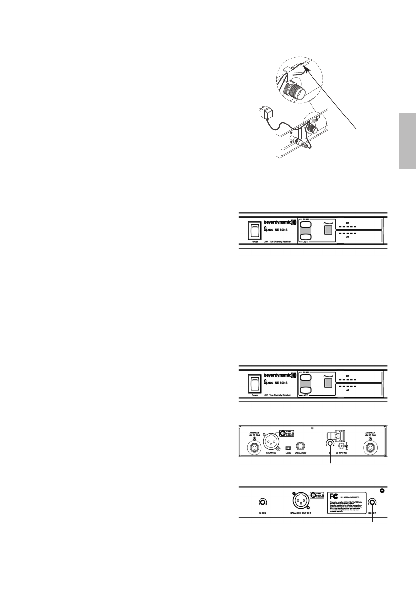
On-off switch with LED indicator
Scan button
Channel indicator
RF level indicator
AF level indicator
ACT button
19" rack mounting bracket (optional accessory)
NE 600 S only: with holes to mount the antennae on the front
Sticker indicating the frequency range
Front view – NE 600 S
Front view – NE 600 D
Page 8
Opus 600 – NE 600 Receiver
39
english
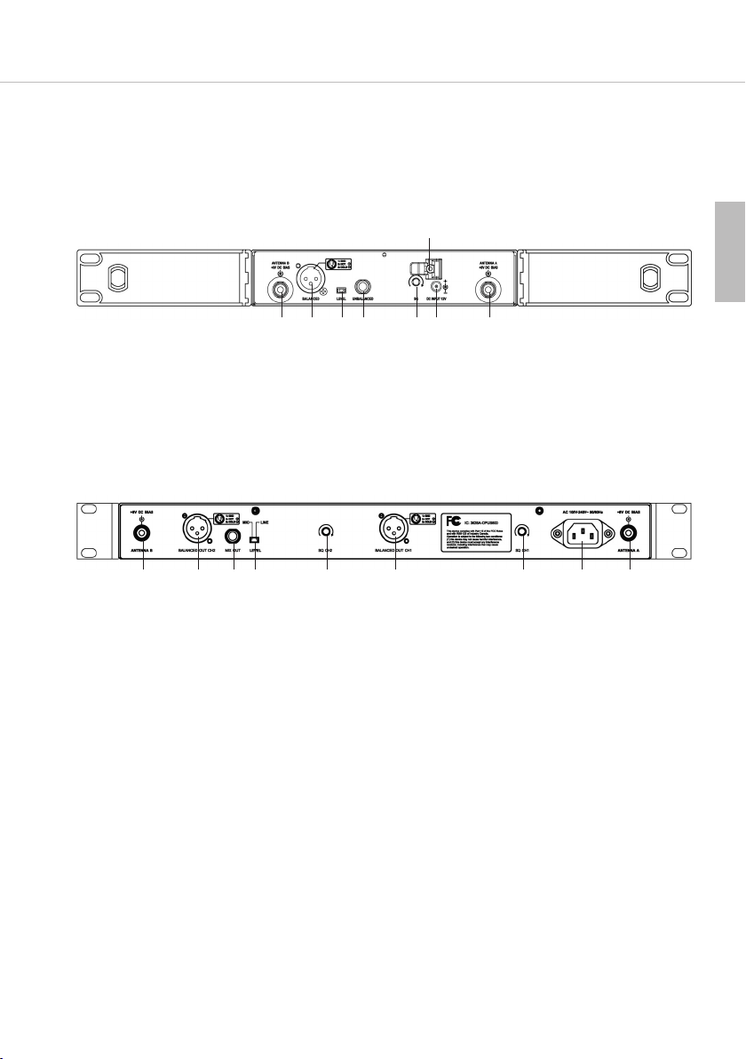
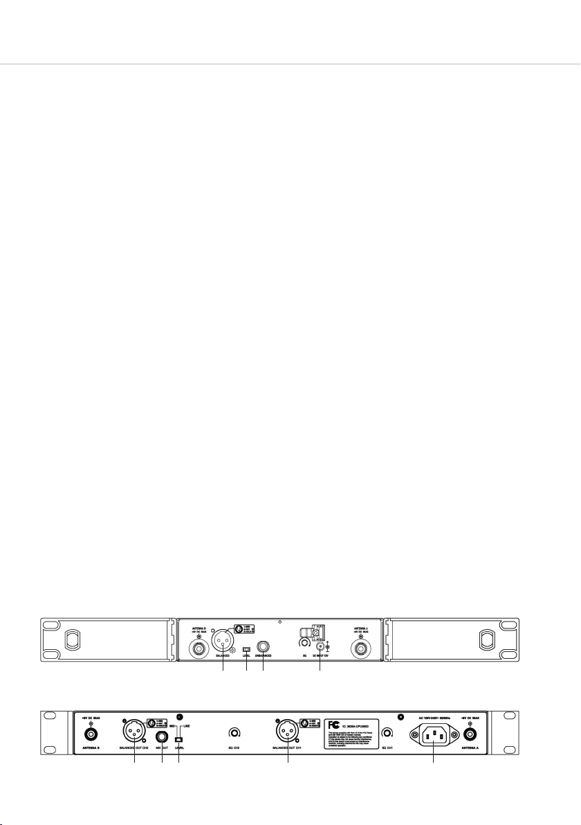
Rear view – NE 600 S
Rear view – NE 600 D
Antenna input B. TNC socket. With power supply for antenna amplifier.
Audio output, 3-pin XLR, balanced
Mic/Line level switch for audio output and . “Mic” for microphone level,
“Line” for Line out level
Audio output, 1/4" jack (6.35 mm), unbalanced
Variable squelch control
NE 600 S: DC connection for power supply unit, 12 V DC
NE 600 D: Power connection, 85 - 265 volts AC
Antenna input A. TNC socket. With power supply for antenna amplifier.
Cable holder for strain relief of the power cable
Page 9
Opus 600 – NE 600 Receiver
40
2.2 How to connect the antennae
Connect the antennae to the TNC sockets and and set them at an angle (60°).
Please note that for diversity operation both antennae have to be connected. A weighting circuit silently
switches the signal with the better S/N ratio to the output.
Important:
Avoid obstacles between antennae and transmitter; otherwise the reception could be disturbed.
2.3 Where to place the receiver
• Place the diversity receiver in the same room or area as the transmitters. Make sure the diversity
receiver is placed as close as possible to the transmitter.
• Ensure that the NE 600 is installed as close as possible to the mixing console or amplifier so that the
display can be seen at all times.
• Do not place the diversity receiver near digitally controlled equipment.
2.4 Connections
• Connect the Audio output to the corresponding input of the mixing console or amplifier. Use the
balanced Audio output , when you connect the receiver to a mixer/amplifier with a balanced
input.
• Use the unbalanced Audio output , when you connect the receiver to the “LINE” input of an
instrument amplifier.
• Make sure the Mic/Line level switch is switched to the correct position.
Switch to “LINE”, when you connect the receiver to a mixer/amplifier. When connecting to a
guitar amplifier you should choose “LINE”, or the volume may be too low.
Switch to “MIC-IN”, when you connect the receiver to a microphone input.
Incorrect positioning of the Mic/Line level switch can cause distortion.
• Make sure the mains voltage shown on the power supply unit corresponds to the local mains
voltage.
• Connect the power supply unit to the receiver or the power cable to the power connection
and to AC mains power.
NE 600 S
NE 600 D
Page 10
Opus 600 – NE 600 Receiver
41
english
Cable grip
• Thread the power cable through the cable grip
as shown on the illustration. The cable grip
prevents the connector from being pulled off
by accident.
2.5 How to operate the receiver
• Switch on the receiver . The red LED will
illuminate.
• As soon as you switch on the transmitter, the
RF indicator will illuminate. When you speak
into the microphone, the AF indicator will
illuminate according to the strength of the
sound level. If the LED does not illuminate or
there is no sound, the system should be
rechecked.
• The microphone output level has to be
adjusted at the amplifier or mixer.
2.6 How to adjust the squelch
• Due to the Pilotone and NoiseLock features
static noise should not occur.
• If the RF indicator illuminates before the
transmitter is switched on, noise will occur. The
more LEDs illuminate, the stronger the interference.
• In this case the inteference can be suppressed
with the squelch control by rotating it clockwise to the right.
• Please note, adjusting the squelch can affect
the sensitivity of the receiver and the distance
between transmitter and receiver antenna may
need to be reduced.
• If the interferences cannot be suppressed
with the squelch control, you should select a
different frequency (refer also to chapter
2.7 Channel / frequency selection).
NE 600 S / D
NE 600 S / D
NE 600 S
NE 600 D
Page 11

Opus 600 – NE 600 Receiver
42
2.7 Channel / frequency selection
• The NE 600 provides 16 adjustable frequencies.
• If you want to change the selected frequency, press the
Scan button until the channel indicator will flash.
Press the “Scan” button once again so that the receiver
will search for an interference-free frequency automatically.
• The frequency will be displayed as number or letter .
2.8 How to transmit the frequency
to the transmitter / ACT function
• Using the “ACT” button the frequency of the receiver
will be transmitted to the transmitter.
• Press the “ACT” button and hold the switched on
transmitter with the “ACT” mark or infra red point in front
of the infrared diode between the “ACT” and “Scan”
button.
• As soon as the frequency has been transmitted to the
transmitter, the “ACT” function will be finished automatically.
2.9 How to install the reciever into a 19" rack
NE 600 S one channel receiver
• To install the receiver into a 19" rack mount the optional FB 71 mounting bracket to the right and
left hand side of the receiver.
• If you would like to install two NE 600 S receivers into a 19" rack, mount connecting plates
between the top and bottom of the two receivers and the FB 72 mounting bracket to the right and
left hand side of the receiver.
NE 600 D dual channel receiver
• To install the receiver into a 19" rack mount the optional FB 72 mounting bracket to the right and
left hand side of the receiver.
NE 600 S / D
NE 600 S / D
FB 71
FB 72 FB 72
FB 71
Page 12

Opus 600 – NE 600 Receiver
43
english
2.10 How to connect and position remote antennae
In multichannel systems we recommend the use of the AT 70 A/B UHF antenna set consisting of antennae,
cables, antenna boosters and mounting kit.
1. Connect the receiving antennae to the corresponding antenna inputs and place the antennae to the
right and left of the receiver. Diversity reception is improved when the antennae are vertical or slightly
tilted.
2. The distance between the two receiving antennae should be at least 1 m.
> 1 m
> 3 m
> 1 m
AB
Stage
Auditorium
3. The distance between transmitting and receiving antennae should be at least 3 m to avoid
overloading and interference between different channels. We therefore recommend installing the
antennae in a high position, especially in multi-channel systems.
4. If the operating range of the transmitters is
greater than the stage, the antennae can be
mounted vertically on the ceiling. The distance
between the two receiving antennae should
be approximately half the total operating
range.
Please note:
1. Install the receiving antennae in the same area as the transmitter.
2. To avoid interference do not install the antennae near digitally controlled components.
3. Keep a minimum distance of 0.5 m from metallic objects, including reinforced concrete walls or
pillars.
4. Do not bend the antenna cables at the antenna input, and ensure that they are not subjected to
undue stress.
Operating range of the transmitter
Stage
Page 13

Opus 600 – ZAS 800 Antenna Splitter
44
2.11 ZAS 800 antenna splitter
2.11.1 Controls and indicators
On-off switch and power on LED. When the antenna splitter is switched on, the red LED will illuminate.
Outputs to connect the receivers
DC-connection to connect the DC power supply unit (12 V)
Antenna sockets A/B. DC-Out: 8 V / 170 mA
Mounting brackets for 19" rack mounting
2.11.2 Installation
Page 14

Opus 600 – ZAS 800 Antenna Splitter
45
english
1. Mount the ZAS 800 antenna splitter and the NE 600 receivers into a 19" rack by using the
mounting brackets.
2. Connect the supplied antennae to the antenna sockets A/B . You can also use optional remote
antennae. For mounting the antennae on the front use the optional FB 30 mounting bracket.
3. Connect the NE 600 receivers to the ZAS 800 antenna splitter with the supplied cables.
4. Connect the power supply unit to the DC-connection and to AC power. (Caution: Make sure that
the indicated voltage corresponds to the local voltage.)
5. Switch on the ZAS 800 antenna splitter .
2.11.3 General information
1. The antenna sockets have a voltage of 8 V DC. To avoid a short circuit the sockets must not touch
the rack housing.
2. For the connection of remote antennae use usual 50Ω coaxial cables. The longer the cable, the
higher the RF signal loss. Therefore, the cable length should not exceed 6 m.
The larger the diameter of cable, the lower the signal loss. If you need cables longer than 6 m you
should therefore use cables with a larger diameter to reduce the loss of signal.
3. Use 50Ω coaxial cables to connect the NE 600 receivers to the ZAS 800 antenna splitter. The
distance between these devices should be as short as possible. We recommend using the supplied
cables.
4. Supplied accessories:
8 x RG 58 AU cables, 40 cm (TNC)
1 pair FB 30 rack mount brackets (incl. front mounting option)
1 x power supply unit
Page 15

Opus 600 – S 600 Handheld Transmitter
46
3. S 600 handheld transmitter
3.1 Controls and indicators
There are different condenser and dynamic microphone capsules for the handheld transmitter (refer to
chapter 10. Optional accessories).
Microphone capsule (can be unscrewed)
Battery status indicator
On-off switch
Infrared diode (at the bottom of the transmitter)
3.2 How to insert the batteries /
rechargeable batteries
1. Unscrew the battery cap counter-clockwise.
2. Insert two 1.5 V batteries (AA) or fully charged
NiMH batteries into the battery compartment
observing the polarity markings.
3. The battery status indicator should flash for a
moment. If the battery status indicator does not
flash, the battery is not inserted correctly or empty.
Insert the battery correctly or replace it.
S 600
Page 16

Opus 600 – S 600 Handheld Transmitter
47
english
3.3 How to operate the handheld transmitter
1. When the microphone is switched on, the battery status indicator will flash for a moment.
2. As soon as an audio signal is transmitted, the AF meter on the receiver will display a signal.
3. When you do not use the microphone, make sure it is switched off. If you do not use the microphone
for several weeks or months, please remove the battery as it can leak after some time and damage
parts of the transmitter.
4. The battery status indicator will not illuminate, when the frequency is transmitted via the ACT
function to the transmitter. If the battery status indicator will flash, transmitter and receiver do
not operate with the same frequency. Make sure that transmitter and receiver operate with the
same frequency (refer to type plate).
3.4 How to change the microphone capsule
There are different microphone capsules available for the handheld transmitter. If you want to change
the microphone capsule, turn it anti-clockwise to unscrew it from the transmitter. Put the selected
microphone capsule onto the transmitter and turn it clockwise to tighten.
DM 960
Hypercardioid dynamic microphone capsule. Suitable for vocals and broadcasting applications. Weight 191 g.
DM 969
Supercardioid dynamic microphone capsule. Suitable for vocals.
Weight 131 g.
EM 981
Cardioid electret condenser microphone capsule for solo vocals, conferences
and speech. Weight 191 g.
Page 17
Opus 600 – S 600 Handheld Transmitter
48
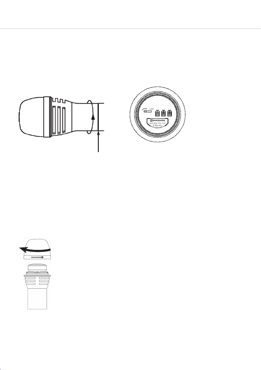
3.5 How to set the low-cut filter
• The EM 981 microphone capsule features a low-cut filter to compensate the close-miking effect which
ususally occurs with directional microphones. To set the low-cut filter unscrew the complete
microphone head with the upper shaft as indicated by the arrows.
• At the bottom of the microphone head you can set the low-cut filter.
• Standard setting: linear (position Lin)
Unscrew microphone head Set low-cut filter
3.6 Maintenance
• Protect the handheld transmitter from humidity, knocks and shock. Avoid dropping the transmitter at
all times.
• For cleaning metal surfaces, use a soft cloth moistened with methylated spirits or alcohol.
• As soon as your microphone sounds dull, you should clean the integrated pop shield. Proceed as
described in the following.
DM 960
• Unscrew the upper part of the microphone basket (turn anti-clockwise).
• Clean it under clear water.
• Let the pop shield dry overnight before you replace it.
• The upper part of the microphone basket cannot be cleaned in a dishwasher.
Page 18

Opus 600 – S 600 Handheld Transmitter
49
english
EM 981
• Unscrew the microphone capsule (turn anti-clockwise).
• Unscrew the wire mesh pop shield (turn anti-clockwise).
• Clean the pop shield under clear running water.
• Allow the pop shield to dry overnight before you replace it.
• The wire mesh pop shield cannot be cleaned in a dishwasher.
DM 969
• Unscrew the upper part of the microphone basket (turn anti-clockwise).
• Pull out the foam pop shield and clean it under clear running water.
• If necessary, use a mild washing-up liquid.
• Dry it afterwards with a hairdryer or allow it to dry overnight.
• Place the dry pop shield inside the microphone basket and replace the
microphone basket by screwing it on clockwise.
Page 19

Opus 600 – TS 600 Beltpack Transmitter
50
4. TS 600 beltpack transmitter
4.1 Controls and indicators
Transmitting antenna
Battery status LED to indicate the power on-off and battery status.
(a) When the beltpack transmitter is switched on this LED will flash for a moment to indicate the
normal battery status.
(b) When the LED stays red after having switched on the transmitter the battery is too weak and
must be replaced.
On-off switch (ON = switch to “ON“-position; OFF = switch to “OFF“-position).
Switch off the transmitter when not in use.
AF input, 4-pin mini XLR for microphones (lavalier, neckworn mics).
For connection please refer to chapter 4.5 AF Connection.
Infrared receiving diode for ACT function
Gain control to adjust input gain.
Page 20

Opus 600 – TS 600 Beltpack Transmitter
51
english
GT/MT switch: When you use electric guitars this switch must be in the “GT“ position. In the
GT mode the gain control is deactivated. Switch to the “MT“ position when you use condenser and
wired microphones. In the MT mode the gain control is activated.
Battery compartment and cover for two 1.5 V batteries (AA) or rechargeable NiMH batteries.
Removable belt clip. To remove use a screwdriver at a 45° angle.
This is how to remove the belt clip
4.2 How to insert the batteries / rechargeable batteries
1. Push down the two snap locks on the right and left of the battery compartment and open it.
Remove the batteries. Refer to Fig. 1.
2. Insert two 1.5 V batteries (AA) or rechargeable NiMH batteries into the battery compartment
observing the polarity markings. Refer to Fig. 2. Then close the battery compartment again.
Fig. 1 Fig. 2
Page 21

Opus 600 – TS 600 Beltpack Transmitter
52
4.3 How to operate the beltpack transmitter
1. Push down the two snap locks on the right and left of the battery compartment and open it. Now
you can adjust the GT/MT switch and the gain control .
2. Make sure that the transmitter and receiver are on the same frequency.
3. The battery status LED will flash for a moment when the transmitter is switched on and
indicates the normal battery status. When the LED fails to flash, there is no battery inserted, the
battery is leaking or inserted incorrectly.
4. Connect the microphone or instrument to the input socket and fasten the plug by turning clockwise. Refer to illustration below.
Important:
The LED does not illuminate when the frequency is transmitted to the transmitter via ACT function. If
the LED illuminates, however, the frequency bands of transmitter and receiver do not correspond to
each other. Please check, if transmitter and receiver work in the same frequency band (see type plate).
4.4 Adjusting the input gain
1. Switch on the TS 600 beltpack transmitter with the on-off switch . Turn the gain control fully
anti-clockwise to minimum gain.
2. Speak into the microphone at the maximum level you expect to use. We recommend you use the
letter “U” as a spoken “U” has a relatively good sine wave shape. Adjust the gain control to
the desired gain. On the NE 600 receiver the AF level must not show any clipping. When miking
instruments, play at the maximum level you expect to use.
Page 22

Opus 600 – TS 600 Beltpack Transmitter
53
english
4.5 AF connection
(1) 2-wire electret condenser microphone capsule
(2) 3-wire electret condenser microphone capsule
(3) Dynamic microphone
(4) Electric guitar
(5) Line-in (impedance 8Ω, attenuation 10 dB)
e.g. Opus 54.18,
Opus 55.18 Mk II
e.g. MCE 5.18,
MCE 10.18,
MCE 60.18
Page 23

Opus 600 – General Instructions
54
5. General instructions for all transmitters
5.1 Battery change
• Switch the transmitter off before changing the battery.
• If you do not use the transmitter for several weeks or months, please remove the battery as it can
leak after some time and damage parts of the transmitter. Even “leak proof” may leak after some
time. Damage caused by leaking batteries is not covered under warranty.
• Clean the battery contacts from time to time.
• Please do not throw used battery packs away with your household rubbish, but take them to your
local collection points.
• When using rechargeable batteries use conventional chargers.
5.2 Before the soundcheck
1. Check the transmitter battery and replace or recharge it if necessary. Use fresh alkaline batteries
only.
2. When the transmitter is switched off and immediately switched on again, it is possible that the
transmitter remains switched off. The cause is the function that allows to switch the transmitter
on / off silently. Should this problem occur during operation, the battery might have contact problems.
After switching off the transmitter you should wait at least 1 second, until you switch the transmitter
on again.
3. Check the performance area for dropouts. If you find any dropouts, try to eliminate them by
repositioning the antennae or the receiver.
4. The receiving antennae should be placed so that the distance between receiving antennae and
transmitter is at least 3 m. If necessary, use remote antennae (AT 707 A/B).
5. To avoid popping try holding the microphone at a slight angle below the mouth.
5.3 Positioning of transmitters if interference occurs
Put all transmitters in their position and switch them on. Switch each transmitter off one at a time and
check the receiver for interference in the corresponding channel.
The interference is possibly eliminated by changing the squelch (refer also to chapter 2.6 How to adjust
the squelch).
When using multi-channel-systems, please contact beyerdynamic. Interferences can also be caused by
DVB-T / DVB-H signals or signals of other applications in the UHF range in the neighbourhood.
5.4 What to do to avoid feedback
Feedback is caused by your microphone getting too close to a loudspeaker.
We recommend:
• Move away from the loudspeaker.
• Turn the microphone away from the loudspeaker.
Page 24

Opus 600 – Trouble Shooting
55
english
6. Trouble shooting
6.1 NE 600 diversity receiver
Problem Possible Cause Solution
No function •
Power supply is interrupted,
receiver is not connected to
the mains
• Connect the receiver to
AC power
No reception • Transmitter is not switched
on
• Transmitter works on a
different frequency
• Defect in the antenna cables
with remote antennae
• Switch on the transmitter
• Adjust the correct frequency
with the ACT function
• Check the antenna cables
Distorted sound • Input amplifier of the
connected mixer is
overloaded
• Use the gain control of the
mixer or adjust the volume
No sound, RF indication is okay,
AF indication is missing during
modulation
• Wrong indication caused by
strong interference signals
• No microphone connected to
TS 600 beltpack transmitter
• Select another frequency
• Connect a suitable
microphone
6.2 Handheld and beltpack transmitter
Problem Possible Cause Solution
No function • Transmitter and receiver have
different frequencies
• Insufficient battery voltage
• Poor battery contact,
batteries inserted incorrectly
• Check if transmitter and
receiver have the same
frequency
• Replace the batteries or
recharge them, if you use
rechargeable batteries
• Check the batteries and
insert them again
No RF indication at the receiver • Transmission distance
between transmitter and
receiver is too great
• Reduce the distance between
transmitter and receiver
Noise/chirping • Interference from other
transmitters
• Two transmitters are on the
same frequency
• Battery of the transmitter is
too weak
• Switch off the other
transmitters
• Change the frequency of one
transmitter
• Replace the batteries or
recharge them
Page 25

Opus 600 – Licensing
56
7. Maintenance
In the unlikely event of equipment failure, the product should be returned to your beyerdynamic dealer.
Unauthorised attempts at repair may invalidate the warranty.
8. Licensing
In most countries around the world, wireless systems must be approved for use by the authorities and
it may be necessary to obtain a licence to use it legally. Your local beyerdynamic dealer will be able to
give you details on wireless system regulations for your area.
The components of the Opus 600 system are approved according to the directive R&TTE 99/5/EEC:
TS 600
SDM 660, SDM 669, SEM 681
under the CE 0682 ! identification
9. Components
The following components are available as sets or individual components in the frequency range
506 - 530 MHz, 668 - 692 MHz, 774 - 798 MHz, 790 - 814 MHz or 841 - 865 MHz:
NE 600 S UHF true diversity receiver, one channel, 9.5" metal housing,
1 HU, PLL synthesizer, Pilotone, LED indicators, ACT and SCAN functions,
16 pre-programmed frequencies, incl. mounting brackets,
external power supply unit
NE 600 D UHF true diversity receiver, dual channel, 9.5"metal housing,
1 HU, PLL synthesizer, Pilotone, LED indicators, ACT and SCAN functions,
16 pre-programmed frequencies, incl. mounting brackets, and
cables to mount the antennae on the front
S 600 UHF handheld transmitter, without microphone capsule, plastic housing,
battery low LED, ACT function, incl. 2 x AA batteries
TS 600 UHF beltpack transmitter, without microphone, plastic housing,
battery low LED, ACT funktion, incl. 2 x AA batteries
Page 26

Opus 600 – Optional Accessories
57
english
10. Optional accessories
NE 600 diversity receiver
Antenna splitter
ZAS 800 Antenna splitter, active, 19" housing,
incl. connecting cables, 506 - 530 MHz. . . . . . . . . . . . . . . . . . . Order # 497.045
ZAS 800 same as above, but 668 - 692 MHz. . . . . . . . . . . . . . . . . . . . . . Order # 491.551
ZAS 800 same as above, but 774 - 798 MHz. . . . . . . . . . . . . . . . . . . . . . Order # 473.081
ZAS 800 same as above, but 790 - 814 MHz. . . . . . . . . . . . . . . . . . . . . . Order # 491.667
ZAS 800 same as above, but 841 - 865 MHz. . . . . . . . . . . . . . . . . . . . . . Order # 491.675
Antennae
AT 70 A/B Set UHF antenna set for NE 600,
incl. 2 x AT 70 B TNC booster,
2 x AT 70 TNC antenna and
2 x MS 10 mounting kit. . . . . . . . . . . . . . . . . . . . . . . . . . . . . . . Order # 459.976
FBC 71 Cable rear-to-front for NE 600 and ZAS 800 . . . . . . . . . . . . . . . Order # 469.823
FB 71 Mounting bracket, metal, for mounting
one NE 600 S receiver into a 19" rack, 1 HU . . . . . . . . . . . . . . . Order # 469.793
FB 72 Mounting bracket, metal, for mounting
two NE 600 S receivers or one NE 600 D receiver
into a 19" rack, 1 HU . . . . . . . . . . . . . . . . . . . . . . . . . . . . . . . . Order # 469.807
S 600 handheld transmitter
Microphone capsules
DM 960 B Dynamic, hypercardioid, black . . . . . . . . . . . . . . . . . . . . . . . . Order # 490.490
DM 960 S Dynamic, hypercardioid, silver. . . . . . . . . . . . . . . . . . . . . . . . . Order # 490.504
DM 969 S Dynamic, supercardioid, silver . . . . . . . . . . . . . . . . . . . . . . . . . Order # 490.512
EM 981 S Electret condenser, cardioid, silver. . . . . . . . . . . . . . . . . . . . . . Order # 490.520
TS 600 beltpack transmitter
Microphones
MCE 5.18 Condenser clip-on microphone, omnidirectional, black . . . . . . Order # 471.879
MCE 10.18 Condenser clip-on microphone, cardioid, black. . . . . . . . . . . . Order # 471.895
MCE 60.18 Condenser clip-on microphone, omnidirectional, black . . . . . . Order # 469.548
Opus 54.18 BLK Neckworn microphone, condenser, cardioid, black . . . . . . . . . Order # 464.945
Opus 54.18 SC Neckworn microphone, condenser, cardioid, beige . . . . . . . . . Order # 474.223
Opus 55.18 MkII BLK Neckworn microphone, condenser, omnidirectional, black . . . Order # 475.394
Opus 55.18 MkII SC Neckworn microphone, condenser, omnidirectional, beige . . . Order # 475.386
TG-X 54.18 BLK Neckworn microphone, condenser, cardioid, black . . . . . . . . . Order # 700.061
TG-X 54.18 SC Neckworn microphone, condenser, cardioid, beige . . . . . . . . . Order # 700.053
TG-X 55.18 BLK Neckworn microphone, condenser, omnidirectional, black . . . Order # 700.069
TG-X 55.18 SC Neckworn microphone, condenser, omnidirectional, beige . . . Order # 700.088
Cable
MJ 41 G Instrument cable, 1/4" jack (6.35 mm) for TS 600. . . . . . . . . . Order # 460.087
Page 27

Opus 600 – Technical Specifications
58
11. Technical specifications
NE 600 diversity receiver
Operating principle . . . . . . . . . . . . . . . . . True diversity receiver (UHF)
Frequency range . . . . . . . . . . . . . . . . . . . 506 - 530 MHz
668 - 692 MHz
774 - 798 MHz
790 - 814 MHz*
841 - 865 MHz*
Power consumption . . . . . . . . . . . . . . . . NE 600 S: 7 W
NE 600 D: 13 W
Power consumption
in stand-by mode . . . . . . . . . . . . . . . . . . NE 600 S: 1.5 W
NE 600 D: 2.5 W
Switching bandwidth . . . . . . . . . . . . . . . 24 MHz
Sensitivity . . . . . . . . . . . . . . . . . . . . . . . . 2 µV
Antenna connection . . . . . . . . . . . . . . . . 2 x TNC
Nominal deviation. . . . . . . . . . . . . . . . . . ± 40 kHz
Output level . . . . . . . . . . . . . . . . . . . . . .
1.2 V
Compander system. . . . . . . . . . . . . . . . . . NE572
Signal-to-noise ratio . . . . . . . . . . . . . . . . > 110 dB(A)
T.H.D. . . . . . . . . . . . . . . . . . . . . . . . . . . . < 0.5% at 1 kHz
Squelch . . . . . . . . . . . . . . . . . . . . . . . . . 2 µV - 1 mV, adjustable
Power supply . . . . . . . . . . . . . . . . . . . . . 12 V - 15 V DC
Mains . . . . . . . . . . . . . . . . . . . . . . . . . . . 110 V - 240 V AC
Dimensions. . . . . . . . . . . . . . . . . . . . . . . NE 600 S (L x B x H) 210 x 235 x 43 mm
NE 600 D (L x B x H) 420 x 204 x 44 mm
Weight . . . . . . . . . . . . . . . . . . . . . . . . . . NE 600 S 1.1 kg (without power supply unit)
NE 600 D 2.2 kg
Minimum distance of the profiles
when mounting into a 19" rack . . . . . . . 446 mm
SDM 660 / SDM 669 / SEM 681 handheld transmitter
Polar pattern. . . . . . . . . . . . . . . . . . . . . . Hypercardioid (SDM 660)
Supercardioid (SDM 669)
Cardioid (SEM 681)
Transducer type . . . . . . . . . . . . . . . . . . . Dynamic (SDM 660, SDM 669)
Electret condenser (SEM 681)
Frequency range . . . . . . . . . . . . . . . . . . . 506 - 530 MHz
668 - 692 MHz
774 - 798 MHz
790 - 814 MHz*
841 - 865 MHz*
Modulation. . . . . . . . . . . . . . . . . . . . . . . FM
Nominal deviation. . . . . . . . . . . . . . . . . . ± 40 kHz
Radiated transmitter power . . . . . . . . . . 10 mW
Compander system. . . . . . . . . . . . . . . . . NE572
*NOT for use in the USA or Canada
Page 28

Opus 600 – Technical Specifications
59
english
Max. SPL. . . . . . . . . . . . . . . . . . . . . . . . . 146 dB
AF transmission range
SDM 660 . . . . . . . . . . . . . . . . . . . . . . . . 55 - 18,000 Hz (close miking 2 cm) at 80 dB SPL
SDM 669 65 - 16,000 Hz (close miking 2 cm) at 80 dB SPL
SEM 681 50 - 18,000 Hz (close miking 2 cm) at 80 dB SPL
Rear attenuation. . . . . . . . . . . . . . . . . . . -20 dB at 1 kHz / 120° (SDM 660)
-15 dB at 1 kHz / 145° (SDM 669)
-15 dB at 1 kHz / 180° (SEM 681)
Signal-to-noise ratio . . . . . . . . . . . . . . . . > 110 dB
T.H.D. . . . . . . . . . . . . . . . . . . . . . . . . . . . < 0.5% at 1 kHz
Transmission range . . . . . . . . . . . . . . . . . 100 m
Power supply . . . . . . . . . . . . . . . . . . . . . 2 x 1.5 V batteries (AA)
Current consumption . . . . . . . . . . . . . . . approx. 85 mA
Operating time . . . . . . . . . . . . . . . . . . . . > 20 hours with alkaline batteries
Dimensions
Length S 600 . . . . . . . . . . . . . . . . . . . . . . . . 188 mm
Shaftø S 600. . . . . . . . . . . . . . . . . . . . . . 38 mm
Weight with batteries . . . . . . . . . . . . . . . 163 g
TS 600 beltpack transmitter
Frequency range . . . . . . . . . . . . . . . . . . . 506 - 530 MHz
668 - 692 MHz
774 - 798 MHz
790 - 814 MHz*
841 - 865 MHz*
Modulation. . . . . . . . . . . . . . . . . . . . . . . FM
Nominal deviation. . . . . . . . . . . . . . . . . . ± 40 kHz
Radiated transmitter power . . . . . . . . . . 20 mW
Compander system. . . . . . . . . . . . . . . . . NE572
Signal-to-noise ratio . . . . . . . . . . . . . . . . > 110 dB
T.H.D. . . . . . . . . . . . . . . . . . . . . . . . . . . . < 0.5% at 1 kHz
Frequency response . . . . . . . . . . . . . . . . 50 Hz - 18,000 Hz
Gain . . . . . . . . . . . . . . . . . . . . . . . . . . . . 10 mV - 0.3 V adjustable, at nominal deviation
Power supply . . . . . . . . . . . . . . . . . . . . . 2 x 1.5 V batteries (AA)
Current consumption . . . . . . . . . . . . . . . approx. 85 mA
Operating time . . . . . . . . . . . . . . . . . . . . > 20 hours with alkaline batteries
Dimensions (L x W x D) . . . . . . . . . . . . . . 110 x 63 x 21.5 mm
Weight with batteries . . . . . . . . . . . . . . . 145 g
4-pin connection . . . . . . . . . . . . . . . . . . Pin 1 = Ground, Pin 2 = IN1, Pin 3 = IN2,
Pin 4 = +5 V; refer also to chapter 4.5 AF connection
*NOT for use in the USA or Canada
Page 29

Opus 600 – Technical Specifications
60
ZAS 800 antenna splitter
Inputs . . . . . . . . . . . . . . . . . . . . . . . . . . . 2 x 50 Ω (TNC)
Outputs . . . . . . . . . . . . . . . . . . . . . . . . . 8 x 50 Ω (TNC)
Frequeny range. . . . . . . . . . . . . . . . . . . . depending on the version
Amplification . . . . . . . . . . . . . . . . . . . . . 0 dB ±3 dB
Decoupling attenuation . . . . . . . . . . . . . > 15 dB
Power supply . . . . . . . . . . . . . . . . . . . . . 12 V - 15 V DC, 1A current min.
Mains . . . . . . . . . . . . . . . . . . . . . . . . . . . 110 - 240 V AC
Current consumption . . . . . . . . . . . . . . . approx. 170 mA
Dimensions (L x W x H) . . . . . . . . . . . . . . 482 x 190 x 44 mm
Weight . . . . . . . . . . . . . . . . . . . . . . . . . . approx. 1547 g
Page 30

Opus 600 – Notes
61
english
 Loading...