

Beyerdynamic QUINTA TH, QUINTA CU, Quinta MU 23, Quinta MU 22, QUINTA RS Quick Start Manual
...
QUINTA
DIGIT
ALES DRAH
TLOSES KON
FEREN
ZSYSTEM
DIGITAL WIRELESS CON
FEREN
CE SYSTEM
SYSTÈME N
U
MÉRIQU
E SAN
S FIL DE CON
FEREN
CE
Guide de démarrage rapide
Quick Start Guide
Kurzanleitung

Registrierung
Bitte registrieren Sie sich unter www.beyerdynamic.com/quinta/register. Wir werden Sie über Software-Updates und Neuheiten rund um unsere Quinta-Produktfamilie informieren. Bei Registrierung
können Sie das Bedienmodul der Konferenzsoftware (Quinta Controller) gratis dazu erhalten.
Registration
Please register at www.beyerdynamic.com/quinta/register. We will inform you about software updates
and new developments of our Quinta product range. When registering you will be eligible to receive
the Conference software control module (Quinta Controller) free of charge.
Enregistrement
Veuillez vous enregistrer sur www.beyerdynamic.com/quinta/register. Nous vous ferons parvenir des
informations sur les mises à jour logicielles et nouveautés tout autour de notre gamme de produits
Quinta. En vous enregistrant, vous pouvez recevoir gratuitement le module de pilotage du logiciel de
conférence (Quinta Controller).

Quick Start Guide Quinta – Inhalt / Contents / Sommaire
3
deutsch
Quick Start Guide Quinta
deutsch
1. Einführung. . . . . . . . . . . . . . . . . . . . . . . . . . . . . . Seite 4
2
. Steuerzentrale Quinta CU und RS. . . . . . . . . . . . . . Seite 4
2.1 Bedien- und Kontrollelemente. . . . . . . . . . . . . Seite 4
2
.2 Inbetriebnahme. . . . . . . . . . . . . . . . . . . . . . . Seite 5
2.2.1 Steuerzentrale Quinta CU. . . . . . . . . . Seite 5
2.2.2 Steuerzentrale Quinta RS. . . . . . . . . . Seite 6
3. Sprechstellen Quinta MU. . . . . . . . . . . . . . . . . . . . Seite 8
3.1 Bedien- und Kontrollelemente. . . . . . . . . . . . . Seite 8
3.2 Inbetriebnahme . . . . . . . . . . . . . . . . . . . . . . Seite 11
4. Grenzflächenmikrofon Quinta TB. . . . . . . . . . . . . . . Seite 13
4.1 Bedien- und Kontrollelemente. . . . . . . . . . . . . Seite 13
4.2 Inbetriebnahme . . . . . . . . . . . . . . . . . . . . . . Seite 13
5. Handsender Quinta TH. . . . . . . . . . . . . . . . . . . . . . Seite 15
5.1 Bedien- und Kontrollelemente. . . . . . . . . . . . . Seite 15
5.2 Inbetriebnahme . . . . . . . . . . . . . . . . . . . . . . Seite 16
6. Entsorgung. . . . . . . . . . . . . . . . . . . . . . . . . . . . . . Seite 17
7. Konformitätserklärung. . . . . . . . . . . . . . . . . . . . . . Seite 17
Quick Start Guide Quinta
Quick Start Guide Quinta
englishfrançais
1. Introduction. . . . . . . . . . . . . . . . . . . . . . . . . . . . . Page 20
2. Quinta CU and RS Control Units. . . . . . . . . . . . . . . Page 20
2.1 Controls and Indicators. . . . . . . . . . . . . . . . . . Page 20
2.2 How to Operate the System. . . . . . . . . . . . . . . Page 21
2.2.1 Quinta CU Control Unit. . . . . . . . . . . Page 21
2.2.2 Quinta RS Control Unit. . . . . . . . . . . Page 22
3. Quinta MU Microphone Units. . . . . . . . . . . . . . . . . Page 24
3.1 Controls and Indicators. . . . . . . . . . . . . . . . . . Page 24
3.2 How to Operate the Microphone Units . . . . . . . Page 27
4. Quinta TB Boundary Microphone. . . . . . . . . . . . . . . Page 29
4.1 Controls and Indicators. . . . . . . . . . . . . . . . . . Page 29
4.2 How to Operate the Boundary Microphone . . . . Page 29
5. Quinta TH Handheld Transmitter. . . . . . . . . . . . . . . Page 31
5.1 Controls and Indicators. . . . . . . . . . . . . . . . . . Page 31
5.2 How to Operate the Handheld Transmitter . . . . Page 32
6. Disposal. . . . . . . . . . . . . . . . . . . . . . . . . . . . . . . . Page 34
7. EU Declaration of Conformity / FCC Regulation. . . . Page 34
1. Introduction. . . . . . . . . . . . . . . . . . . . . . . . . . . . . Page 36
2. Centrale de commande Quinta CU et RS. . . . . . . . . Page 36
2.1 Eléments de commande et de contrôle. . . . . . . Page 36
2.2 Mise en service. . . . . . . . . . . . . . . . . . . . . . . Page 37
2.2.1 Centrale de commande Quinta CU. . . . Page 37
2.2.2 Centrale de commande Quinta RS. . . . Page 38
3. Postes d’appel Quinta MU. . . . . . . . . . . . . . . . . . . Page 40
3.1 Eléments de commande et de contrôle. . . . . . . Page 40
3.2 Mise en marche . . . . . . . . . . . . . . . . . . . . . . Page 43
4. Microphone à effet de surface Quinta TB. . . . . . . . . Page 45
4.1 Eléments de commande et de contrôle. . . . . . . Page 45
4.2 Mise en service . . . . . . . . . . . . . . . . . . . . . . . Page 45
5. Emetteur portable Quinta TH. . . . . . . . . . . . . . . . . Page 47
5.1 Eléments de commande et de contrôle. . . . . . . Page 47
5.2 Mise en service . . . . . . . . . . . . . . . . . . . . . . . Page 48
6. Evacuation. . . . . . . . . . . . . . . . . . . . . . . . . . . . . . Page 50
7. Déclaration de conformité / FCC Régulation. . . . . . . Page 50/51
Quick Start Guide Quinta – Control Unit
20
1. Introduction
Thank you for selecting the digital wireless Quinta conference system. Please take some time to read
carefully through this manual before setting up the equipment.
Please refer also to the extensive “Quinta Conference System” manual and “Quinta Software” manual,
which you will find in the internet at www.beyerdynamic.com.
Please also refer to the supplied “Safety Information” booklet.
2. Quinta CU and RS Control Units
The Quinta RS and Quinta CU (from software version 3.0) control units can be operated in two
different modes, they can be selected via the Quinta Software. In the Conference mode all devices
(Quinta MU, Quinta TB, Quinta TH) have the functionality of a conference microphone unit, while in
the Microphone mode all devices have the functionality of a wireless microphone. For more information
please refer to the Quinta Software manual.
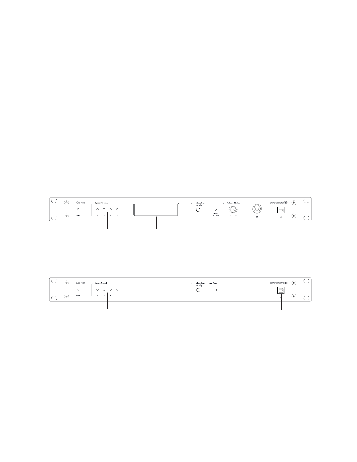
2.1 Controls and Indicators
Front View – Quinta CU
Power on LED
Audio channel LEDs 1 to 4 (white = channel vacant; red = channel occupied)
Display to indicate operating mode, channel, headphone volume
Standby button to turn off all microphone units and microphones centrally
Quinta CU: Push-button for frequency band selection
Quinta RS: Push-button to clear all microphones
Volume control for headphone / channel
Headphone connection
USB connection
Front View – Quinta RS
Quick Start Guide Quinta – Control Unit
21
english
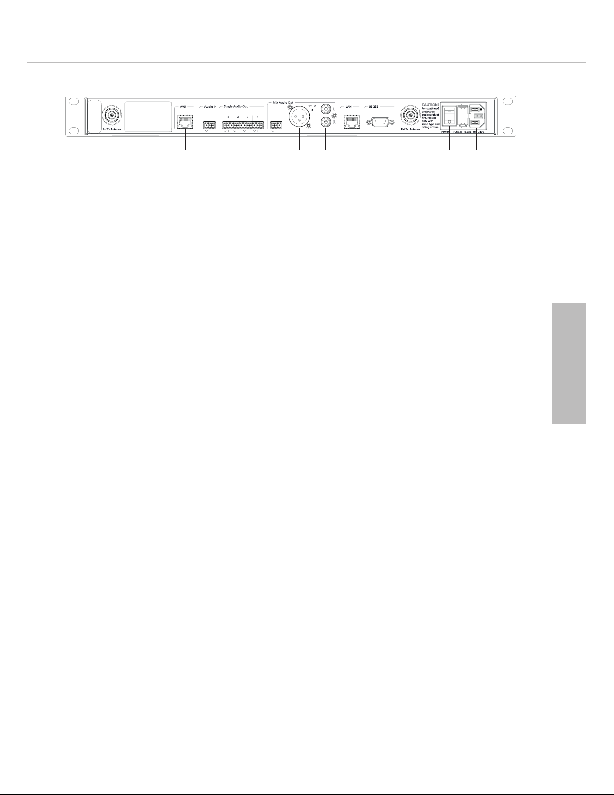
Rear View – Quinta CU and RS
Antenna connections
AVB (Audio Video Bridging) network connection for digital audio signals via CAT5 cables, RJ45
Audio input (Audio IN) for the connection of external sound sources, 3-pin Phoenix terminal strip,
balanced
Audio output, individual channels, 4 x 3-pin Phoenix terminal strips, balanced
Audio output Mix (Master), 3-pin Phoenix terminal strips, balanced
Audio output Mix (Master), 3-pin XLR, balanced
Audio output Mix (Master), RCA, unbalanced
LAN connection for PC / network, RJ 45
Connection for media control system / PC / network, RS 232
On/Off switch
Fuse
Mains connection
2.2. How to Operate the System
2.2.1 Quinta CU Control Unit
The Quinta CU control unit is the heart of the system. It is used to control the delegate and chairman
microphone units. With one control unit, a maximum of four people can speak simultaneously
(e.g. three delegates and one chairman). The radio transmission is in the triple-band operation
(2.4 / 5.2 / 5.8 GHz frequency band).
Delivery state: Conference mode
Where to place the control unit
• If you do not use remote antennae, place the Quinta CU control unit in the room where the
meeting takes place. If you use remote antennae, place the antennae in the conference room.
• Avoid shadowing effect of the antennae, especially by metallic surfaces.
• A free line of sight between the Quinta MU microphone units, Quinta TB boundary microphones and
Quinta TH handheld transmitter and the antennae of the Quinta CU control unit is essential for the
operation.
How to connect the antennae
• Connect the antennae to the antenna connections . Please note that for diversity operation both
antennae have to be connected! A weighting circuit is used to make sure that the better antenna
signal is received.
• For stand-alone operation we recommend using the supplied CA Q 11 angled rod antennae.
• The Quinta CU control unit can also be operated with remote antennae. We recommend extremely
low attenuation connecting cables which are 10 m [32.8 ft.] or 20 m [65.6 ft.] long. Please note
that the antennae have to be installed remotely.

Quick Start Guide Quinta – Control Unit
22
Connections
• If required, connect the Audio Mix , XLR or Cinch master output of the Quinta CU control
unit to the input of a mixing console or amplifier.
• Connect the Quinta CU control unit to the mains . The internal power supply unit of the control
unit can automatically adjust between 100 and 240 V at 50 - 60 Hz. Verify that the voltage rating
of the unit matches that of the AC mains outlet you are to use. If you connect the unit to the wrong
voltage, you may seriously damage it. Always route cables running to the unit where they will not
be pinched or cut by heavy or sharp objects.
• For using the AVB network connection, please refer to the extensive “Quinta Conference System”
manual.
How to operate the control unit
• Turn on the Quinta CU control unit with the On/Off switch . The Power on LED will illuminate.
The channel LED 1 to 4 will illuminate white to indicate the availability.
• Conference mode: As soon as a microphone is activated, the channel LED will illuminate red to
indicate that the channel is occupied.
• Microphone mode: As soon as there is an active radio connection between the microphone and
control unit (no matter if the microphone is open or muted) the appropriate channel display will
illuminate red to indicate that the channel is occupied. In the microphone mode a maximum of four
microphones can be operated with one control unit. If all four radio channels are occupied and
more microphones are activated, these microphones that are too many will automatically be
deactivated right away.
• At the factory the RF bands 2.4; 5.2 or 5.8 GHz* will be activated (Automatic Mode). This means
that the Quinta CU control unit will select a free frequency and if necessary it will select a different
free frequency without any interferences. This operating mode is recommended for normal use.
The free frequencies for the Quinta CU control unit can be deactivated via the Quinta software. The
devices (Quinta MU, Quinta TB and Quinta TH) will automatically be adjusted and without any
interruption to the frequency of the Quinta CU control unit. Please refer also to the “Quinta
Conference System” manual.
*Note:
The availability of the RF bands 2.4; 5.2 or 5.8 GHz depends on the selected region.
2.2.2 Quinta RS Control Unit
In conjunction with the Quinta TB boundary microphone the Quinta RS control unit is used for
video conferencing and/or small meetings. You can also use the Quinta RS control unit with the
Quinta MU microphone units or the Quinta TH handheld transmitter. With one Quinta RS control
unit you can operate a maximum of four microphones in the microphone mode.
The installation and operation is equal to the Quinta CU control unit. The Quinta RS control unit
has no display and can also be managed via the Quinta Software.
Delivery state: Microphone mode
Important: In the conference mode you can operate a maximum of 20 microphone units with the
Quinta RS. Furthermore, please note that the Quinta RS control unit does not provide any voting
function. Therefore, the Quinta RS control unit should not be used with the Quinta MU 23 V and
21 V microphone units if voting functions are required.
Where to place the control unit
• If you do not use remote antennae, place the Quinta CU control unit in the room where the
meeting takes place. If you use remote antennae, place the antennae in the conference room.
• Avoid shadowing effect of the antennae, especially by metallic surfaces.
 Loading...