

Page 1

BEDIENUNGSANLEITUNG
OPERATING INSTRUCTIONS
NOTICE D’UTILISATION
MANUAL DEL USUARIO
Opus 900
Drahtloses UHF-System
Wireless UHF System
Système sans fil UHF
Sistema inalámbrico en UHF
Page 2

3
INHALT / CONTENTS / SOMMAIRE
BEDIENUNGSANLEITUNG Opus 900
OPERATING INSTRUCTIONS Opus 900
NOTICE D’UTILISATION Opus 900
english deutschfrançais
Wichtige Sicherheitsinformationen . . . . . . . . . . . . Seite 6
Diversityempfänger NE 900 . . . . . . . . . . . . . . . . . . . Seite 8
Antennensplitter ZAS 800 . . . . . . . . . . . . . . . . . . . . Seite 16
Anschluss an einen PC . . . . . . . . . . . . . . . . . . . . . . . Seite 18
Handsender S 900 . . . . . . . . . . . . . . . . . . . . . . . . . . Seite 19
Taschensender TS 900 . . . . . . . . . . . . . . . . . . . . . . . Seite 25
Hinweise für alle Sender . . . . . . . . . . . . . . . . . . . . . Seite 31
Fehlercheckliste . . . . . . . . . . . . . . . . . . . . . . . . . . . . Seite 32
Service . . . . . . . . . . . . . . . . . . . . . . . . . . . . . . . . . . . . Seite 33
Zulassung und Anmeldepflicht . . . . . . . . . . . . . . . . Seite 33
Komponenten . . . . . . . . . . . . . . . . . . . . . . . . . . . . . Seite 34
Zubehör - optional . . . . . . . . . . . . . . . . . . . . . . . . . . Seite 35
Technische Daten . . . . . . . . . . . . . . . . . . . . . . . . . . . Seite 36
Konformitätserklärung . . . . . . . . . . . . . . . . . . . . . . Seite 140
Important Safety Information . . . . . . . . . . . . . . . . . Page 40
NE 900 Diversity Receiver . . . . . . . . . . . . . . . . . . . . Page 44
ZAS 800 Antenna Splitter . . . . . . . . . . . . . . . . . . . . Page 52
Connection to a PC . . . . . . . . . . . . . . . . . . . . . . . . . Page 54
S 900 Handheld Transmitters. . . . . . . . . . . . . . . . . . Page 55
TS 900 Beltpack Transmitter . . . . . . . . . . . . . . . . . . Page 61
General Instructions for all Transmitters . . . . . . . . Page 67
Trouble Shooting . . . . . . . . . . . . . . . . . . . . . . . . . . . Page 68
Maintenance. . . . . . . . . . . . . . . . . . . . . . . . . . . . . . . Page 69
Licensing . . . . . . . . . . . . . . . . . . . . . . . . . . . . . . . . . . Page 69
Components . . . . . . . . . . . . . . . . . . . . . . . . . . . . . . . Page 69
Optional Accessories . . . . . . . . . . . . . . . . . . . . . . . . Page 70
Technical Specifications . . . . . . . . . . . . . . . . . . . . . . Page 71
Declaration of Confirmity . . . . . . . . . . . . . . . . . . . . Page 140
Consignes de sécurité importants . . . . . . . . . . . . . . Page 74
Récepteur «Diversity» NE 900 . . . . . . . . . . . . . . . . . Page 76
Splitter d’antenne ZAS 800 . . . . . . . . . . . . . . . . . . . Page 84
Raccordement à un PC. . . . . . . . . . . . . . . . . . . . . . . Page 86
L’émetteur à main S 900 . . . . . . . . . . . . . . . . . . . . . Page 87
L’émetteur de poche TS 900 . . . . . . . . . . . . . . . . . . Page 93
Remarques concernant tout type d’émetteur. . . . . . Page 99
Dépannage . . . . . . . . . . . . . . . . . . . . . . . . . . . . . . . . Page 100
Service après-vente . . . . . . . . . . . . . . . . . . . . . . . . . Page 101
Homologation . . . . . . . . . . . . . . . . . . . . . . . . . . . . . Page 101
Eléments . . . . . . . . . . . . . . . . . . . . . . . . . . . . . . . . . . Page 102
Accessoires en option . . . . . . . . . . . . . . . . . . . . . . . Page 103
Spécifications techniques. . . . . . . . . . . . . . . . . . . . . Page 104
Déclaration de conformité . . . . . . . . . . . . . . . . . . . Page 140
Page 3

40
OPERATING INSTRUCTIONS OPUS 900
Thank you for selecting the Opus 900 wireless system. Please take some time to read
carefully through this manual before setting up the equipment.
Important:
• When you unpack the product, inspect it for transport damage. If you do find transport
damage, notify the transportation company without delay. Delay in reporting transport
damage could result in the loss of your rights to compensation.
Receiver
• READ these instructions.
• KEEP these instructions.
• HEED all warnings.
• Follow all instructions.
• Do not use this apparatus near water.
• Clean only with a dry cloth.
• Do not block any ventilation openings. Install in accordance with the manufacturer’s
instructions.
• Do not install near any heat sources such as radiators, heat registers, stoves or other
apparatus (including amplifiers) that produce heat.
• Do not defeat the safety purpose of the polarised or grounding-type plug. A polarised
plug has two blades with one wider than the other. A grounding type plug has two blades
and a third grounding prong. The wide blade or the third prong are provided for your
safety. If the provided plug does not fit into your outlet, consult an electrician for
replacement of the obsolete outlet.
• Protect the power cord from being walked on or pinched particularly at plugs,
convenience receptacles, and the point where they exit from the apparatus.
• Only use attachements/accessories specified by the manufacturer.
• Use only with the cart, stand, tripod, bracket or table specified by the manufacturer or
sold with the apparatus. When a cart is used, use caution when moving the cart/apparatus
combination to avoid injury from tip-over.
• Unplug this apparatus during lightning storms or when unused for long periods of time.
• Refer all servicing to qualified service personnel. Servicing is required when the apparatus
has been damaged in any way, such as power-supply cord or plug is damaged, liquid has
been spilled or objects have fallen into the apparatus, the
apparatus has been exposed to rain or moisture, does not operate normally, or has been
dropped.
• The equipment must be set up so that the mains switch, mains plug and all connection on
the rear of the device are easily accessible.
• The equipment must be connected to a mains socket that has an earth contact.
• Never expose the equipment to rain or a high level of humidity. For this reason do not
install it in the immediate vicinity of swimming pools, showers, damp basement rooms or
other areas with unusually high atmospheric humidity.
• Do not use the device/s outside. To reduce the risk of fire or electric shock, do not expose
this/these device/s to rain or
moisture.
• Never place objects containing liquid (e.g. vases or drinking glasses) on the equipment.
Liquids in the equipment could cause a short circuit.
Important Safety Instructions
Page 4

english
41
Transmitter
• Protect the transmitter from moisture and sudden impacts. You could either injure yourself
or others or damage the transmitter.
• Do not blow into the microphone. In a condenser microphone this could damage the
transformer. It is preferable to carry out a speech trial.
• Clip-on microphones are often very compact. If they are accidentally swallowed there is a
risk of choking. Always keep this type of microphone away from small children.
• Always switch off the transmitter before charging or changing the battery.
• If the transmitter is fitted with a normal battery, never charge it in the charging unit. The
transmitter or the batteries could be destroyed. There is a risk of explosion.
• The normal commercial 9 V alkaline batteries can have a length tolerance of 2 - 3 mm.
When changing the battery always ensure good contact.
• From time to time the battery contacts should the moistened with spirits or alcohol and
cleaned with a soft cloth.
• If the transmitter is not being used for weeks or months, please remove the batteries.
Batteries can leak when not being used for a long time and corrode the conductor strips
and components. Repair is not then possible. In this case all warranty claims are null and
void. The description “leak proof” on batteries is no guarantee that they will not run out.
• Never take batteries apart yourself. The battery acid contained will damage skin and
clothing.
• Do not throw used batteries into the domestic rubbish, but hand them in to local collection
points.
• Lay all connection cables so that they do not present a trip hazard.
• Check whether the connection figures comply with the existing mains supply. Serious
damage could occur due to connecting the system to the wrong power supply. An
incorrect mains voltage could damage the equipment or cause an electric shock.
• This equipment needs adequate ventilation. Do not cover ventilation grilles. If the heat it
generates cannot be dissipated, the equipment could be damaged or flammable materials
in its immediate vicinity could be ignited. Take care to ensure that the air can circulate
freely through the ventilation grilles and keep flammable materials away.
• Never place naked flames near the equipment.
• If the equipment causes a blown fuse or a short circuit, disconnect it from the mains and
have it checked and repaired.
• Do not open the equipment without authorisation. You could receive an electric shock.
Leave all service work to authorised expert personnel.
• Do not hold the mains cable with wet hands. There must be no water or dust on the
contact pins. In both cases you could receive an electric shock.
• The mains cable must be firmly connected. If it is loose there is a fire hazard.
• Always pull out the mains cable from the mains and/or from the equipment by the plug never by the cable. The cable could be damaged and cause an electric shock or fire.
• If the power cable is connected, avoid contact of the unit with other metallic objects.
• Do not insert objects into the ventilation grilles or other openings. You could damage the
equipment and/or injure yourself.
• Do not use the equipment if the mains plug is damaged.
• When installing the device into a 19" rack, make sure that the mains switch, mains plug
and all connection on the rear of the device are easily accessible.
• When connecting a headphone, please make sure that the volume is turned down to
minimum. Adjust the volume after putting on the headphone. Do not set the volume too
high, as you could permanently damage your hearing.
Page 5

42
FCC ID: OSDS900 for S 900, S 900 C, S 900 M
FCC ID: OSDTS900 for TS 900, TS 900 M
Canada: IC: 3628A-S900 for S 900, S 900 C, S 900 M
Canada: IC: 3628A-TS900 for TS 900, TS 900 M
This equipment has been tested and found to comply with the limits for a Class B digital
device, pursuant to Part 15 of the FCC Rules. These limits are designed to provide reasonable
protection against harmful interference in a residential installation. This equipment
generates, uses and can radiate radio frequency energy and, if not installed and used in
accordance with the instructions, may cause harmful interference to radio communications.
There is no guarantee, however, that interference will not occur in a particular installation. If
this equipment does cause harmful interference to radio or television reception, which can
be determined by turning the equipment off and on, the user is encouraged to try to correct
the interference by one or more of the following measures:
• Reorient or relocate the receiving antenna.
• Increase the separation between the equipment and receiver.
• Connect the equipment into an outlet on a circuit different from that to which the receiver
is connected.
• Consult the dealer or an experienced radio/TV technician for help.
In accordance with FCC requirements, changes or modifications not expressly approved by
beyerdynamic GmbH & Co. KG could void the user’s authority to operate this product. Any
changes or modifications not expressly approved by the party responsible for compliance
could void the user’s authority to operate this equipment.
Page 6
44
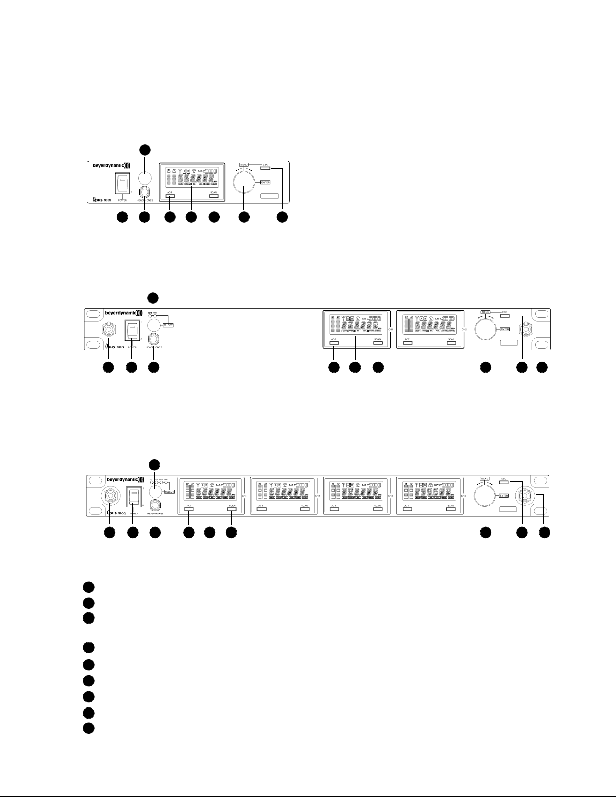
1. NE 900 Diversity Receiver
1.1 Controls and Indicators
NE 900 S front view
Power switch with LED indicator
Headphone input
Volume control for headphone input to listen to individual receiving channels
NE 900 D / Q: Press the volume control to select the receiving channel
Display
ACT button
Scan button
Menu control (for selecting different settings)
ESC button
Antenna connection when connecting the antennae on the front
1
2
3
4
5
6
7
8
9
NE 900 D front view
NE 900 Q front view
1 2 5 4 6 7 8
3
3
3
1 2 5 4 6 7 8 99
1 2 5 4 6 7 8 99
Page 7
english
45
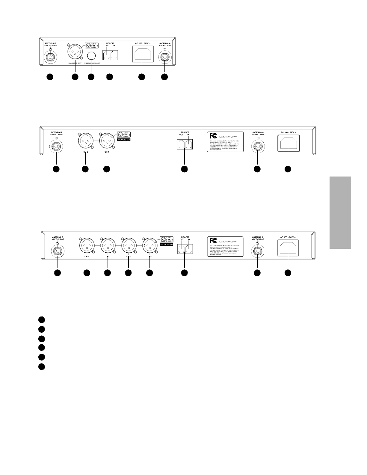
Antenna input B. TNC socket. With power supply for antenna amplifier.
AF output, 3-pin XLR, balanced
Remote connection IN / OUT
Antenna input A. TNC socket. With power supply for antenna amplifier.
Mains
NE 900 S only: AF output, 1/4" (6.35 mm) jack, unbalanced
NE 900 D rear view
NE 900 S rear view
NE 900 Q rear view
10
11
12
13
14
15
10 11 15 12 14 13
10 11 11 12 1413
10 11 11 11 11 12 1413
Page 8

46
1.2 How to connect the Antennae
Connect the antennae to the TNC sockets and ( . Set them at an angle (60°).
Please note that for diversity operation both antennae have to be connected. A weighting
circuit silently switches the signal with the better S/N ratio to the output.
1.4 LC-Display and Menu Settings
On the LC-Display all operating parameters such as RF and AF level will be shown.
Using the “Menu“ control you can select from 6 options. The selected function is
surrounded by a square frame and shown at the bottom of the LC-Display.
By selecting the ESC button you can cancel the current entry into the menu to display the
previous setting.
To select the individual receiving channels of the NE 900 D / Q for entering the menu
settings, press the menu control until the green LED between the ACT and the SCAN
button is flashing. Turn the menu control to select the receiving channel. The green LED of
the selected receiving channel will flash. Press the menu control to confirm. The green LED
will illuminate permanently.
The functions and operation are described in the following.
1.3 Setting up
1. Place the diversity receiver in the same room or area as the transmitters. Make sure the
diversity receiver is placed as close as possible to the transmitter.
2. Do not place the diversity receiver near digitally controlled equipment.
3. Connect the AF-output to the corresponding input of the mixing console or amplifier.
4. Connect the receiver to AC power.
5. Switch on the receiver . The red LED will illuminate.
6. If you use the receiver on a tabletop, please stick the supplied rubber pads to the
bottom of the receiver to ensure a sufficient ventilation.
1310
1
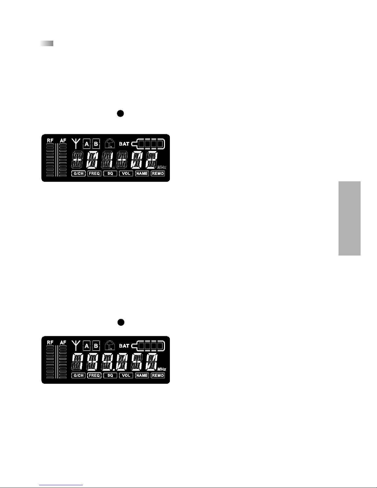
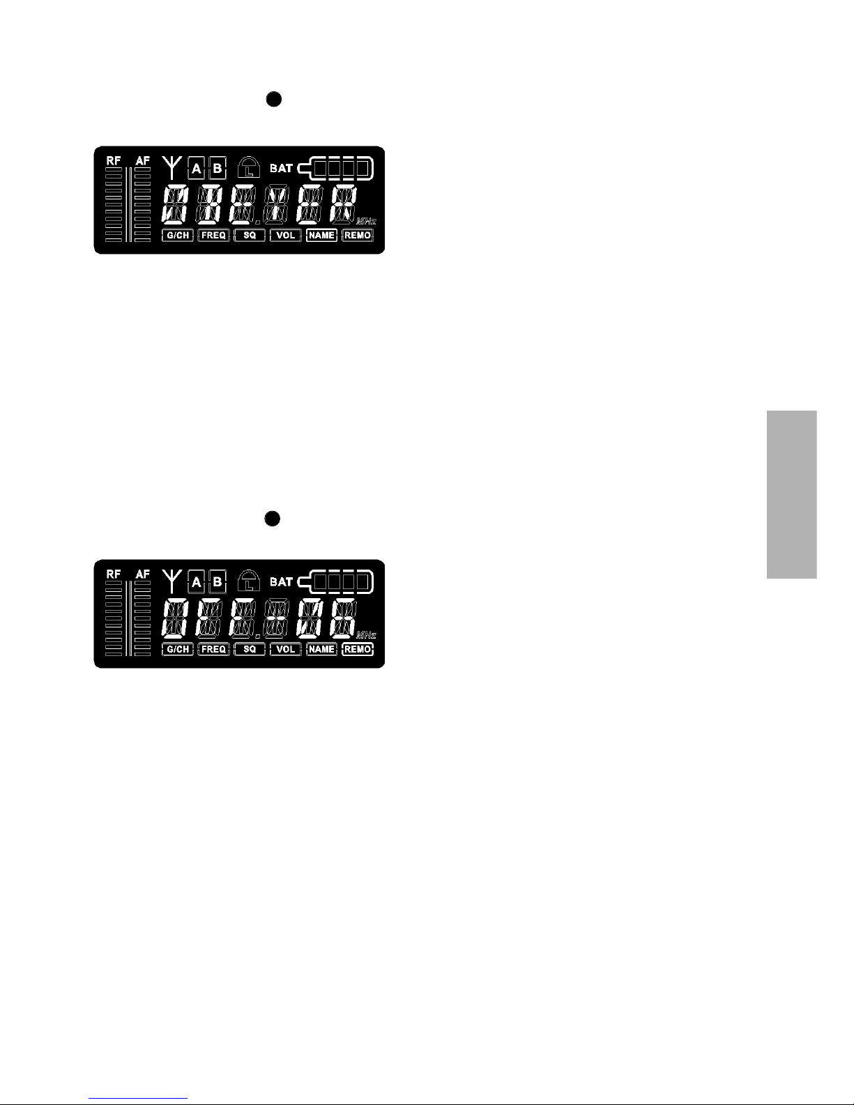
1.4.1 Diversity indication of the Receiving Channel
Each receiving module has two separate receiving circuits, one for each antenna.
The signal with the better S/N ratio is switched to the output. The received diversity channel
is shown in the LC-display.
7
7
8
Page 9
english
47
1.4.2 How to read the AF- and RF-level
The AF- or RF- level is shown in the LC-display.
1.4.3 Group, Channel
• Turn the menu control to select “G/CH”. The currently selected group and channel are
displayed.
• To change the setting, press the menu control. The group number will start flashing. Turn
the menu control to select the desired group. In order to confirm the selected group press
the menu control.
• At the same time the channel number will start flashing. Turn the menu control to select
the desired channel. In order to confirm the selected channel press the menu control.
• Press the Scan button to select a channel automatically. Press the Scan button once again
and the receiver will adjust an interference-free channel automatically within the selected
group. Press the menu control to confirm the selected channel.
1.4.4 Frequency
• Turn the menu control to select “FREQ”. The currently selected frequency is displayed.
• To change the setting press the menu control. The first three digits (MHz) will start
flashing. Turn the menu control to select the desired value. The first three digits of the
frequency (MHz) can be selected in steps of 1 MHz. In order to confirm press the menu
control.
• At the same time the last three digits (kHz) will start flashing. Turn the menu control to
select the desired value. The last three digits (kHz) can be selected in steps of 25 kHz.
• In order to confirm press the menu control.
7
7
Page 10
48
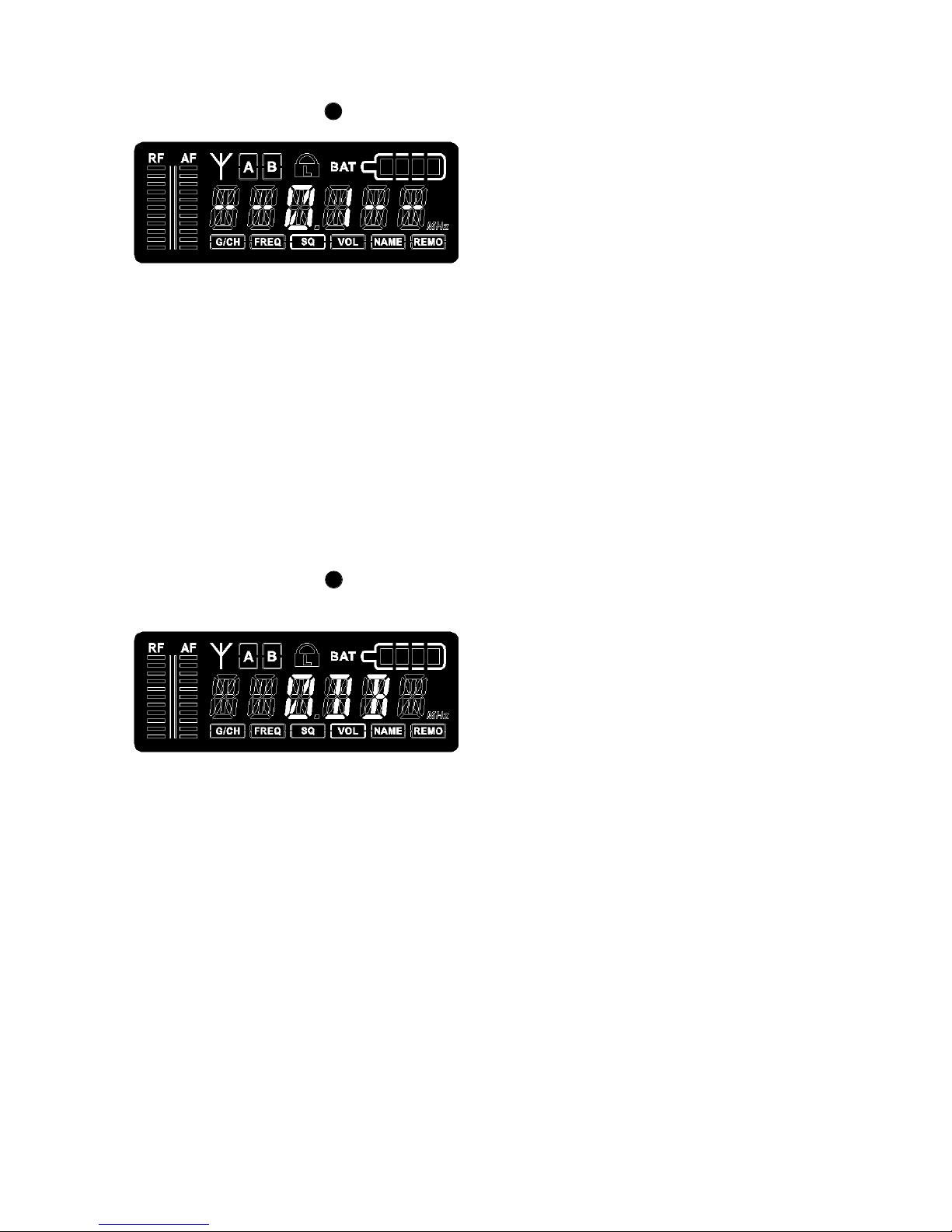
1.4.5 Squelch
• Turn the menu control to select “SQ”. The currently selected squelch is displayed.
• To change the squelch level, press the menu control. The squelch level will start to flash.
Turn the menu control to select the desired squelch level between 1 and 99. In order to
confirm the selected squelch level, press the menu control.
1.4.6 Output Level / Mute
• Turn the menu control to select “VOL”. Now you can check the output level or if the
receiver is muted.
• To change the setting, press the menu control. The current setting will start to flash.
• Turn the menu control to mute the receiver or to set the output level according to the
transmitter gain (0 dB, -10 dB, -20 dB, -30 dB).
• Press the menu control to confirm the setting.
7
7
Page 11
english
49
1.4.7 Name
• Turn the menu control to select “NAME”. A stored name is displayed or you can enter
a new name.
• To enter a new name press the menu control. The first digit will start to flash. Turn the
menu control to select the desired letter, number or character.
• In order to confirm and to enter the second digit, press the menu control. Repeat these
steps to enter all desired characters, letters or numbers. You can enter a maximum of
6 digits, symbols or letters.
1.4.8 Addressing / Control via PC
• Turn the menu control to select “REMO”. The address and the status of the remotely
controlled channel is displayed.
• To ensure a smooth control via PC, the receiving channels have to be addressed differently
before using the software.
IMPORTANT:
Each channel must have its own address. If two or more channels have the same
address, errors will occur. If the receivers are operated without a PC, it does not matter if
two or more receivers have the same address.
• When the receiver is PC-controlled “ON“ and a number are displayed. This number is the
address of the appropriate channel.
• When the receiver is operated without PC “OFF“ and the address are displayed.
• If you want to adjust or change the address, press the menu control. The number will start
to flash. Turn the menu control to select the desired address. In order to confirm the
selected address, press the menu control.
7
7
Page 12
50
1.4.9 Lock Function
The receivers have a lock function to avoid the setting of the receiver configuration
to be changed inadvertently.
How to activate the “Lock” Function
• Press the ACT and Scan buttons simultaneously.
• A red padlocked symbol is displayed.
• Now all buttons, except the ACT button are locked.
• By turning the menu control the current receiving channel configuration can still be
displayed.
• The “Lock” function is still activated when the receiver is switched off and on again.
How to deactivate the “Lock” Function
• Press the ACT and Scan buttons simultaneously. The red padlocked symbol will disappear.
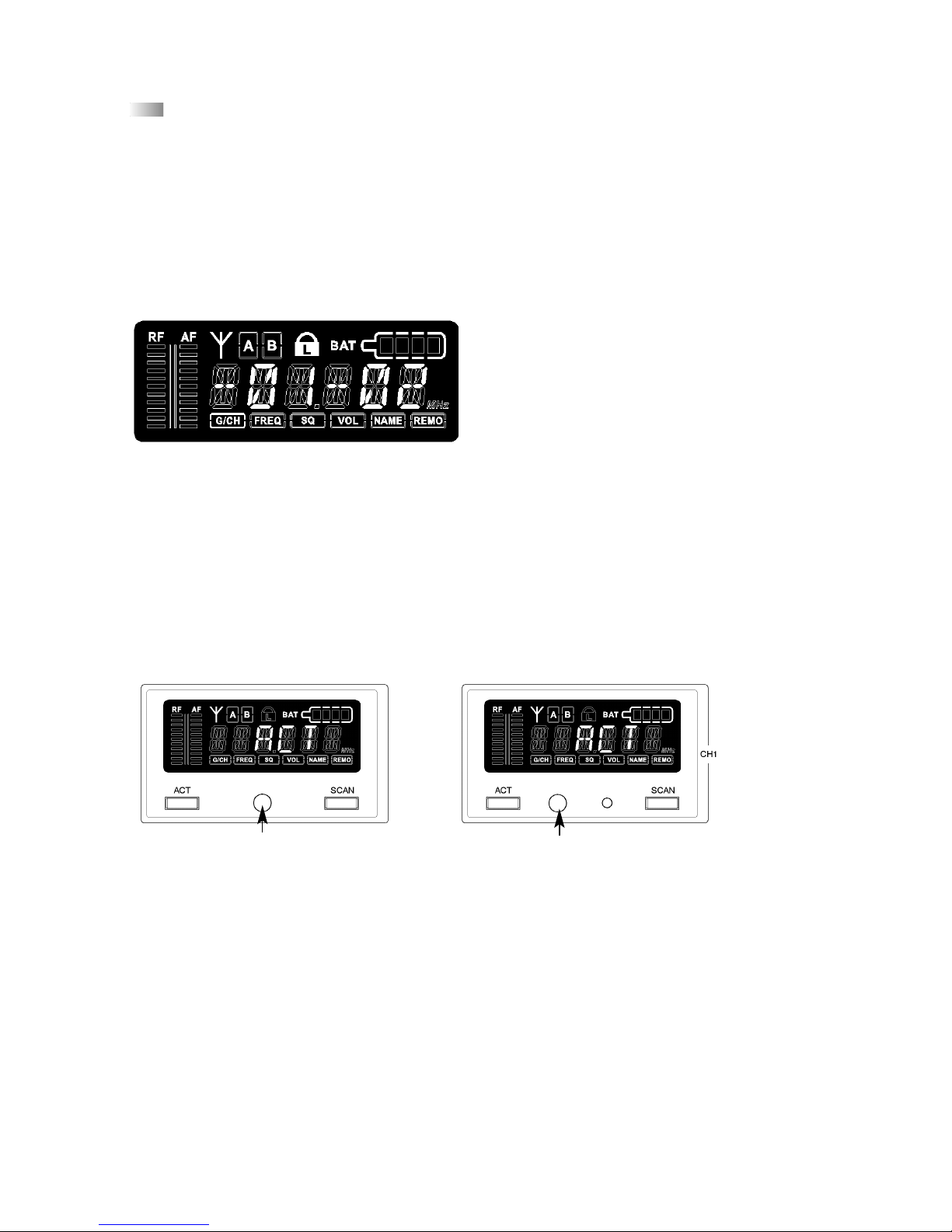
1.5 Frequency Transmission to Transmitter (ACT Function)
• The frequency of the receiver is transmitted to the appropriate transmitter via infrared.
• Press the ACT button to activate the ACT function. “ACT” is displayed.
• Hold the infrared diode of the switched on transmitter 20 cm at maximum in front of the
transmitting infrared diode of the receiver between the ACT and Scan button.
• The receiver displays “ACT” during the transmission.
• As soon as the transmitter displays the same frequency as the receiver the transmission is
finished. The receiver displays the state before starting the frequency transmission
Important:
In order to avoid interferences, the frequency of one receiver should be transmitted to one
transmitter only.
NE 900 S NE 900 D / Q
Infrared diode
Infrared diode
Page 13

english
51
1.6 Connecting and Positioning of remote Antennae
In multichannel systems we recommend the use of the AT 70 A/B UHF antenna set
consisting of antennae, cables, antenna boosters and mounting kit.
1. Connect the receiving antennae to the corresponding antenna inputs and place the
antennae to the right and left of the receiver in the operating range where the
transmitter is to be used. If necessary change the position of the antennae to improve
diversity reception.
2. The distance between the two receiving antennae should be at least 1 m.
3. The distance between transmitting and receiving antennae should be at least 3 m to
avoid overloading and interference between different channels. We therefore recommend
installing the antennae in a high position, especially in multi-channel systems.
4. If the operating range of the transmitters
is greater than the stage, the antennae
can be mounted vertically on the ceiling.
The distance between the two receiving
antennae should be approximately half
the total operating range.
Please note:
1. Install the receiving antennae in the same area as the transmitter.
2. To avoid interference do not install the antennae near digitally controlled components.
3. Keep a minimum distance of 0.5 m from metallic objects, including reinforced concrete
walls or pillars.
4. Do not bend the antenna cables at the antenna input, and ensure that they are not
subjected to undue stress.
> 1 m
> 3 m
> 1 m
AB
Stage
Auditorium
Operating range
Stage
Page 14

52
1.7 ZAS 800 Antenna Splitter
1.7.1 Controls and Indicators
(1) On/Off switch and power on LED. When the antenna splitter is switched on, the red
LED will illuminate.
(2) RF outputs to connect the receivers
(3) DC-connection to connect the DC power supply unit (12 V)
(4) Antenna sockets A/B. The antenna sockets provide a DC supply for antenna amplifiers.
(DC-Out: 8 V / 170 mA)
(5) Mounting brackets for 19" rack mounting
1.7.2 Installation
1. Mount the ZAS 800 antenna splitter and the receivers into a 19" rack by using the
mounting brackets.
2. Connect the supplied antennae to the antenna sockets A/B (4). You can also use optional
remote antennae. For mounting the antennae on the front use the supplied FB-30
mounting bracket.
3. Connect the NE 900 receivers to the ZAS 800 antenna splitter with the supplied cables.
First receiver
Second receiver
Third receiver
Fourth receiver
Page 15

english
53
4. Connect the power supply unit to the DC-connection (3) and to AC power.
(Attention: Make sure that the indicated voltage corresponds to the local voltage.)
5. Switch on the ZAS 800 antenna splitter (1).
1.7.3 General Information
1. The antenna sockets (4) feature a voltage of 8 V DC bias. To avoid a short circuit the
sockets must not touch the rack housing.
2. For the connection of remote antennae use usual 50Ω coaxial cables. The longer the
cable, the higher the RF signal loss. Therefore, the cable length should not exceed 6 m.
If you use longer cables, please use low-attenuation cables and if necessary antenna
amplifiers.
3. Use 50Ω coaxial cables to connect the receivers to the ZAS 800 antenna splitter. The
distance between these devices should be as short as possible. We recommend using the
supplied cables.
4. Supplied Accessories:
8 x RG 58 AU cables, 40 cm (TNC)
1 pair rack mount brackets supplied with antenna cables for front mounting
1 x 12 V / 500 mA power supply unit
Page 16

54
1.8 Connection to a PC
The NE 900 receiver is fitted with an RJ 11 connector with an IN and Out socket.
In order to operate several receivers with a PC they have to be connected as described
below.
• Connect the OUT-socket of the first receiver (RX 1) with the IN-socket of the second
receiver (RX 2), connect the OUT-socket of the second receiver (RX 2) with the IN-socket of
the third receiver (RX 3) and so on.
• Connect the IN-socket of the first receiver (RX 1) to the converter.
• Connect the converter to the USB interface of the PC.
• By using the PC control software, 64 channels can be operated simultaneously at
maximum.
• The distance between PC and receiver should not be too long, because to ensure high-
speed transmission the remote control cable should not be longer than 100 metres.
11
USB PORT
RJ 11
Page 17

english
55
2. S 900 Handheld Transmitter
2.1 Controls and Indicators
There are different condenser and dynamic microphone capsules for the handheld
transmitter (refer to Optional Accessories).
The S 900 C handheld transmitter has charging contacts and can be operated with the
integrated rechargeable battery pack only. Avoid a direct contact of the charging contacts to
the skin, as there is a voltage of 3 V at maximum.
S 900
S 900 C
Microphone capsule (can be unscrewed)
LC-Display
Infrared diode (at the bottom of the transmitter)
On/Off switch (at the bottom of the transmitter)
Charging contacts (at the bottom of the transmitter S 9xx C only )
S 900 M
Microphone capsule (can be unscrewed)
LC-Display
Infrared diode (on the rear)
On/Off switch
1 2
3
4
1
1
2
3
4
1
2
3
4
5
2
3
4
5
1 2
43
Page 18

56
2.2 How to insert the Batteries (S 900 and S 900 M)
1. Unscrew the battery cap of the S 900 or S 900 M counter-clockwise.
2. Insert two 1.5 V batteries into the battery compartment observing polarity markings.
Note:
The S 900 C transmitter is powered by rechargeable batteries which cannot be changed by
the user. If the rechargeable batteries have to be changed, please contact your beyerdynamic
dealer.
2.3 LC-Display
1. “ERR“ Message: When the “ERR“ message is displayed, there is an error.
ERR noo3: The frequency you want to program is above the switching bandwidth of the
transmitter. Use a receiver with an appropriate frequency group. (At this time the microphone is still operating and the frequency remains unchanged. To clear the
displayed “ERR“ message switch off the handheld transmitter and on again.)
ERR noo4: The frequency you want to program is below the switching bandwidth of the
transmitter. Use a receiver with an appropriate frequency group. (At this time the microphone is still operating and the frequency remains unchanged. To clear the
displayed “ERR“ message switch off the handheld transmitter and on again.)
2. “Group“ & “Channel“: When both indications are displayed, it means that you are
using the pre-programmed frequency of the receiver.
3. “Channel“: If “Channel“ is displayed only, it means that you are using a frequency
which is not pre-programed.
Page 19

english
57
2.4 Battery Status
• When the battery is exhausted, the LED at the bottom of the handheld transmitter will
illuminate. Replace the battery. When “PoFF“ is displayed, the transmitter is switched off,
if the battery voltage is too low.
2.5 How to switch off the Handheld Transmitter
When the ON/OFF switch at the bottom of the transmitter is switched to “OFF“, at
first “PoFF“ is displayed and as soon as the transmitter is completey off the display is blank.
Wait one second if you want to switch on the transmitter again immediately.
2.6 How to change the Microphone Capsule
There are different microphone capsules available for the handheld transmitter. If
you want to change the microphone capsule, turn it anti-clockwise to unscrew it from the
transmitter. Put the selected microphone capsule onto the transmitter and turn it clockwise
to tighten.
CM 930
Cardioid condenser microphone capsule for vocals and speech
applications. For maximum gain before feedback. Weight 191 g.
DM 960
Hypercardioid dynamic microphone capsule. Suitable for vocals and
broadcasting applications. Weight 191 g.
Page 20

58
2.7 Maintenance
• Protect the handheld transmitter from humidity, knocks and shock. Avoid dropping the
transmitter at all times.
• For cleaning metal surfaces, use a soft cloth moistened with methylated spirits or alcohol.
• As soon as your microphone sounds dull, you should clean the integrated pop shield.
Proceed as described in the following.
DM 969
Supercardioid dynamic microphone capsule. Suitable for vocals.
Weight 131 g.
EM 981
Cardioid electret condenser microphone capsule for solo vocals,
conferences and speech. Weight 191 g.
CM 930
• Unscrew the microphone capsule (turn anti-clockwise).
• Unscrew the wire mesh pop shield (turn anti-clockwise).
• Clean the pop shield under clear running water.
• Allow the pop shield to dry overnight before you replace it.
• The wire mesh pop shield cannot be cleaned in a dishwasher.
Page 21

english
59
DM 960
• Unscrew the upper part of the microphone basket (turn anticlockwise).
• Clean it under clear water.
• Let the pop shield dry overnight before you replace it.
• The upper part of the microphone basket cannot be cleaned in a
dishwasher.
EM 981
• Unscrew the microphone capsule (turn anti-clockwise).
• Unscrew the wire mesh pop shield (turn anti-clockwise).
• Clean the pop shield under clear running water.
• Allow the pop shield to dry overnight before you replace it.
• The wire mesh pop shield cannot be cleaned in a dishwasher.
DM 969
• Unscrew the upper part of the microphone basket (turn anticlockwise).
• Pull out the foam pop shield and clean it under clear running
water.
• If necessary, use a mild washing-up liquid.
• Dry it afterwards with a hairdryer or allow it to dry overnight.
• Place the dry pop shield inside the microphone basket and
replace the microphone basket by screwing it on clockwise.
Page 22

60
2.8 How to adjust the Gain
• To adjust the gain unscrew the complete microphone head with the upper shaft as
indicated by the arrows.
• Use a screwdriver to select the gain (0 dB, 10 dB, 20 dB, 30 dB).
• Lowest gain = 0 dB
Highest gain = 30 dB
Unscrew microphone head Select gain
2.9 How to set the Low-cut Filter
• The CM 930 and EM 981 microphone capsules feature a low-cut filter to compensate the
close-miking effect which ususally occurs with directional microphones. To set the low-cut
filter unscrew the complete microphone head with the upper shaft as indicated by the
arrows.
• At the bottom of the microphone head you can set the low-cut filter.
• Standard setting: linear (position Lin)
Unscrew microphone head Set low-cut filter
Page 23

english
61
3. TS 900 Beltpack Transmitter
The TS 900 C beltpack transmitter provides charging contacts and can be powered by
rechargeable batteries as well.
3.1 Controls and Indicators
AF input, 4-pin mini XLR for microphones (lavalier, neckworn mics).
For connection please refer to chapter 3.5 “AF Connection”.
ON/OFF switch (ON = switch to “ON“-position; OFF = switch to “OFF“ position).
Switch off the transmitter when not in use.
TS 900 C only: Battery status LED to indicate the power on / off and battery status.
(a) When the beltpack transmitter is switched on this LED will flash for a moment to
indicate the normal battery status.
(b) When the LED stays red after having switched on the transmitter the battery is to
weak and must be replaced.
Transmitting antenna
LC-Display
Infrared receiving diode for ACT function.
Gain control to adjust input gain.
GT/MT switch: When you use electric guitars this switch must be in the “GT“ position.
In the GT mode the gain control is deactivated. Switch to the “MT“ position when you
use condenser and wired microphones. In the MT mode the gain control is activated
Battery compartment and cover for two 1.5 V batteries (AA).
TS 900 C only: Charging contacts
Removable belt clip can be rotated 360°. To remove use a screwdriver at a 45° angle.
TS 900 C
1
5
234
6
7
8
9
11
10
1
2
3
4
5
6
7
8
9
10
11
Page 24

62
AF input, 4-pin mini XLR for microphones (lavalier, neckworn mics).
For connection please refer to chapter 3.5 “AF Connection”.
ON/OFF switch (ON = switch to “ON“-position; OFF = switch to “OFF“ position).
Switch off the transmitter when not in use.
Transmitting antenna
LC-Display
Infrared receiving diode for ACT function.
Gain control to adjust input gain.
GT/MT switch: When you use electric guitars this switch must be in the “GT“ position.
In the GT mode the gain control is deactivated. Switch to the “MT“ position when you
use condenser and wired microphones. In the MT mode the gain control is activated
Battery compartment and cover for two 1.5 V batteries (AA).
Removable belt clip can be rotated 360°. To remove use a screwdriver at a 45° angle.
TS 900 M
1
2
4
5
6
7
8
9
11
124
5
6
7
8
11
9
Page 25

english
63
This is how to remove the belt clip
3.2 How to insert the Batteries / rechargeable Battery Pack
1. Push down the two snap locks on the right and left of the battery compartment and
open it. Remove the batteries. Refer to Fig. 1.
2. Insert two 1.5 V batteries into the battery compartment observing polarity markings. Refer
to Fig. 2. The battery pack is secured mechanically against confusing the poles. Then close
the battery compartment again.
Fig. 1 Fig. 2
Fig. 1 Fig. 2
TS 900 M: Insert batteries
TS 900 C: Insert rechargeable battery pack
Page 26

64
3.3 Setting up
1. Push down the two snap locks on the right and left of the battery compartment and
open it. Now you can adjust the GT/MT switch and the gain control .
2. Make sure that the transmitter and receiver are on the same frequency.
3. The LED of the TS 900 C will flash for a moment when the transmitter is switched on and
indicates the normal battery status. When the LED fails to flash, there is no battery
inserted, the battery is leaking or inserted incorrectly. The battery status of the
TS 900 M can be seen in the LC-Display.
4. Connect the microphone or instrument to the input socket . Refer to illustration
below.
8
7
1
3.4 Adjusting the Input Gain
1. Switch on the TS 900 beltpack transmitter with the ON/OFF switch . Turn the gain
control fully anti-clockwise to minimum gain.
2. Speak into the microphone at the maximum level you expect to use. We recommend you
use the letter “U” as a spoken “U” has a relatively good sine wave shape. Adjust the
gain control to the desired gain. On the NE 900 receiver the AF level must not show
any clipping. When miking instruments, play at the maximum level you expect to use.
2
7
7
Page 27

english
65
3.5 AF Connection
(1) 2-Wire Electret Condenser Microphone Capsule
(2) 3-Wire Electret Condenser Microphone Capsule
(3) Dynamic Microphone
(4) Electric Guitar
(5) Line-in (impedance 8Ω, attenuation 10 dB)
e.g. Opus 54.18,
Opus 55.18,
Opus 56.18,
MCE 7.18
e.g. MCE 5.18,
MCE 10.18,
MCE 60.18
Page 28

66
3.6 LC-Display
1. “ERR“ Message: When the “ERR“ message is displayed, there is an error.
ERR noo3: The frequency you want to program is above the switching bandwidth of the
transmitter. Use a receiver with an appropriate frequency group. (At this time the microphone is still operating and the frequency remains unchanged. To clear the displayed
“ERR“ message switch off the transmitter and on again.)
ERR noo4: The frequency you want to program is below the switching bandwidth of the
transmitter. Use a receiver with an appropriate frequency group. (At this time the microphone is still operating and the frequency remains unchanged. To clear the displayed
“ERR“ message switch off the transmitter and on again.)
2. “Group“ & “Channel“: When both indications are displayed, it means that you are
using the pre-programmed frequency of the receiver.
3. “Channel“: If “Channel“ is displayed only, it means that you are using a frequency
which is not pre-programed.
3.7 Battery Status
• When the battery is exhausted, the LED (TS 900 C only) will illuminate. Replace the
battery. When “PoFF“ is displayed, the transmitter is switched off to avoid an overdischarge of the battery.
3.8 How to switch off the Beltpack Transmitter
When the ON/OFF switch is switched to “OFF“, at first “PoFF“ is displayed and as soon
as the transmitter is completey off the display is blank. Wait one second if you want to
switch on the transmitter again immediately.
3
Page 29

english
67
4. General Instructions for all Transmitters
4.1 Battery Change
• Switch the transmitter off before changing the battery.
• If you do not use the transmitter for several weeks or months, please remove the battery
as it can leak after some time and damage parts of the transmitter. Even “leak proof” may
leak after some time. Damage caused by leaking batteries is not covered under warranty.
• Clean the battery contacts from time to time by using a soft cloth moistened with spirits
or alcohol.
• Please do not throw used battery packs away with your household rubbish, but take them
to your local collection points.
• When using rechargeable batteries use beyerdynamic chargers.
4.2 Before the Soundcheck
1. Check the transmitter battery and replace or recharge it if necessary. Use fresh alkaline
batteries only.
2. When the transmitter is switched off and immediately switched on again, it is possible
that the transmitter remains switched off. The cause is the function that allows to switch
the transmitter on / off silently. Should this problem occur during operation, the battery
might have contact problems. After switching off the transmitter you should wait at least 1
second, until you switch the transmitter on again.
3. Check the performance area for dropouts. If you find any dropouts, try to eliminate
them by repositioning the antennae or the receiver.
4. The receiving antennas should be placed so that the distance between receiving
antennae and transmitter is at least 3 m. If necessary, use remote antennae (AT 70 A/B).
4.3 Positioning of Transmitters if Interference occurs
Put all transmitters in their position and switch them on. Switch each transmitter off
one at a time and check the receiver for interference in the corresponding channel.
The interference is possibly eliminated by changing the squelch (refer also to chapter
1.4.5 “Squelch”.
When using multi-channel-systems, please contact beyerdynamic. Interferences can also be
caused by DVB-T television transmitters in the neighbourhood.
4.4 What to Do to avoid Feedback
Feedback is caused by your microphone getting too close to a loudspeaker.
We recommend:
• Move away from the loudspeaker.
• Turn the microphone away from the loudspeaker.
Page 30

68
5. Trouble Shooting
5.1 NE 900 Diversity Receiver
5.2 Handheld and Beltpack Transmitter
•
Power supply is interrupted, power
supply unit is not connected to the mains
and / or to receiver
• Connect the receiver to AC power
•
Switch on the transmitter
• Adjust the correct frequency with the
ACT function
• Check the antenna cables
•
Input amplifier of the connected mixer is
overloaded
• Use the gain control of the mixer or
adjust the volume
Distorted sound
No reception
No function
Problem Possible Cause Solution
• Transmitter is not switched on
• Transmitter works on a different
channel
• Defect in the antenna cables with
remote antennae
“CLIP” indication on
receiver
•
Transmitter is overloaded
• Reduce the sensitivity of the
transmitter or increase the distance
between microphone and sound
source.
No sound, RF-indication
is okay, AF- indication is
missing during
modulation
•
Wrong indication caused by strong
interference signals
• No microphone connected to TS 900
beltpack transmitter
• Choose another receiving channel
• Connect a suitable microphone
• Transmitter and receiver have different
frequencies
• Insufficient battery voltage
• Poor battery contact, battery inserted
incorrectly
• Check if transmitter and receiver
have the same frequency
• Replace the batteries or recharge
them, if you use rechargeable
batteries
• Check the battery and insert it again
•
Transmission distance between transmitter
and receiver is too big
• Reduce the distance between
transmitter and receiver
No RF-indication at
the receiver
•
Interference from other transmitters
• Two transmitters are on the same
frequency
• Battery of the transmitter is too weak
• Switch off the other transmitters
• Change the frequency of one
transmitter
• Replace the batteries
Noise/chirping
No function
Problem Possible Cause Solution
Page 31

english
69
6. Maintenance
In the unlikely event of equipment failure, the product should be returned to your
beyerdynamic dealer. Unauthorised attempts at repair may invalidate the warranty.
7. Licensing
In most countries around the world, wireless systems must be approved for use by
the authorities and it may be necessary to obtain a licence to use it legally. Your local
beyerdynamic dealer will be able to give you details on wireless system regulations for your
area.
The components of the Opus 900 system are approved according to the directive 99/5/EEC:
TS 900 M, TS 900 C
SDM 960 M, SCM 934 M, SDM 960, SDM 969, SDM 969 C, SEM 981 C
under the CE 0682 ! identification.
8. Components
Receiver
NE 900 Q 4-channel true diversity receiver, 668 - 692 MHz. . . . . . . . . . . Order # 489.972
NE 900 Q same as above, but 774 - 798 MHz. . . . . . . . . . . . . . . . . . . . . . Order # 489.980
NE 900 Q same as above, but 790 - 814 MHz*. . . . . . . . . . . . . . . . . . . . . Order # 489.999
NE 900 Q same as above, but 841 - 865 MHz*. . . . . . . . . . . . . . . . . . . . . Order # 490.008
NE 900 D 2-channel true diversity receiver, 668 - 692 MHz. . . . . . . . . . . Order # 490.016
NE 900 D same as above, but 774 - 798 MHz. . . . . . . . . . . . . . . . . . . . . . Order # 490.024
NE 900 D same as above, but 790 - 814 MHz*. . . . . . . . . . . . . . . . . . . . . Order # 490.032
NE 900 D same as above, but 841 - 865 MHz*. . . . . . . . . . . . . . . . . . . . . Order # 490.040
NE 900 S 1-channel true diversity receiver, 668 - 692 MHz. . . . . . . . . . . Order # 490.059
NE 900 S same as above, but 774 - 798 MHz. . . . . . . . . . . . . . . . . . . . . . Order # 490.067
NE 900 S same as above, but 790 - 814 MHz*. . . . . . . . . . . . . . . . . . . . . Order # 490.075
NE 900 S same as above, but 841 - 865 MHz*. . . . . . . . . . . . . . . . . . . . . Order # 490.083
Handheld Transmitter
SDM 960 M UHF handheld transmitter, metal housing,
DM 960 microphone capsule, 668 - 692 MHz . . . . . . . . . . . . . Order # 490.091
SDM 960 M same as above, but 774 - 798 MHz. . . . . . . . . . . . . . . . . . . . . . Order # 490.105
SDM 960 M same as above, but 790 - 814 MHz*. . . . . . . . . . . . . . . . . . . . . Order # 490.113
SDM 960 M same as above, but 841 - 865 MHz*. . . . . . . . . . . . . . . . . . . . . Order # 490.121
SCM 930 M UHF handheld transmitter, metal housing,
CM 930 microphone capsule, 668 - 692 MHz. . . . . . . . . . . . . . Order # 490.148
SCM 930 M same as above, but 774 - 798 MHz. . . . . . . . . . . . . . . . . . . . . . Order # 490.156
SCM 930 M same as above, but 790 - 814 MHz*. . . . . . . . . . . . . . . . . . . . . Order # 490.164
SCM 930 M same as above, but 841 - 865 MHz*. . . . . . . . . . . . . . . . . . . . . Order # 490.172
SDM 960 UHF handheld transmitter, plastic housing,
DM 960 microphone capsule, 668 - 692 MHz . . . . . . . . . . . . . Order # 490.180
SDM 960 same as above, but 774 - 798 MHz. . . . . . . . . . . . . . . . . . . . . . Order # 490.199
SDM 960 same as above, but 790 - 814 MHz*. . . . . . . . . . . . . . . . . . . . . Order # 490.202
SDM 960 same as above, but 841 - 865 MHz*. . . . . . . . . . . . . . . . . . . . . Order # 490.210
*NOT for use in the USA or Canada
Page 32

70
SDM 969 UHF handheld transmitter, plastic housing,
DM 969 microphone capsule, 668 - 692 MHz . . . . . . . . . . . . . Order # 490.229
SDM 969 same as above, but 774 - 798 MHz. . . . . . . . . . . . . . . . . . . . . . Order # 490.237
SDM 969 same as above, but 790 - 814 MHz*. . . . . . . . . . . . . . . . . . . . . Order # 490.245
SDM 969 same as above, but 841 - 865 MHz*. . . . . . . . . . . . . . . . . . . . . Order # 490.253
SDM 969 C same as SDM 969, but with charging contacts,
668 - 692 MHz . . . . . . . . . . . . . . . . . . . . . . . . . . . . . . . . . . . . . . Order # 490.326
SDM 969 C same as above, but 774 - 798 MHz. . . . . . . . . . . . . . . . . . . . . . Order # 490.334
SDM 969 C same as above, but 790 - 814 MHz*. . . . . . . . . . . . . . . . . . . . . Order # 490.342
SDM 969 C same as above, but 841 - 865 MHz*. . . . . . . . . . . . . . . . . . . . . Order # 490.350
SEM 981 C UHF handheld transmitter, plastic housing,
EM 981 microphone capsule,
with charging contacts, 668 - 692 MHz . . . . . . . . . . . . . . . . . . Order # 490.369
SEM 981 C same as above, but 774 - 798 MHz. . . . . . . . . . . . . . . . . . . . . . Order # 490.377
SEM 981 C same as above, but 790 - 814 MHz*. . . . . . . . . . . . . . . . . . . . . Order # 490.385
SEM 981 C same as above, but 841 - 865 MHz*. . . . . . . . . . . . . . . . . . . . . Order # 490.393
S 900 UHF handheld transmitter, plastic housing, black,
668 - 692 MHz . . . . . . . . . . . . . . . . . . . . . . . . . . . . . . . . . . . . . . Order # 490.679
S 900 same as above, but 774 - 798 MHz. . . . . . . . . . . . . . . . . . . . . . Order # 490.687
S 900 same as above, but 790 - 814 MHz*. . . . . . . . . . . . . . . . . . . . . Order # 490.695
S 900 same as above, but 841 - 865 MHz*. . . . . . . . . . . . . . . . . . . . . Order # 490.709
S 900 C UHF handheld transmitter, plastic housing, black,
with charging contacts, 668 - 692 MHz . . . . . . . . . . . . . . . . . . Order # 490.601
S 900 C same as above, but 774 - 798 MHz . . . . . . . . . . . . . . . . . . . . . . Order # 490.628
S 900 C same as above, but 790 - 814 MHz* . . . . . . . . . . . . . . . . . . . . . Order # 490.636
S 900 C same as above, but 841 - 865 MHz* . . . . . . . . . . . . . . . . . . . . . Order # 490.644
S 900 M UHF handheld transmitter, metal housing, black,
668 - 692 MHz . . . . . . . . . . . . . . . . . . . . . . . . . . . . . . . . . . . . . . Order # 490.555
S 900 M same as above, but 774 - 798 MHz. . . . . . . . . . . . . . . . . . . . . . Order # 490.563
S 900 M same as above, but 790 - 814 MHz*. . . . . . . . . . . . . . . . . . . . . Order # 490.571
S 900 M same as above, but 841 - 865 MHz*. . . . . . . . . . . . . . . . . . . . . Order # 490.598
Beltpack Transmitter
TS 900 M UHF beltpack transmitter, metal housing, 668 - 692 MHz . . . Order # 490.407
TS 900 M same as above, but 774 - 798 MHz. . . . . . . . . . . . . . . . . . . . . . Order # 490.415
TS 900 M same as above, but 790 - 814 MHz*. . . . . . . . . . . . . . . . . . . . . Order # 490.423
TS 900 M same as above, but 841 - 865 MHz*. . . . . . . . . . . . . . . . . . . . . Order # 490.431
TS 900 C UHF beltpack transmitter, plastic housing,
with charging contacts, 668 - 692 MHz . . . . . . . . . . . . . . . . . . Order # 490.458
TS 900 C same as above, but 774 - 798 MHz. . . . . . . . . . . . . . . . . . . . . . Order # 490.466
TS 900 C same as above, but 790 - 814 MHz*. . . . . . . . . . . . . . . . . . . . . Order # 490.474
TS 900 C same as above, but 841 - 865 MHz*. . . . . . . . . . . . . . . . . . . . . Order # 490.482
9. Optional Accessories
NE 900 Diversity Receiver
Antenna Splitter
ZAS 800 UHF antenna splitter, active, 19" housing,
incl. cable set, 740 - 764 MHz . . . . . . . . . . . . . . . . . . . . . . . . . . Order # 467.073
*NOT for use in the USA or Canada
Page 33

english
71
ZAS 800 same as above, but 774 - 798 MHz. . . . . . . . . . . . . . . . . . . . . . Order # 473.081
ZAS 800 same as above, but 790 - 814 MHz*. . . . . . . . . . . . . . . . . . . . . Order # 491.667
ZAS 800 same as above, but 841 - 865 MHz*. . . . . . . . . . . . . . . . . . . . . Order # 491.675
Antennae
AT 70 A/B Set UHF antenna set for NE 900, cpl. with
2 x AT 70 B TNC booster, 2 x AT 70 TNC antenna and
2 x MS 10 mounting kit . . . . . . . . . . . . . . . . . . . . . . . . . . . . . . . Order # 459.976
FBC 71 Cable rear-to-front for NE 900 and ZAS 800 (1 pair). . . . . . . . Order # 469.823
FB 72 Mounting bracket, metal, for mounting of ZAS 800
into a 19"-rack . . . . . . . . . . . . . . . . . . . . . . . . . . . . . . . . . . . . . . Order # 460.036
Individual Components - Software
USB Adapter Opus 900 USB Adapter . . . . . . . . . . . . . . . . . . . . . . . . . . . . . . . Order # 490.776
RJ 11 Cable Opus 900 RJ 11 . . . . . . . . . . . . . . . . . . . . . . . . . . . . . . . . . . . . . . Order # 490.784
CD ROM Opus 900 CD-ROM . . . . . . . . . . . . . . . . . . . . . . . . . . . . . . . . . . . Order # 490.792
S 900 Handheld Transmitter
Microphone Capsules
CM 930 B Condenser, cardioid, black . . . . . . . . . . . . . . . . . . . . . . . . . . . . Order # 490.539
CM 930 S Condenser, cardioid, silver. . . . . . . . . . . . . . . . . . . . . . . . . . . . . Order # 491.721
DM 960 B Dynamic, hypercardioid, black . . . . . . . . . . . . . . . . . . . . . . . . . Order # 490.490
DM 960 S Dynamic, hypercardioid, silver . . . . . . . . . . . . . . . . . . . . . . . . . Order # 490.504
DM 969 S Dynamic, supercardioid, silver. . . . . . . . . . . . . . . . . . . . . . . . . . Order # 490.512
EM 981 S Electret condenser, cardioid, silver . . . . . . . . . . . . . . . . . . . . . . Order # 490.520
TS 900 Beltpack Transmitter
Microphones
Opus 54.18 Neckworn microphone, cardioid, black . . . . . . . . . . . . . . . . . . Order # 464.945
Opus 55.18 Neckworn microphone, omnidirectional, black. . . . . . . . . . . . Order # 465.356
MCE 5.18 Condenser clip-on microphone, omnidirectional, black . . . . . Order # 471.879
MCE 10.18 Condenser clip-on microphone, cardioid, black . . . . . . . . . . . Order # 471.895
MCE 60.18 Condenser clip-on microphone, omnidirectional, black . . . . . Order # 469.548
Cable
MJ 41 G Cable for instruments with 1/4" jack (6.35 mm),
for TS 900 (C / M) beltpack transmitter . . . . . . . . . . . . . . . . . . Order # 460.087
10. Technical Specifications
NE 900 Diversity Receiver
Operating principle . . . . . . . . . . . . . . . True diversity receiver (UHF)
Frequency range . . . . . . . . . . . . . . . . . 668 - 692 MHz
774 - 798 MHz
790 - 814 MHz*
841 - 865 MHz*
Power consumption. . . . . . . . . . . . . . . NE 900 Q: 25 W
NE 900 D: 15 W
Power consumption in
stand-by mode . . . . . . . . . . . . . . . . . . . NE 900 Q, D: 0.2 W
Switching bandwidth . . . . . . . . . . . . . 24 MHz
*NOT for use in the USA or Canada
Page 34

72
Sensitivity . . . . . . . . . . . . . . . . . . . . . . . 2 µV
Antenna connection . . . . . . . . . . . . . . 2 x TNC
Nominal deviation . . . . . . . . . . . . . . . . ± 40 kHz
Output level . . . . . . . . . . . . . . . . . . . . . 1.2 V
Compander system . . . . . . . . . . . . . . . NE572
Signal-to-noise ratio . . . . . . . . . . . . . . > 110 dB(A)
T.H.D. . . . . . . . . . . . . . . . . . . . . . . . . . . < 0.5% at 1 kHz
Squelch . . . . . . . . . . . . . . . . . . . . . . . . . 2 µV - 1 mV, adjustable
Power supply . . . . . . . . . . . . . . . . . . . . 12 V - 15 V DC
Mains . . . . . . . . . . . . . . . . . . . . . . . . . . 110 V - 240 V AC
Dimensions . . . . . . . . . . . . . . . . . . . . . . NE 900 S (L x W x H) 210 x 235 x 43 mm
NE 900 D / Q (L x W x H) 482 x 270 x 43 mm
Weight . . . . . . . . . . . . . . . . . . . . . . . . . NE 900 D 2.75 kg
NE 900 Q 3.1 kg
Minimum distance of the profiles
when mounting into a 19" rack. . . . . 446 mm
SCM 930 M / SDM 960 / SDM 960 M / SDM 969 / SEM 981
Handheld Transmitter
Polar pattern . . . . . . . . . . . . . . . . . . . . Hypercardioid (SDM 960, SDM 960 M)
Supercardioid (SDM 969)
Cardioid (SEM 981, SCM 930 M)
Transducer type . . . . . . . . . . . . . . . . . . True condenser (SCM 930 M)
Dynamic (SDM 960, SDM 960 M, SDM 969)
Electret condenser (SEM 981)
Frequency range . . . . . . . . . . . . . . . . . 668 - 692 MHz
774 - 798 MHz
790 - 814 MHz*
841 - 865 MHz*
Modulation . . . . . . . . . . . . . . . . . . . . . FM
Nominal deviation . . . . . . . . . . . . . . . . ± 40 kHz
Radiated transmitter power . . . . . . . . 10 mW
Compander system . . . . . . . . . . . . . . . NE572
Max. SPL . . . . . . . . . . . . . . . . . . . . . . . . 146 dB
AF transmission range
SDM 960, SDM 960 M. . . . . . . . . . . . . . 55 - 18,000 Hz (close miking 2 cm) at 80 dB SPL
SDM 969 65 - 16,000 Hz (close miking 2 cm) at 80 dB SPL
SEM 981 50 - 18,000 Hz (close miking 2 cm) at 80 dB SPL
SCM 930 40 - 20,000 Hz (close miking 2 cm) at 80 dB SPL
Rear attenuation . . . . . . . . . . . . . . . . . -20 dB at 1 kHz / 120° (SDM 960, SDM 960 M)
-15 dB at 1 kHz / 145° (SDM 969)
-15 dB at 1 kHz / 180° (SEM 981)
-20 dB at 1 kHz / 180° (SCM 930)
Signal-to-noise ratio . . . . . . . . . . . . . . > 110 dB
T.H.D. . . . . . . . . . . . . . . . . . . . . . . . . . . < 0.5% at 1 kHz
Transmission range . . . . . . . . . . . . . . . 100 m
Power supply . . . . . . . . . . . . . . . . . . . . 2 x 1.5 V batteries (AA) or rechargeable batteries
Current consumption. . . . . . . . . . . . . . approx. 85 mA
Operating time . . . . . . . . . . . . . . . . . . > 20 hours with alkaline batteries
Dimensions
Length . . . . . . . . . . . . . . . . . . . . . . . . . S 900: 188 mm S 900 C: 188 mm S 900 M: 210.5 mm
Shaftø . . . . . . . . . . . . . . . . . . . . . . . . . . S 900: 38 mm S 900 C: 38 mm S 900 M: 38 mm
Weight with batteries . . . . . . . . . . . . . S 900: 168 g S 900 C: 169 g S 900 M: 172 g
*NOT for use in the USA or Canada
Page 35

english
73
TS 900 (C / M) Beltpack Transmitter
Frequency range . . . . . . . . . . . . . . . . . 668 - 692 MHz
774 - 798 MHz
790 - 814 MHz*
841 - 865 MHz*
Modulation . . . . . . . . . . . . . . . . . . . . . FM
Nominal deviation . . . . . . . . . . . . . . . . ± 40 kHz
Radiated transmitter power . . . . . . . . 20 mW
Compander system . . . . . . . . . . . . . . . NE572
Signal-to-noise ratio . . . . . . . . . . . . . . > 110 dB
T.H.D. . . . . . . . . . . . . . . . . . . . . . . . . . . < 0.5% at 1 kHz
Frequency response . . . . . . . . . . . . . . . 50 Hz - 18,000 Hz
Gain . . . . . . . . . . . . . . . . . . . . . . . . . . . 10 mV - 0.3 V adjustable, at nominal deviation
Power supply . . . . . . . . . . . . . . . . . . . . 2 x 1.5 V batteries (AA) or rechargeable batteries
Current consumption. . . . . . . . . . . . . . approx. 85 mA
Operating time . . . . . . . . . . . . . . . . . . > 20 hours with alkaline batteries
Dimensions (L x W x D) . . . . . . . . . . . . TS 900 C: 110 x 63 x 21.5 mm
TS 900 M: 110 x 65.5 x 24.5 mm
Weight . . . . . . . . . . . . . . . . . . . . . . . . . TS 900 C: 155 g
TS 900 M: 156 g
4-pin connection . . . . . . . . . . . . . . . . . Pin 1 = Ground, Pin 2 = IN1, Pin 3 = IN2,
Pin 4 = +5 V; refer also to chapter 3.5 “AF Connection”
ZAS 800 Antenna Splitter
Inputs . . . . . . . . . . . . . . . . . . . . . . . . . . 2 x 50 Ω (TNC)
Outputs. . . . . . . . . . . . . . . . . . . . . . . . . 8 x 50 Ω (TNC)
Frequency range . . . . . . . . . . . . . . . . . depending on the version
Amplification . . . . . . . . . . . . . . . . . . . . 0 dB ±3 dB
Decoupling attenuation . . . . . . . . . . . > 15 dB
Power supply . . . . . . . . . . . . . . . . . . . . 12 V - 15 V DC, 1A current min.
Mains . . . . . . . . . . . . . . . . . . . . . . . . . . 110 - 240 V AC
Current consumption. . . . . . . . . . . . . . approx. 170 mA
Dimensions (L x W x H) . . . . . . . . . . . . 482 x 190 x 44 mm
Weight . . . . . . . . . . . . . . . . . . . . . . . . . approx. 1547 g
*NOT for use in the USA or Canada
The following models are available for the Japanese market:
S 900 frequency range 797.250 – 805.750 and 806.125 – 809.750 . . . . . Order # 492.868
S 900 C frequency range 797.250 – 805.750 and 806.125 – 809.750 . . . . . Order # 492.884
S 900 M frequency range 797.250 – 805.750 and 806.125 – 809.750 . . . . . Order # 492.833
TS 900 C frequency range 797.250 – 805.750 and 806.125 – 809.750 . . . . . Order # 492.922
TS 900 M frequency range 797.250 – 805.750 and 806.125 – 809.750 . . . . . Order # 492.906
NE 900 S frequency range 797.250 – 805.750 and 806.125 – 809.750 . . . . . Order # 492.817
NE 900 D frequency range 797.250 – 805.750 and 806.125 – 809.750 . . . . . Order # 492.795
NE 900 Q frequency range 797.250 – 805.750 and 806.125 – 809.750 . . . . . Order # 492.779
Page 36

141
EC-DECLARATION
OF
CONFORMITY
Application of
Council Directive: 99/5/EEC
R&TTE Directive
73/23/EEC, 93/68/EEC
Low Voltage Directive
Standards to which EN 301 489-1/-9: 2000
Conformity is declared: EN 300 422-1/-2: 2000
EN 60 065 (Safety)
Manufacturer's Name: beyerdynamic GmbH & Co. KG
Manufacturer's Address: Theresienstrasse 8, 74072 Heilbronn, Germany
Type of Equipment: Wireless Microphone System Opus 900
Model Number/s: Transmitters S 900, S 900 C, S 900 M,
TS 900, TS 900 M
I, the undersigned, as an employee of beyerdynamic, hereby declare that the
equipment specified conforms to the above Directive and Standards.
Manufacturer’s Signature:
Date: October 1, 2006
Full Name: Ulrich Roth
Position: Director of R&D
0682 !
Page 37

140
EC-DECLARATION
OF
CONFORMITY
Application of
Council Directive: 99/5/EEC
R&TTE Directive
73/23/EEC, 93/68/EEC
Low Voltage Directive
Standards to which EN 301 489-1/-9: 2000
Conformity is declared: EN 300 422-1/-2: 2000
EN 60 065 (Safety)
Manufacturer's Name: beyerdynamic GmbH & Co. KG
Manufacturer's Address: Theresienstrasse 8, 74072 Heilbronn, Germany
Type of Equipment: Wireless Microphone System Opus 900
Model Number/s: Receivers NE 900 D, NE 900 Q, NE 900 S
I, the undersigned, as an employee of beyerdynamic, hereby declare that the
equipment specified conforms to the above Directive and Standards.
Manufacturer’s Signature:
Date: October 1, 2006
Full Name: Ulrich Roth
Position: Director of R&D
0682 !
Page 38

DEF 7/BA Opus 900 (08.07)/586.153 • Abbildungen nicht vertragsbindend. Änderungen und Irrtümer vorbehalten • Non-contractual illustrations. Subject to change without notice. •
Illustrations non contractuelles.
Sous réserve de modifications.
beyerdynamic GmbH & Co. KG
Theresienstr. 8
D-74072 Heilbronn, Germany
Tel. +49 (0 )71 31 / 617-0
Fax +49 (0 )71 31 / 617-224
E-mail: info@beyerdynamic.de
Internet: www.beyerdynamic.de
beyerdynamic Inc. USA
56 Central Ave.
Farmingdale, NY 11735
Tel. +1 (631) 293-3200
Fax +1 (631) 293-3288
E-mail: salesUSA@beyerdynamic.com
Internet: www.beyerdynamic.com
beyerdynamic U.K. Ltd.
17 Albert Drive
Burgess Hill RH15 9TN
Tel. +44 (0)1444 / 258 258
Fax +44 (0)1444 / 258444
E-mail: sales@beyerdynamic.co.uk
Internet: www.beyerdynamic.co.uk
 Loading...