

Page 1

BEDIENUNGSANLEITUNG
OPERATING INSTRUCTIONS
NOTICE D’UTILISATION
Opus 100
Drahtloses System
Wireless System
Système sans fil
Page 2
16
OPERATING INSTRUCTIONS Opus 100
Thank you for selecting the Opus 100 wireless system. Please take some time to read
carefully through this manual before setting up the equipment.
The Opus 100 system has a single frequency in the VHF frequency range 174 to 236 MHz or in
the UHF frequency range 798 to 862 MHz.
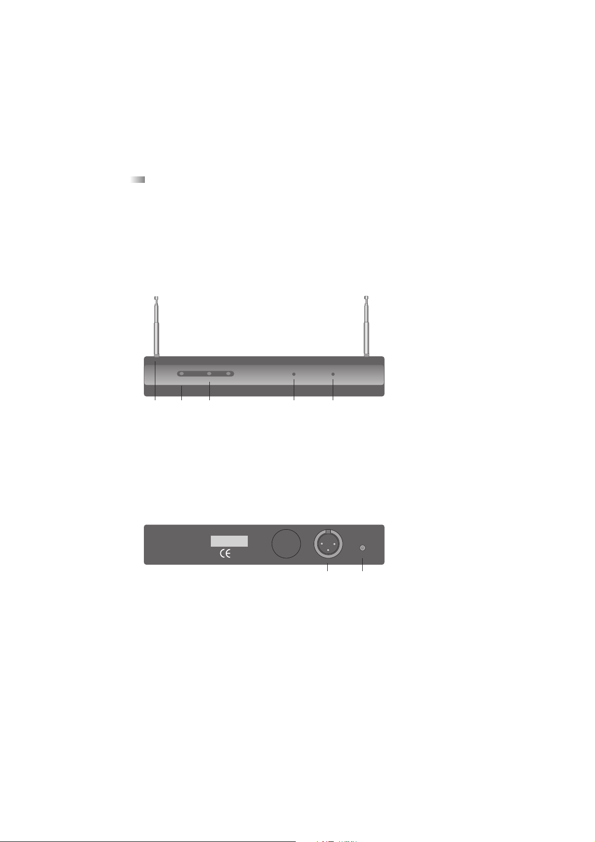
1. NE 100 Diversity Receiver
1.1 Controls and Indicators
Front view
(1) Telescopic antennae (fixed)
(2) Power On / Mute LED
(3) Diversity LEDs A/B (Antenna A Antenna B)
(4) Squelch control
(5) Output level control (balanced output signal, 3-pin XLR)
Rear view
(6) AF-output, 3-pin XLR, balanced output signal
(7) DC-connection for external power supply unit
NE 100 V VHF Receiver
beyerdynamic))))
Opus
On/Mute Antenna A Antenna B
Squelch
min max
Out Level
min max
(1) (2) (3) (4) (5)
Output
12V AC/DC
xxx,xxx MHZ
Made in EC
beyerdynamic))))
Wireless Stage Systems
(6) (7)
Page 3

english
17
1.2 Antennae
Fully extend the antennae and set them at an angle of 60° between each antenna. The
two antennae are positioned this way to achieve the best pick-up reception.
1.3 Setting up
1. Place the NE 100 diversity receiver in the same room or area as the transmitters. Ensure
that the NE 100 is installed as close as possible to the mixing console or amplifier so that
all indications can be seen at all times.
2. Do not place the NE 100 diversity receiver near digitally controlled equipment.
3. Connect the XLR-output (6) to the corresponding input of the mixing console or amplifier.
Using the output level control (5) you can adjust the gain.
4. Make sure the mains voltage shown on the power supply unit corresponds to the local
mains voltage.
5. Connect the power supply unit to the receiver and to AC power. The receiver has no
separate On/Off switch. The power On / Mute LED (2) is illuminated red.
6. To adjust the input gain turn the squelch control (4) to maximum.
7. If the On/Mute LED (2) is illuminated green when there is no transmitter switched on, there
is RF noise present. Turn the squelch control (4) counter clockwise to minimum until the RF
noise is disappeared.
8. As soon as you switch on the transmitter, the On/Mute LED (2) should go out and the
diversity LEDs (3) indicate which antenna input is active.
1.4 Diversity Indication of the Receiving Channel
The NE 100 has two separate receiving circuits for each of the antennae A and B. The
signal with the better S/N ratio is silently switched to the output. The received diversity channel
A or B is shown on the LEDs (3).
1.5 Squelch
Switch off the transmitter before you change the squelch. Now the receiver should be
muted. If it is not, then slowly adjust the squelch (4) until all unwanted signals are muted. As
soon as the receiver has been muted, the On/Mute LED (2) is illuminated red. Setting the level
too high, however, will reduce the range of your system.
Squelch control (4) to the left = minimum range
Squelch control (4) to the right = maximum range - Caution: Interferences can occur!
Page 4
18
1.6 Setting the Gain
First adjust the gain of your transmitter (only TS 100; refer to chapter 3.3). Once the
transmitter gain is optimised, it is necessary to match the receiver’s output gain to your mixing
console or PA system. Adjust the gain control (5). Setting the gain too high may cause distortion.
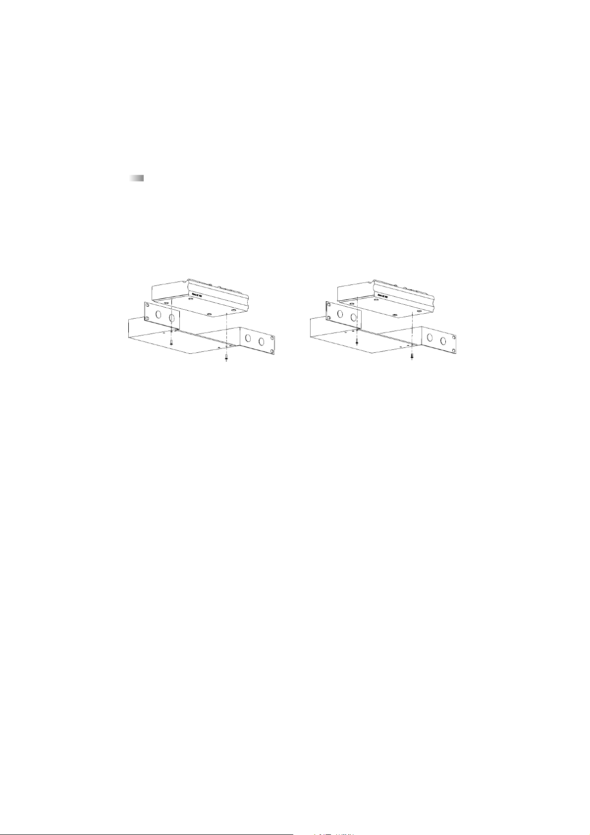
1.7 Mounting NE 100 into ZTE 100/200 Mounting Bracket
• For mounting the NE 100 receiver into the ZTE 100/200 mounting bracket the NE 100 has
one hole on the right and on the left side at the bottom.
• The NE 100 can be mounted into the ZTE 100/200 in two ways.
• If the receiver is to be mounted further to the back refer to illustration 1.
• If the receiver is to be mounted further to the front refer to illustration 2.
• The ZTE 100/200 is supplied with 2 screws for mounting the NE 100 into the ZTE 100/200
and 4 screws for 19"-rack mounting.
NE 100 NE 100
ZTE 100/200 ZTE 100/200
Illustration 1 Illustration 2
Page 5
2. SDM 159, SDM 169 and SEM 181 Handheld Transmitters
2.1 Controls and Indicators
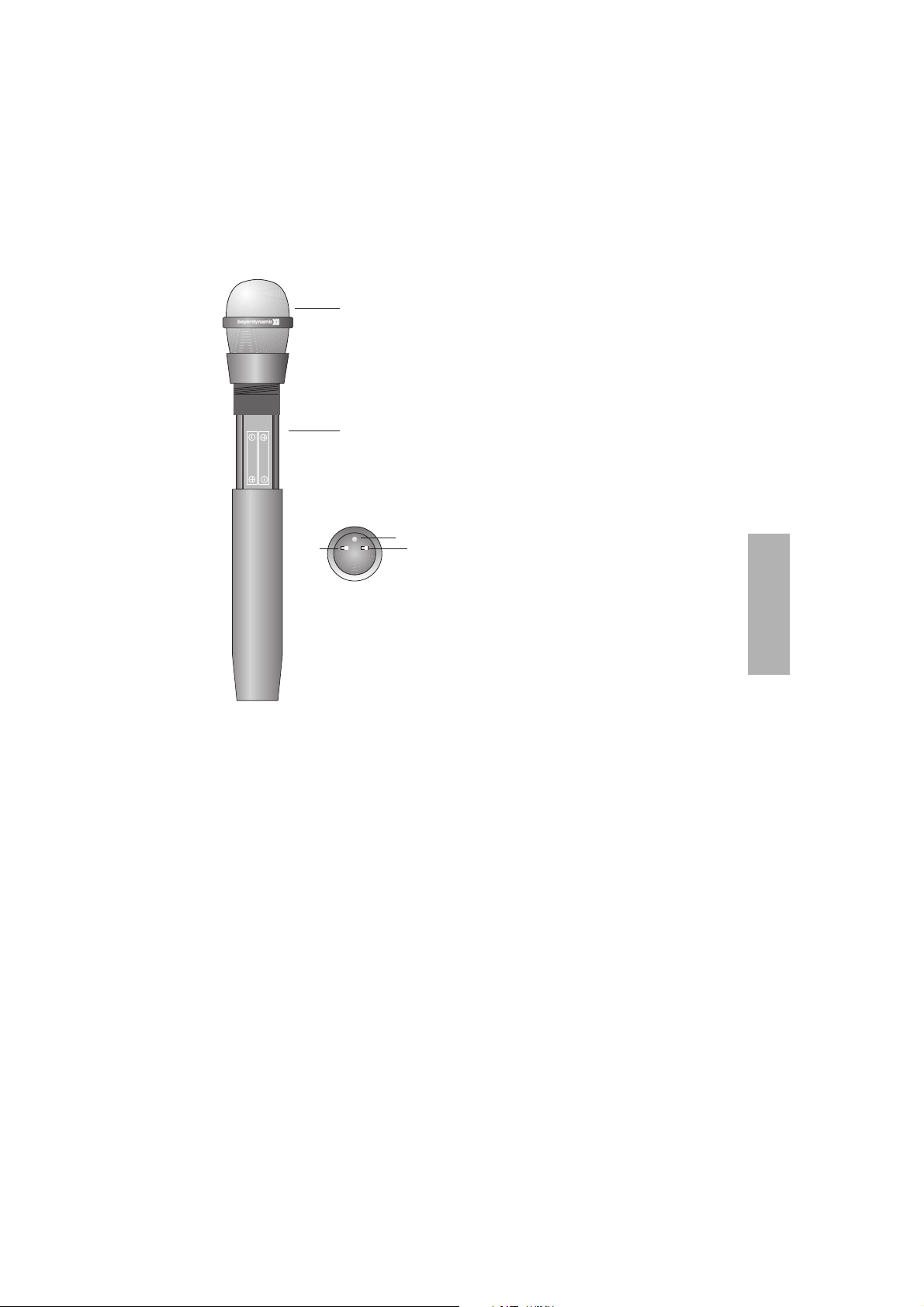
(1) Microphone head (fixed)
(2) Battery compartment
(3) Power On battery condition LED
(4) On/Off switch
(5) Mute switch
2.2 Setting up
1. Switch on the NE 100 receiver.
2. Rotate the microphone under the microphone head (1) counter clockwise and carefully
slide the transmitter shaft down. Insert two 1.5 V alkaline batteries (AAA type - micro).
Observe the polarity marks.
3. Slide the transmitter into the shaft again and rotate the microphone clockwise to lock.
4. Switch on the microphone by switching the On/Off switch (4) to the “On” position. The
Power On battery condition LED (3) is illuminated. If the transmitter is properly working
one of the diversity LEDs of the NE 100 receiver should be illuminated.
5. Make sure that the mute switch (5) is switched to the “Off” position. The mute switch (5)
is for muting the transmitter during pauses of speech. Please note that the microphone is
still consuming power when it is muted.
6. When the battery capacity is too low for operation, the power on battery condition LED (3)
will flash for around 1 hour before the transmitter switches off (LED (3) goes out).
english
19
(1)
(2)
ALKALINE
SIZE AAA
1.5 VOLTS
ALKALINE
SIZE AAA
1.5 VOLTS
(3)
(4)
On Off
Mute
On Off
Power
SEM 181
V
(5)
Page 6

20
7. To avoid popping, try holding the microphone at a slight angle below your mouth.
8. To avoid covering the integrated antenna by your hand, do not hold the microphone at
the microphone head as this could reduce the transmission strength. Furthermore, feedback
can occur.
2.3 Maintenance
Protect the microphone from humidity, knocks and shock. Avoid dropping the micro-
phone at all times.
If your microphone sounds dull, clean the integrated foam pop shield. To do this, follow the
instructions below.
• SDM 169: Unscrew the microphone upper basket counter clockwise.
SDM 159, SEM 181: Unscrew the whole microphone basket clockwise.
• Pull out the foam pop shield and clean it under clear running water. If necessary, use a mild
washing-up liquid. Dry it afterwards with a hairdryer or allow it to dry overnight.
• Place the dry pop shield inside the microphone basket and replace the microphone basket
by screwing it on clockwise or counter clockwise.
3. TS 100 Beltpack Transmitter
3.1 Controls and Indicators
(1) Mute switch
(2) red Peak LED (audio)
(3) Gain control (audio)
(4) Connection for microphones / instruments,
3.5 mm stereo jack (female), screw-type
(5) green Power On battery condition LED
(6) On / Off switch
(7) Antenna
(8) Battery compartment
3.2 Setting up
1. Open the battery compartment (8) by pulling the cover downwards. Insert a 9 V alkaline
battery or rechargeable battery observing the polarity +/- marks.
On
Mute
(1) (2) (3) (4) (5) (6)
Off
Peak
Vol Batt
On Off
Power
Opus
TS 100 V
VHF Transmitter
(7)
(8)
Page 7

english
21
2. Connect the supplied microphone or instrument cable to the jack socket (4).
3. Switch on the beltpack transmitter by switching the On / Off switch (6) to the “On” position.
The power on battery condition LED (5) is illuminated green when the battery has been
inserted correctly and has full capacity. If the transmitter is properly working, one of the
diversity LEDs of the NE 100 receiver should be illuminated.
4. Make sure that the mute switch (1) is switched to the “Off” position. The mute switch (1)
is for muting the transmitter during pauses of speech. Please note that the microphone is
still consuming power when it is muted.
5. When the battery capacity is too low for operation, the power on battery condition LED (5)
will flash for around 1 hour before the transmitter switches off (LED (5) goes out).
3.3 Adjusting Input Gain
1. Switch on the NE 100 diversity receiver.
2. Switch the transmitter on by switching the On / Off switch (6) to the “On” position. Turn
the gain control (3) to minimum sensitivity (fully counter clockwise).
3. If you have no suitable sound source, you can speak into the microphone at the maximum
level you expect to use. We recommend you choose a “U”, because a spoken “U” has a
relatively good sine-shape. Turn the gain control (3) clockwise until the peak LED (2) does
not illuminate or should only flash momentarily during the loudest passages.
Important:
There are various microphones available for the TS 100. As their characteristics vary, the sensitivity
has to be re-adjusted with each change of microphone.
4. General Instructions for all Transmitters
4.1 Battery Change
• Switch the transmitter off before changing the battery (On / Off switch to the “Off” position).
• If you do not intend to use the transmitter for several weeks or months, please remove the
battery as it can leak after some time and damage parts of the transmitter. Even “leak
proof” batteries are no guarantee that they will not leak after some time. Failing to
comply will render the warranty null and void.
• Different brands of batteries may vary in length of up to 2 - 3 mm. When you change the
battery make sure there is a good contact and adjust the spring in the battery compartment
if necessary.
• Clean the battery contacts from time to time. Use a soft cloth or cotton swab moistened
with methylated spirits or alcohol.
• Please do not throw used battery packs away with your household rubbish, but take them
to your local collection points.
• When using rechargeable batteries use conventional chargers.
Page 8

22
4.2 Before the Soundcheck
1. Make sure that the transmitter and receiver are on the same frequency (refer to type
plate).
2. Check the transmitter battery and replace or recharge it if necessary. Use fresh alkaline
batteries only.
3. Check the performance area for dropouts (i.e. areas where poor reception is encountered).
If you find any dropouts try to eliminate them by repositioning the antennae or the receiver.
4. Adjust the sensitivity of the receiver and beltpack transmitter correctly to avoid distortions.
5. Try and avoid feedback, especially when you use omnidirectional microphones (e.g. MCE 50).
4.3 What to do about Feedback
Feedback is caused when the microphone is too close to a loudspeaker.
We recommend:
• Reduce the volume of the sound system.
• Move away from the loudspeaker.
• Turn the microphone away from the loudspeaker.
• Use a microphone with a cardioid, hypercardioid or supercardioid polar pattern.
Caution:
Feedback can also be caused if the sensitivity has been adjusted too high. In this case the
transmitter is no longer working in the linear range, but in the limiter range. Therefore, if the
level of the input sound drops, the gain is increased and feedback can occur. Turning down the
input sensitivity of the transmitter to the correct position will prevent this from happening.
5. Trouble Shooting
5.1 NE 100 Diversity Receiver
•
Power supply is interrupted. Power supply
unit is not connected to the mains and/or
to the receiver
•
Connect the power supply unit to the
mains and/or to the receiver
•
Switch on the transmitter
• Make sure that the transmitter and
receiver are on the same frequency
• Position the receiving antennae
correctly
•
Input amplifier of the connected mixer is
overloaded
• Input sensitivity is too high (TS 100 only)
• Use the reduction of the mixer or
adjust the volume (5)
• Reduce sensitivity
Distorted sound
No reception
No function
Problem Possible Cause Solution
• Transmitter is not switched on
• Transmitter works on a different
frequency
•
Receiving antennae are not positioned
correctly
Page 9

english
23
• Transmitter and receiver have different
frequencies
• Insufficient battery voltage
•
Insufficient battery contact, battery
inserted incorrectly
• Make sure the transmitter and the
receiver are on the same frequency
• Replace the battery
•
Check the battery and insert it again
•
Transmission distance between transmitter
and receiver is too far
• Defective antenna (TS 100 only)
• Reduce the distance between
transmitter and receiver
• Check the antenna and replace it,
if necessary
No RF on the
receiver
No function
Problem Possible Cause Solution
5.2 SEM 181, SDM 159, SDM 169, TS 100 Transmitters
6. Maintenance
In the unlikely event of equipment failure, the product should be returned to your bey-
erdynamic dealer. Failure to do so will render the guarantee null and void.
7. Licensing
In most countries around the world, wireless systems must be approved for use by the
authorities and it may be necessary to obtain a licence to use it legally. Your local beyerdynamic
dealer will be able to give you details on wireless system regulations for your area.
The components of the Opus 100 system are approved according to the directive 99/5/EEC
under the CE 0682 ! identification.
•
Interference from other transmitters
• Two transmitters using the same frequency
• Battery of the transmitter is too weak
• Battery of the transmitter is too weak
• Switch off the other transmitters
• Avoid using two transmitters with the
same frequency
• Replace the battery
• Replace the battery
Noise/chirping
Power On battery
condition LED
Page 10

24
8. Versions
Opus 100 V Set consisting of:
NE 100 V VHF diversity receiver, TS 100 V VHF beltpack transmitter,
instrument cable and bag
Opus 150 V Set consisting of:
NE 100 V VHF diversity receiver, TS 100 V VHF beltpack transmitter,
MCE 60.100 clip-on microphone and bag
Opus 154 V Set consisting of:
NE 100 V VHF diversity receiver, TS 100 V VHF beltpack transmitter,
Opus 54.100 headset and bag
Opus 159 V Set consisting of:
NE 100 V VHF diversity receiver,
SDM 159 V VHF microphone and bag
Opus 169 V Set consisting of:
NE 100 V VHF diversity receiver,
SDM 169 V VHF microphone and bag
Opus 181 V Set consisting of:
NE 100 V VHF diversity receiver,
SEM 181 V VHF microphone and bag
The a.m. VHF sets are available with different frequencies.
Transmitters and receiver are also individually available.
Opus 100 U Set consisting of:
NE 100 U UHF diversity receiver, TS 100 U UHF beltpack transmitter,
instrument cable and bag
Opus 150 U Set consisting of:
NE 100 U UHF diversity receiver, TS 100 U UHF beltpack transmitter,
MCE 60.100 clip-on microphone and bag
Opus 154 U Set consisting of:
NE 100 U UHF diversity receiver, TS 100 U UHF beltpack transmitter,
Opus 54.100 headset and bag
Opus 159 U Set consisting of:
NE 100 U UHF diversity receiver,
SDM 159 U UHF microphone and bag
Opus 169 U Set consisting of:
NE 100 U UHF diversity receiver,
SDM 169 U UHF microphone and bag
Opus 181 U Set consisting of:
NE 100 U UHF diversity receiver,
SEM 181 U UHF microphone and bag
The a.m. UHF sets are available with different frequencies.
Transmitters and receiver are also individually available.
Page 11

english
25
9. Optional Accessories
NE 100 Diversity Receiver
19"-Option
ZTE 100/200 Shelf for 19"-rack mounting of one NE 100 receiver . . . . . . . Order # 457.051
SDM 159, SDM 169 and SEM 181 Microphones
Microphone clamp
MKV 11 Microphone clamp . . . . . . . . . . . . . . . . . . . . . . . . . . . . . . . . . Order # 407.232
Pop shields / Wind shields
PS 20/40 Pop shield for SDM 159, SDM 169, colour: charcoal-grey . . . Order # 437.972
PS 81* Pop shield for SEM 181, colour: charcoal-grey . . . . . . . . . . . . Order # 407.593
Stands
GST 400 Microphone stand, 3/8", height 0.90 - 1.65 m,
with G 400 boom . . . . . . . . . . . . . . . . . . . . . . . . . . . . . . . . . . Order # 421.294
GST 500 Microphone stand, 3/8", height 0.80 - 1.60 m,
with G 500 telescopic boom . . . . . . . . . . . . . . . . . . . . . . . . . . Order # 406.252
*other colours available
10. Technical Specifications
NE 100 V / NE 100 U Diversity Receiver
Frequency range
NE 100 V (VHF). . . . . . . . . . . . . . . 1 frequency between 174 - 236 MHz
NE 100 U (UHF) . . . . . . . . . . . . . . 1 frequency between 798 - 862 MHz
Nominal deviation . . . . . . . . . . . . 35 kHz
Frequency response . . . . . . . . . . . 50 - 15,000 Hz
T.H.D. . . . . . . . . . . . . . . . . . . . . . . < 1% (30 kHz) (transmitter and receiver)
Noise reduction . . . . . . . . . . . . . . LN compander
S/N ratio
at RF-level 70 dBm . . . . . . . . . . . . > 100 dB(A)
at RF-level 85 dBm . . . . . . . . . . . . > 90 dB(A)
RF-bandwidth. . . . . . . . . . . . . . . . < 200 kHz
Audio output . . . . . . . . . . . . . . . . 3-pin XLR, balanced
Temperature range . . . . . . . . . . . +10° to 55°C
Power supply . . . . . . . . . . . . . . . . external Power Supply Unit (11 - 15 V, 200 mA) DC/AC
Dimensions (W x H x D) . . . . . . . . 226 x 39 x 115 mm
Weight . . . . . . . . . . . . . . . . . . . . . 650 g
Page 12

26
SDM 159 V / U, SDM 169 V / U and SEM 181 V / U Microphones
Polar pattern . . . . . . . . . . . . . . . . Supercardioid (SDM 169) / Supercardioid (SDM 159)
Cardioid (SEM 181)
Transducer type . . . . . . . . . . . . . . Dynamic (SDM 159, SDM 169) /
electret condenser (SEM 181)
Frequency
SDM 159 V / SDM 169 V /
SEM 181 V (VHF) . . . . . . . . . . . . . 1 frequency between 174 - 236 MHz
SDM 159 U / SDM 169 U /
SEM 181 U (UHF) . . . . . . . . . . . . . 1 frequency between 798 - 862 MHz
RF output power . . . . . . . . . . . . . < 20 mW (output power)
Nominal deviation . . . . . . . . . . . . 35 kHz
Frequency response . . . . . . . . . . . 50 - 15,000 Hz
Noise reduction . . . . . . . . . . . . . . LN compander
S/N ratio at RF level 70 dBm. . . . . > 100 dB(A)
Sensitivity . . . . . . . . . . . . . . . . . . . fixed
Max. SPL. . . . . . . . . . . . . . . . . . . . 130 dB
Temperature range . . . . . . . . . . . +10° to 55°C
Antenna . . . . . . . . . . . . . . . . . . . . integrated in housing
Power supply . . . . . . . . . . . . . . . . 2 x 1.5 V alkaline batteries (AAA type “micro”)
Current consumption . . . . . . . . . . 130 mA (UHF), 100 mA (VHF)
Operating time . . . . . . . . . . . . . . > 5 hrs. with alkaline batteries
TS 100 V / TS 100 U Beltpack Transmitters
Frequency
TS 100 V (VHF) . . . . . . . . . . . . . . . 1 frequency between 174 - 236 MHz
TS 100 U (UHF) . . . . . . . . . . . . . . . 1 frequency between 798 - 862 MHz
RF output power . . . . . . . . . . . . . < 20 mW (output power)
Nominal deviation . . . . . . . . . . . . 35 kHz
Frequency response . . . . . . . . . . . 50 - 15,000 Hz
Noise reduction . . . . . . . . . . . . . . LN compander
S/N ratio at RF level 70 dBm. . . . . > 100 dB(A)
Sensitivity . . . . . . . . . . . . . . . . . . . adjustable, 40 mV - 1 V
Audio input . . . . . . . . . . . . . . . . . 3.5 mm jack locking (female), 3-pole, screw-type
Power supply . . . . . . . . . . . . . . . . 9 V alkaline battery or corresponding NiMH-rechargeable
battery
Current consumption
TS 100 U (UHF) . . . . . . . . . . . . . . . 65 mA
TS 100 V (VHF) . . . . . . . . . . . . . . . 50 mA
Temperature range . . . . . . . . . . . +10° to 55°C
Operating time
with 9 V alkaline battery
TS 100 U (UHF) . . . . . . . . . . . . . . . > 6 hrs.
TS 100 V (VHF) . . . . . . . . . . . . . . . > 8 hrs.
Page 13

english
27
 Loading...