

Page 1
Operating Instructions
Non-contractual illustrations. Subject to change without notice.
AS101101
AT 91
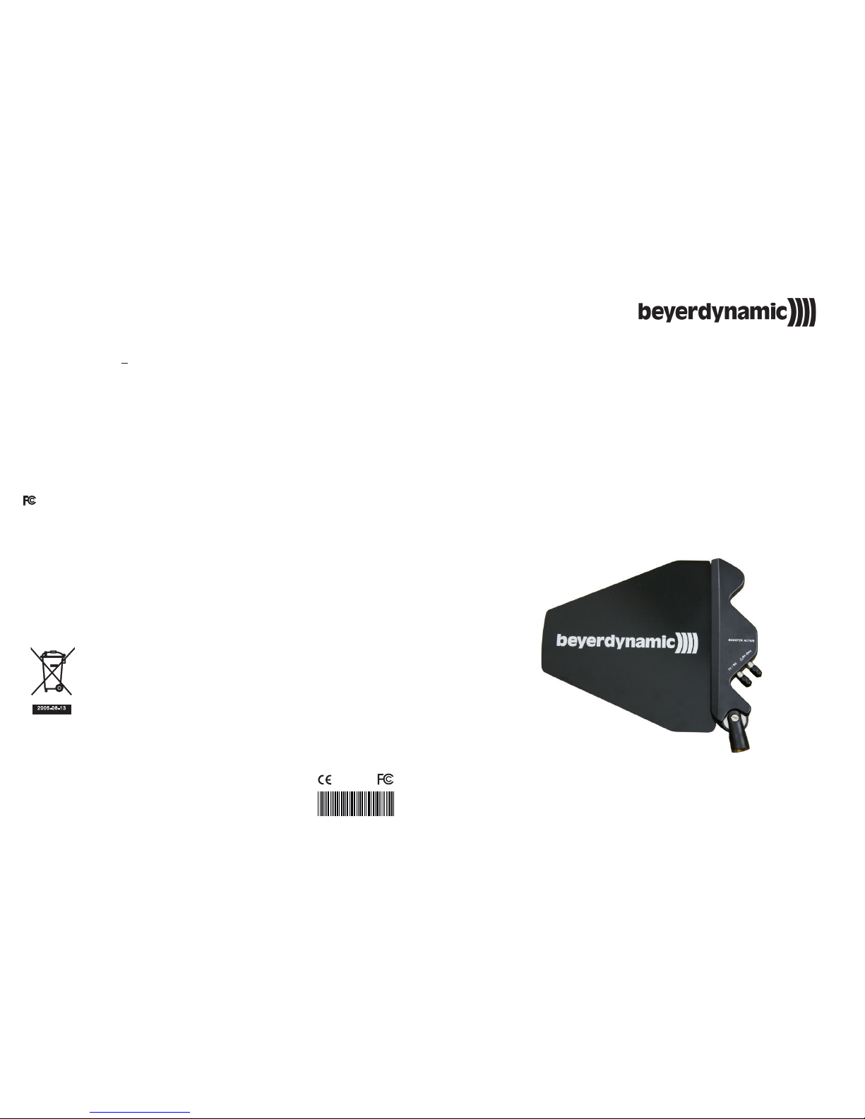
UHF Directional Antenna
2CE3 95 A
Technical Specifications
!
!
!
!
!
!
!
!
!
≦ ≦
Bandwidth:
Gain:
Amplifier gain:
VSWR (Voltage Standing Wave Ratio):
3 dB beam width:
Power consumption:
Connector:
Dimensions:
Weight:
480 MHz to 1000 MHz
4-6 dBi
12 1 dB (RX connector), 0 dB (RX/TX connector)
2 1 (RX connector), 2 1 (RX/TX connector)
75 vertical and 130 horizontal
1120 mW (RX connector), 0 mW (RX/TX connector)
TNC socket
319 270 25 mm
430 g
+
: :
° °
× ×
& IC - ID
THIS DEVICE COMPLIES WITH PART 15 OF THE FCC RULES AND RSS-123 ISSUE2 OF
CANADA. OPERATION IS SUBJECT TO THE FOLLOWING TWO CONDITIONS:
(1) This device may not cause interference.
(2) This device must accept any interference, including inteference that may cause
undesired operation of the device. This equipment complies with FCC RF radiation
exposure limits set forth for an uncontrolled environment.
Disposal
2005 -08-1 3
Never dispose used batteries with domestic waste.
Batteries / NiCad cells often contain heavy metals such as cadmium
(Cd), mercury (Hg) and lead (Pb) that makes them unsuitable for
disposal with domestic waste. You may return used
batteries/rechargeable batteries free of charge to local collection
points or recycling centres.
By doing so, you contribute to the conversation of the environment!
beyerdynamic GmbH & Co. KG
Theresienstr. 8 | 74072 Heilbronn | Germany
Tel.: +49 (0)7131 / 617-440 | Fax: +49 (0)7131 / 617-204
info@beyerdynamic.de | www.beyerdynamic.com
Page 2
!
!
!
When using the RX connector , please note that the inner wire of the antenna cable
does not touch the case itself. As the connector is provided with 8V DC, a short circuit
could occur.
The RX connection can only be connected to receivers and not to transmitters. When
connecting to transmitters, the transmitter can be damaged.
The shorter the length of the coaxial cable to connect the TX/RX connector to a
receiver, the better. The cable length should not exceed 20 m, otherwise the signal
strength could decrease too much. The coaxial cable, however, which is connected to
the RX connector should be longer than 20 m, otherwise the integrated booster
could cause an over-gain and therefore a signal saturation, which can result in a
deterioration of the anti-interference feature. The sensitivity will be improved by using
the RX connector , but the anti-interference feature may deteriorate.
The 2-way AT 91 directional antenna operates in the UHF range between 480 MHz and
1000 MHz. It can be used as a receiving or transmitting antenna. The antenna is
provided with an integrated booster for longer distances. The booster is powered via
coaxial cables that are connected to antenna splitters or receivers with TNC connector.
The AT 91 is ideal for both indoor and outdoor applications.
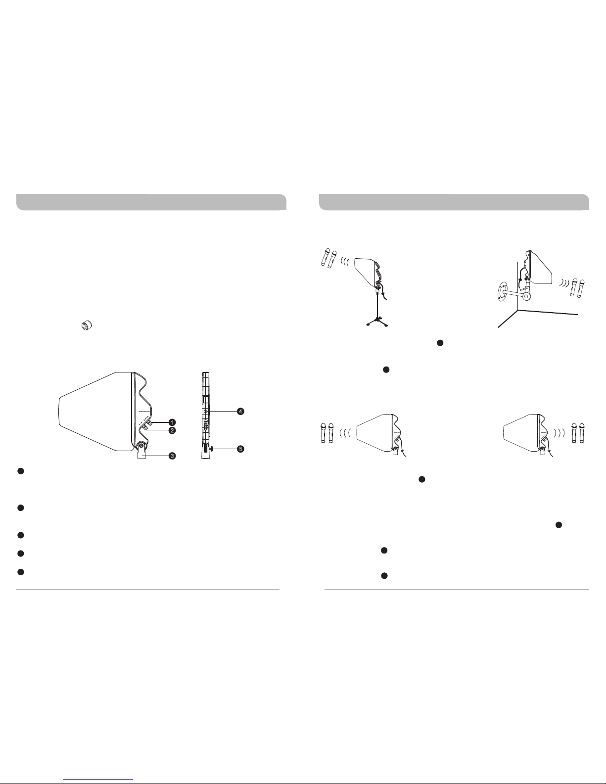
RX antenna cable connector:
TX/RX antenna cable connector:
Swivel adapter bracket:
Power LED:
Holding screw:
The connector is provided with an integrated 12dB
booster, which is necessary when the antenna cable length exceeds 20 metres and
when the antenna is connected to a receiver or antenna splitter with an output power
of 8V DC.
Transmission output or antenna input, 0 dB, can
be connected to transmitters or receivers by using a cable with a maximum length of
20 m.
Can be mounted on a tripod or can be used with the
MS-50 wall-mounting kit.
The LED will illuminate at a power input of 8V DC from receivers. At the
same time the booster will start to operate.
To hold the antenna‘s direction. Loosen the screw to adjust the
direction of the antenna and tighten again to hold in new position.
!
!
!
The TX/RX antenna cable connector can be connected to transmitters, receivers,
antenna combiners and antenna splitters with TNC socket by using an antenna cable
with a maximum length of 20 metres.
The RX connector can be connected to a receiver or antenna splitter by using an
antenna cable longer than 20 metres. After switching on, please check the power LED
of the antenna. If the LED is not illuminated, the integrated booster does not operate.
In order to achieve best results, adjust the antenna to a proper position.
! Place the antenna onto a tripod or on top of the MS-50 wall-mounting kit and tighten
the screw as shown in the illustrations below.
Supplied Accessories
1. 1 x 3/8" adapter (for standard tripods)
2.
1 x manual
Controls and Indicators
Installation
(Mounting on the MS-50 wall-mounting kit)
(Figure 3)
(Mounting on a tripod)
(Figure 2)
( 4: Correct installation)○Figure
(Figure 5: Wrong installation)×
Notes
1
2
1
2
2
2
1
1
1
1
3
4
5
(Figure 1 )
1
2
3
5
4
AT 91 UHF Directional Antenna AT 91 UHF Directional Antenna
 Loading...