

Page 1

AD 808
4-Kanal Aktiv-Antennencombiner
4-Channel Active Antenna Combiner
BEDIENUNGSANLEITUNG
OPERATING INSTRUCTIONS
Page 2

Page 3

3
INHALT / CONTENTS
BEDIENUNGSANLEITUNG AD 808
OPERATING INSTRUCTIONS AD 808
english deutsch
Lieferzubehör . . . . . . . . . . . . . . . . . . . . . . . . . . . . . . . Seite 4
Anwendung . . . . . . . . . . . . . . . . . . . . . . . . . . . . . . . . Seite 4
Technische Daten . . . . . . . . . . . . . . . . . . . . . . . . . . . . Seite 4
Bedienelemente . . . . . . . . . . . . . . . . . . . . . . . . . . . . . Seite 4
Installation . . . . . . . . . . . . . . . . . . . . . . . . . . . . . . . . . Seite 5
Wichtiger Hinweis . . . . . . . . . . . . . . . . . . . . . . . . . . . . Seite 6
Entsorgung . . . . . . . . . . . . . . . . . . . . . . . . . . . . . . . . . Seite 6
Supplied Accessories . . . . . . . . . . . . . . . . . . . . . . . . . . Page 8
Application . . . . . . . . . . . . . . . . . . . . . . . . . . . . . . . . . Page 8
Technical Specifications . . . . . . . . . . . . . . . . . . . . . . . . Page 8
Controls and Indicators . . . . . . . . . . . . . . . . . . . . . . . . Page 8
Installation . . . . . . . . . . . . . . . . . . . . . . . . . . . . . . . . . Page 9
Important Note . . . . . . . . . . . . . . . . . . . . . . . . . . . . . . Page 10
Disposal . . . . . . . . . . . . . . . . . . . . . . . . . . . . . . . . . . . Page 10
Page 4
4
Sie haben sich für den Antennencombiner AD 808 entschieden. Vielen Dank für Ihr Vertrauen.
Nehmen Sie sich bitte einige Minuten Zeit und lesen Sie diese Bedienungsanleitung vor
Inbetriebnahme aufmerksam durch.
Lieferzubehör
1 x Bedienungsanleitung
Technische Daten
1. Bandbreite: 600 - 900 MHz
2. Kanäle: bis zu 4 Sender
3. Anzeige: für Eingangssignal, leuchtet bei > +6 dBm
4. Max. Eingangsleistung: +20 dBm (100 mW). Ideale Intermodulationseigenschaften.
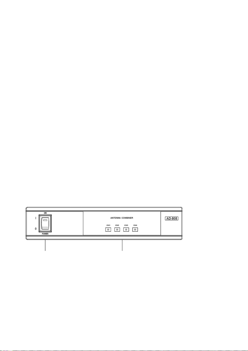
Ein-/Ausschalter. Leuchtet, wenn das Gerät eingeschaltet ist.
Anzeige für Eingangssignal: Wenn das Eingangssignal > +6 dBm ist, leuchtet die LED.
1. Bedienelemente
Anwendung
Der AD 808 ist ein 4-Kanal Aktiv-Antennencombiner, der im UHF-Frequenzbereich zwischen 600
und 900 MHz arbeitet. Der Antennencombiner dient zum Aufsummieren der Sendesignale von bis zu
4 Sendern auf eine Antenne bei professionellen Mehrkanalanwendungen.
Vorderseite
Page 5
5
2. Installation
2.1 Installation des Eingangssignals
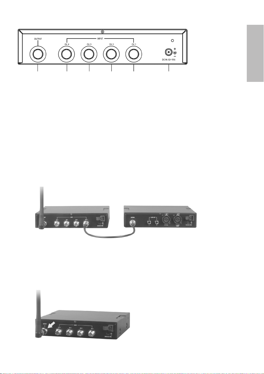
Verbinden Sie den Antennenausgang des Senders mit dem jeweiligen Antenneneingang des Antennencombiners über ein Koaxialkabel mit TNC-Anschluss. Für einen optimalen Empfang sollte das Koaxialkabel so kurz wie möglich sein. An den Antennencombiner können bis zu 4 Sender angeschlossen
werden.
2.2 Antennenanschluss
Für eine optimale Übertragung sollte die an den Combiner angeschlossene Antenne im gleichen
Frequenzbereich arbeiten, wie die Senderantenne.
Antennenausgang zum Anschluss der Antenne
Eingänge zum Anschluss von maximal 4 Sendern
DC-Anschluss für 12 - 15 V DC-Netzteil
Rückseite
AD 808 Sender
deutsch
Page 6
6
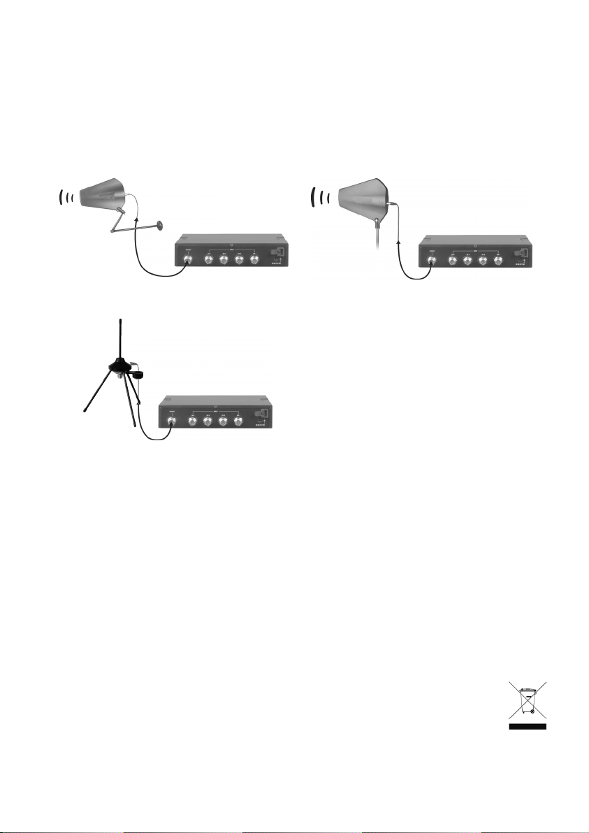
2.3 Anschluss abgesetzter Antennen
Zur Installation abgesetzter Antenne können Sie die AT 70 oder AT 90 T verwenden. Beide Antennen
können an der Wand mit der Wandbefestigung MS 10 oder auf einem normalen Mikrofonstativ
montiert werden. Zum Anschluss empfehlen wir hochwertige Koaxialkabel, die so kurz wie möglich
sein sollten. Bei der Installation der Antennen sollten Sie darauf
achten, dass die Antennen über der Zuschauermenge angeordnet werden und dass keine Hindernisse
den Empfang beeinträchtigen.
3. Wichtiger Hinweis
Der Combiner arbeitet im Frequenzbereich zwischen 600 und 900 MHz. Er funktioniert mit jedem
Sender in diesem Bereich. Für eine optimale Übertragung sollte die Sendeantenne dem Frequenzbereich des Senders entsprechen. Zum Anschluss an den Combiner AD 808 empfehlen wir die Antenne
AT 90 T oder AT 70. Zum Anschluss sollten Sie ein 50 Ohm-Koaxialkabel verwenden, das möglichst
nicht länger als 10 Meter ist.
AT 90 T
MS 10
Abgesetzte Antenne mit Wandbefestigung Abgesetzte Antenne auf Stativ befestigt
Abgesetzte Antenne auf Stativ befestigt
AT 70
4. Entsorgung
Dieses Produkt darf am Ende seiner Lebensdauer nicht über den normalen Haushaltsabfall
entsorgt werden, sondern muss an einem Sammelpunkt für das Recycling von elektrischen
und elektronischen Geräten abgegeben werden. Das Symbol auf dem Produkt, der
Gebrauchsanweisung oder der Verpackung weist darauf hin.
Page 7

Page 8

8
Thank you for selecting the AD 808 antenna combiner system.
Please take some time to read carefully through this manual before setting up the equipment.
Supplied Accessories
1 x Manual
Technical Specifications
1. Bandwidth: 600 - 900 MHz
2. Channels: up to four transmitters
3. Indicator: will illuminate when input signal is > +6 dBm
4. Max. input power: +20 dBm (100 mW). Ideal intermodulation characteristic.
Power On/Off switch. LED will illuminate when power is on.
LED for Input Signal. The LED will illuminate, when the input signal is > +6 dBm.
1. Controls and Indicators
Application
The AD 808 is a 4-channel active antenna combiner operating in the frequency range from 600 to
900 MHz. Up to four wireless transmitters can be combined into one transmitting antenna for
professional multi-channel applications.
Front view
Page 9
9
2. Installation
2.1 Installation of the input signal
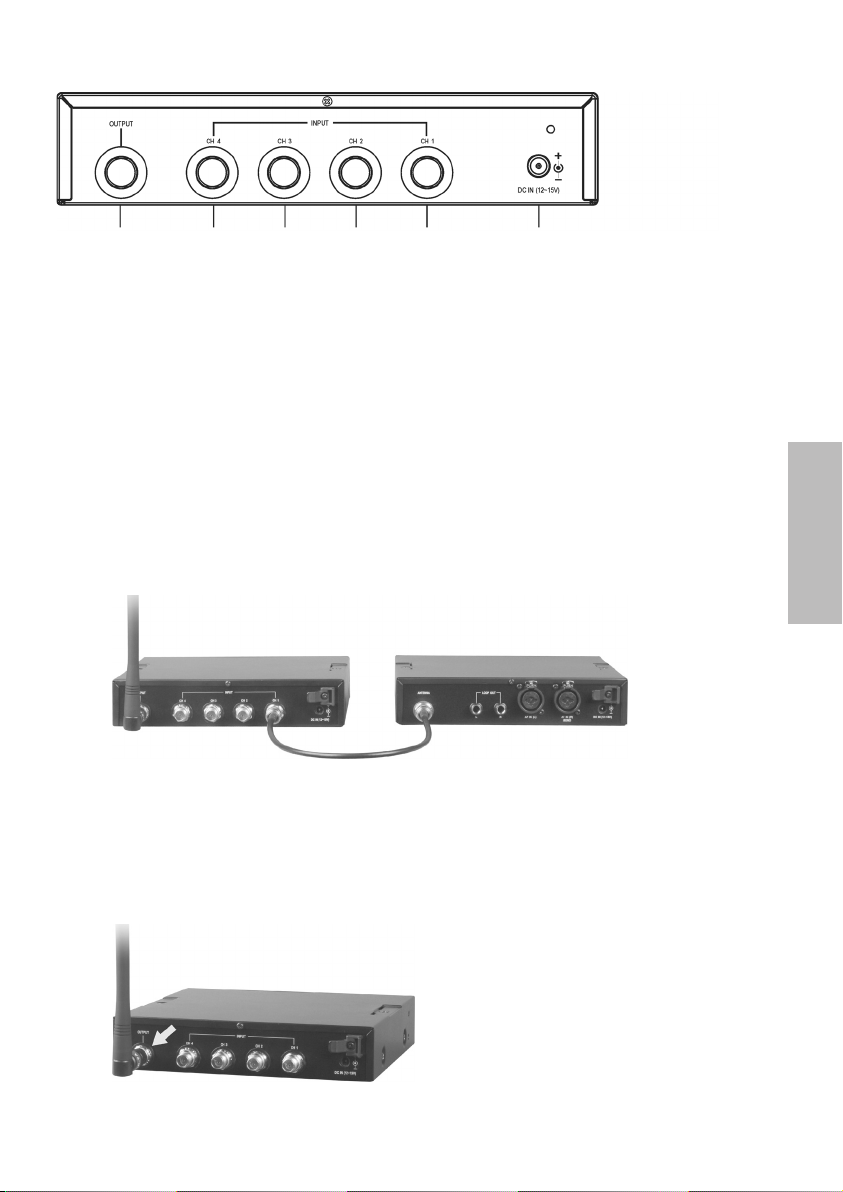
Use coaxial cables with TNC connectors to connect the outputs of the transmitters to the inputs of the
AD 808 combiner. Make sure that the coaxial cables are as short as possible for optimum operation.
Up to four transmitters can be connected to the antenna combiner.
2.2 Antenna installation
For optimal transmission the antenna connected to the combiner should operate in the same
frequency band as the transmitter antenna.
Antenna output to connect the antenna
Inputs to connect a maxiumum of 4 transmitters
DC power input jack to connect 12 - 15 V AC/DC adapter
Rear view
AD 808 Transmitter
english
Page 10

10
2.3 Installation of remote antennas
To install remote antennas use the AT 70 or AT 90 T. Both antennas can be mounted to the wall by
using the MS 10 wall mount bracket or onto a standard microphone stand. For connecting use high
quality coaxial cables which should be as short as possible. For optimal reception make sure that the
antenna is positioned above the audience and away from obstacles.
3. Important Note
The combiner operates in the frequency range between 600 and 900 MHz. It works with any transmitter
within this range. For optimal transmission make sure that the transmitting antenna operates in the
same frequency band as the transmitter. We recommend using the AT 90 T or AT 70 antenna to
connect to the AD 808 combiner. For connecting use 50 ohms coaxial cables which are not longer than
10 metres.
AT 90 T
MS 10
Remote antenna with wall mount bracket Remote antenna mounted onto a stand
Remote antenna mounted onto a stand
AT 70
4. Disposal
This symbol on the product, in the instructions or on the packaging means that your electrical
and electronic equipment should be disposed at the end of its life separately from your
household waste. There are separate collection systems for recycling in the EU. For more
information, please contact the local authority or your retailer where you purchased the
product.
Page 11

Page 12

DE2/BA AD 808 (01.09)/ • Abbildungen nicht vertragsbindend. Änderungen und Irrtümer vorbehalten • Non-contractual illustrations. Subject to change without notice.
beyerdynamic GmbH & Co. KG
Theresienstr. 8 | 74072 Heilbronn – Germany
Tel. +49 (0) 7131 / 617 - 0 | Fax +49 (0) 7131 / 617 - 224
info@beyerdynamic.de | www.beyerdynamic.de
Weitere Vertriebspartner weltweit finden Sie unter www.beyerdynamic.de
For further distributors worldwide, please go to www.beyerdynamic.com
 Loading...