

Bewator Visilynx 3 User Manual

Visilynx 3 Series Matrix Switcher
VisiPC Software Version 2.01
Part 1 – Visilynx 3 Configurator
USER MANUAL
Manual : INS00231 Issue 4

VisiPC Software Manual Part 1 – Visilynx 3 Configurator
INS00231 Issue 4 Page 2 of 88
Table Of Contents
1 INTRODUCTION
................................
................................
................................
.............................
3
1.1 P
RINCIPLES OF OPERATION
................................
................................
................................
...........
4
2 GETTING STARTED
................................
................................
................................
......................
5
2.1 H
ARDWARE INTERCONNECTION
– RS232 I
NTERFACE
................................
................................
.....
5
2.2 M
INIMUM
PC R
EQUIREMENTS
................................
................................
................................
........
6
2.3 S
OFTWARE INSTALLATION
................................
................................
................................
..............
6
2.4 S
OFTWARE START-UP
................................
................................
................................
...................
6
3 MENU BAR
................................
................................
................................
................................
.....
9
3.1 F
ILE MENU COMMANDS
................................
................................
................................
.................
9
3.2 N
ODE MENU COMMANDS
................................
................................
................................
.............
13
3.3 T
RANSFER MENU COMMANDS
................................
................................
................................
......
13
3.4 S
WITCH MENU COMMANDS
................................
................................
................................
..........
17
3.5 O
PTIONS MENU COMMANDS
................................
................................
................................
........
18
3.6 H
ELP MENU COMMANDS
................................
................................
................................
..............
20
4 SYSTEM SETTINGS
................................
................................
................................
....................
21
4.1 I
NTRODUCTION
................................
................................
................................
............................
21
4.2 S
HORTCUT KEYS
................................
................................
................................
........................
21
4.3 G
LOBAL SYSTEM SETTINGS
................................
................................
................................
.........
22
4.4 A
LARM SETTINGS
................................
................................
................................
........................
24
4.5 C
AMERA SETTINGS
................................
................................
................................
.....................
27
4.6 C
OMMUNICATION CHANNEL SETTINGS
................................
................................
.........................
31
4.7 K
EYBOARD SETTINGS
................................
................................
................................
..................
33
4.8 M
ONITOR SETTINGS
................................
................................
................................
....................
39
4.9 M
ULTIPLEXER SETTINGS
................................
................................
................................
..............
48
4.10 N
ODE SETTINGS
................................
................................
................................
.....................
50
4.11 N
ODE TRUNK SETTINGS
................................
................................
................................
..........
53
4.12 Q
UAD CARD SETTINGS
................................
................................
................................
...........
54
4.13 R
ELAY SETTINGS
................................
................................
................................
....................
58
4.14 S
EQUENCE SETTINGS
................................
................................
................................
.............
60
4.15 S
YSTEM SETTINGS
................................
................................
................................
..................
62
4.16 T
ELEMETRY CARD SETTINGS
................................
................................
................................
...
65
4.17 T
IMED EVENT SETTINGS
................................
................................
................................
..........
69
4.18 U
SER SETTINGS
................................
................................
................................
.....................
71
4.19 VCR/DVR S
ETTINGS
................................
................................
................................
.............
79
4.20 V
IEW SETTINGS
................................
................................
................................
......................
82
4.21 Z
ONE SETTINGS
................................
................................
................................
.....................
83
5 VISILYNX 3 TESTER & SIMULATOR
................................
................................
..........................
85
6 RECEIVER TESTER & SIMULATOR
................................
................................
...........................
86
7 RECEIVER CONFIGURATOR
................................
................................
................................
.....
87
8 NOTES
................................
................................
................................
................................
..........
88

VisiPC Software Manual Part 1 – Visilynx 3 Configurator
INS00231 Issue 4 Page 3 of 88
1 INTRODUCTION
Visilynx 3 Integrated (V3i) is a 32 loop-through input by 8 output full cross-point video matrix
node contained in a 19” wide by 3U high unit. A pair of V3i units can be linked via an
expansion cable, in a master/slave configuration, to provide a system with 64 camera inputs,
16 monitor outputs and 256 alarm inputs.
Visilynx 3 Modular (V3M) is a modular CCTV system designed to provide up to 32 users with
control of up to 511 fully functional cameras. A smaller special-purpose rack system is used
for trainborne applications.
All Visilynx 3 series matrix switcher systems are supplied with a CD-ROM package of
configuration and test software called VisiPC, which should be installed onto a suitable PC.
VisiPC runs under the industry standard Microsoft Windows 95, 98, 2000 and NT operating
systems. It is both user friendly, and comprehensive, and forms the heart of the systems
configuration and test capability.
The User Manual for VisiPC software is provided in two parts:
a) Part 1 (this document) is for the ‘Visilynx 3 Configurator’ sub-program.
b) Part 2 (Bewator Limited document INS00237) describes the ‘Visilynx 3 Tester &
Simulator’ sub-program.
The VisiPC Visilynx 3 Configurator sub-program includes features to aid the creation and
adjustment of ‘Configuration Files’ (.V3) for an installed Visilynx 3 system.
The VisiPC Visilynx 3 Tester & Simulator sub-program includes features for the functional
testing of Visilynx 3 systems.
The VisiPC software also includes additional features for use with the RX3 receiver to aid:
a) Upgrading the software.
b) Functional testing.
These operations are detailed in the RX3 Receiver Installation and Maintenance Manual
(Bewator Ltd. Document INS00271) and are therefore not included in this document.
VisiPC Software Manual Part 1 – Visilynx 3 Configurator
INS00231 Issue 4 Page 4 of 88
1.1 Principles Of Operation
VisiPC's main principles of operation are:
•
A PC COM port is chosen at the ‘Options/Comm. Port’ menu.
•
The PC port is connected to the Visilynx 3 system ‘test and config’ port using an RS-232
cable.
•
Existing configuration is fetched from the system using the ‘Comms’ menu or a toolbar
button, or loaded from a disk file using the ‘File’ menu (configuration file extension is .V3).
•
Configuration is edited using the ‘Communications Settings’ and ‘Global System Settings’
displays.
•
The configuration is saved to a disk file at the ‘File’ menu or a toolbar button.
•
The configuration is sent to the system using the ‘Comms’ menu or a toolbar button.
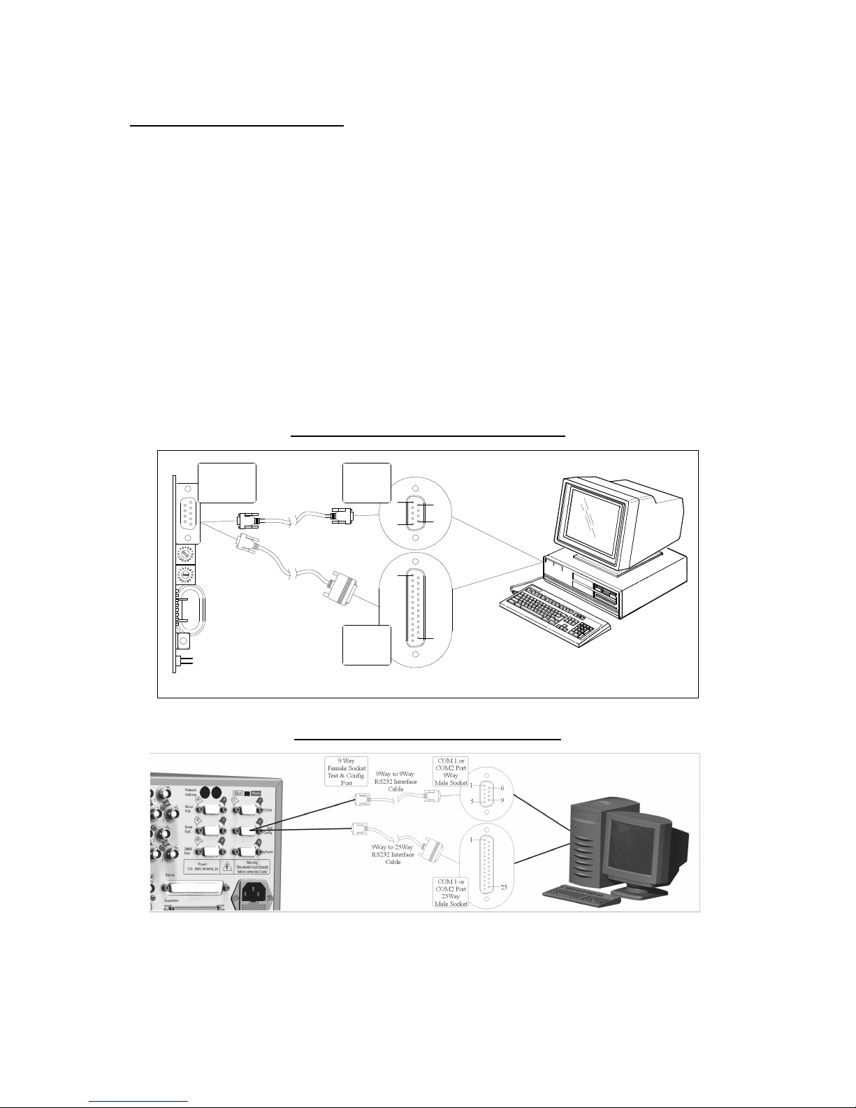
•
The diagrams below show the installation requirements for the Visilynx 3 system
configuration set-up.
Figure 1 V3M Installation Requirements
COM 1 or
COM2 Port
9Way
Male Socket
1569125COM 1 or
COM2 Port
25Way
Male Socket
Personal
Computer
(PC)
9 Way
Female Socket
Test & Config.
Port
9Way to 9Way
RS232 Interface
Cable
9Way to 25Way
RS232 Interface
Cable
CPU
Card
Figure 2 V3i Installation Requirements

VisiPC Software Manual Part 1 – Visilynx 3 Configurator
INS00231 Issue 4 Page 5 of 88
2 GETTING STARTED
2.1 Hardware Interconnection – RS232 Interface
2.1.1 Visilynx 3 Modular (V3M)
The V3M ‘T226-E’ CPU card incorporates an RS232 ‘test and config’ port which allows
Visilynx 3 Modular to be connected, via a 9-way to 9-way interface lead, to an external PC for
system set-up and testing. Please refer to Figure 1.
2.1.2 Visilynx 3 Integrated (V3i)
The V3i System Unit incorporates an RS232 Test/Config connector port on the rear panel
which allows connection, via a supplied 9-way to 9-way interface lead (Bewator Ltd. Part
Number VC-3CONFIG), to an external PC for system set-up and testing. Please refer to
Figure 2.
2.1.3 Interface Lead
If the serial port on your PC is a 25-way connection, you will need to purchase a suitable 9way to 25-way ‘D’ type pre-wired interface lead to connect to V3 system. (V3 trainborne
racks use a special cable to connect the PC to the rack PTE port.)
Tables 1 and 2, shown below, are for reference and give details of the pin-outs used for
RS232 transmission.
Note that the 25 to 9-way option is wired differently to the 9-way to 9-way cable. If
attempting to manufacture this lead, these pin-outs must be observed.
Table 1 Cable Wiring for 9-Way PC COM Port
PC V3 Test/Config Port
9-Way ‘D’ Female 9-Way ‘D’ Male
2 2
3 3
5 5
Table 2 Cable Wiring for 25-Way PC COM Port
PC V3 Test/Config Port
25-Way ‘D’ Female 9-Way ‘D’ Male
2 3
3 2
7 5

VisiPC Software Manual Part 1 – Visilynx 3 Configurator
INS00231 Issue 4 Page 6 of 88
2.2 Minimum PC Requirements
•
Windows 95, 98, NT, 2000, XP
•
64Mb RAM
•
Pentium 233MHz
•
One serial port
•
10Mb of hard disk space
•
CD-ROM drive
Warning:
If the PC is slower than listed above, or if it is fitted with a network card that is not
connected to a live network, then communications errors may occur when transferring new
software to a Visilynx 3 system.
2.3 Software Installation
1. Insert the CD-ROM containing VisiPC into your CD drive.
2. Windows 95, 98, 2000 or NT should all automatically run the installation set-up
procedure.
3. If your CD drive is not set to auto-run’ you will need to run the software installation from
within ‘
My Computer
’. Simply right-click on the CD drive and select
Auto Play
.
4. If that option is not available, run the
Setup.exe
program on the CD.
5. The installation program will install VisiPC into the default folder
C:\Program
Files\VisiPC
, but you may choose a different folder if you prefer.
6. Once the installation procedure is finished, Windows may prompt you to restart your PC
to complete the installation.
7. If you want to create a desktop shortcut, right-click on the
Start
button and choose
‘Explore’. Navigate down to
Programs/VisiPC
. Right-click and select ‘Copy’. Go the
desktop and right-click. Select 'Paste' to create the shortcut.
8. Following installation, this CD must be stored in a safe place as a backup in the unlikely
event that the software becomes corrupted.
2.4 Software Start-Up
Three methods can be used to run the software. Either:
•
Double click on your newly created shortcut (by far the quickest method).
•
Use the
Start
menu to view the
Programs
menu, where
VisiPC
can be found.
•
Use the
Run…
command in the
Start
menu and
Browse…
through the program files on
your C: drive. When you find
VisiPC.exe
click on
Open
and then click on OK in the Run
window, as shown below.
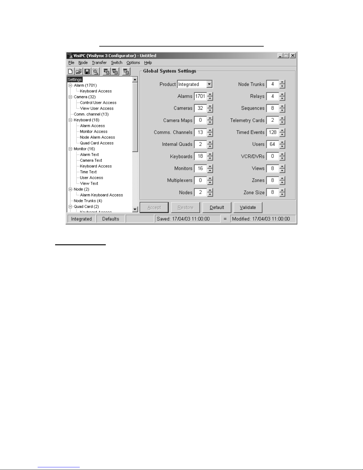
The first screen visible when running the software for the first time is the VisiPC (Visilynx 3
Configurator) ‘Global System Settings’ screen, shown in Figure 3.
On all subsequent uses, the VisiPC program starts up in the sub-program in which it was
shut down.
VisiPC Software Manual Part 1 – Visilynx 3 Configurator
INS00231 Issue 4 Page 7 of 88
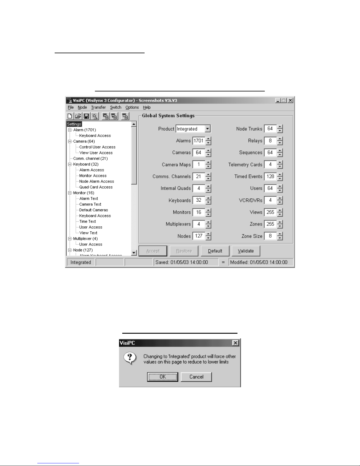
Figure 3 Visilynx 3 Configurator Global System Settings
2.4.1 Status Bar
A status bar along the bottom of the screen displays various information on the configuration
or communication status in five panes.
The leftmost pane indicates the selected product, either ‘Modular’ or ‘Integrated’.
The second pane indicates either:
a) ‘Changed’ i.e. configuration has been changed by pressing the
Accept
button and has
not yet been saved, or
b) ‘Defaults’ i.e. File/New has been selected and no changes have been made on any
screen.
The third pane indicates whether the configuration data is ‘Invalid’ i.e. contains errors. If this
is indicated, the configuration cannot be sent to the Visilynx 3 system.
The fourth pane indicates the date and time when the file was last saved to disk by VisiPC.
The fifth pane indicates the date and time when either:
a) the file was modified by the V3 system e.g. keyboard. This is shown for a file received
from a Visilynx 3 system and not modified since by VisiPC, or
b) the most recent time that the
Accept
button was pressed to accept changes on a screen.
The sign between the fourth and fifth panes highlights that the ‘Saved’ and ‘Modified’ dates
are the same (‘=’) or are different (‘<>’) and acts as a reminder that the configuration
received from the Visilynx 3 system should be saved (see page 13).

VisiPC Software Manual Part 1 – Visilynx 3 Configurator
INS00231 Issue 4 Page 8 of 88
Whenever VisiPC is communicating with a V3 system, (e.g. during configuration transfer) the
first three panes of the status bar change to one pane. This leftmost pane then indicates the
status of the communications:
Colour Description Indication
Green Comms: OK Indicates that the last message has received a
valid response.
Yellow Comms: Waiting for reply Indicates that a request has been sent, but the
response has not yet arrived.
Red Comms: Dead Indicates that the response never arrived
VisiPC Software Manual Part 1 – Visilynx 3 Configurator
INS00231 Issue 4 Page 9 of 88
3 MENU BAR
The menu bar provides access to the menu commands in the normal Microsoft Windows
fashion.
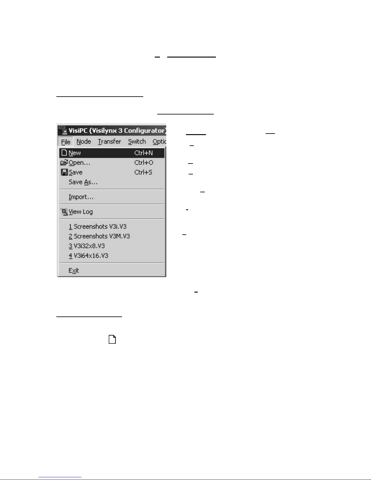
3.1 File Menu Commands
Figure 4 File Menu
Click
To
New
Create a new ‘default’ configuration
set-up.
Open
Open an existing configuration set-up
Save
Save an open configuration set-up
using the same file name
Save As
Save an open configuration set-up to
a specified filename
Import
Allows you to import an existing
configuration file and merge it with
the open configuration
View Log
Select ‘View Log’ to see the error log
for the selected configuration.
Note: if no errors exist, the log will
not be available.
File
History
This is the recent files list. The four
most recently accessed files are
shown here, for selection.
Exit
Allows you to exit the entire VisiPC
program.
3.1.1 New Command
Shortcut keys:
Ctrl-N, Alt-FN
Toolbar:
Use this command to create a new default Visilynx 3 configuration set-up. Prior to sending
the command, a warning is given to remind the user that the Visilynx 3 factory default
configuration will be restored.
VisiPC Software Manual Part 1 – Visilynx 3 Configurator
INS00231 Issue 4 Page 10 of 88
Figure 5 Visilynx Defaults Warning
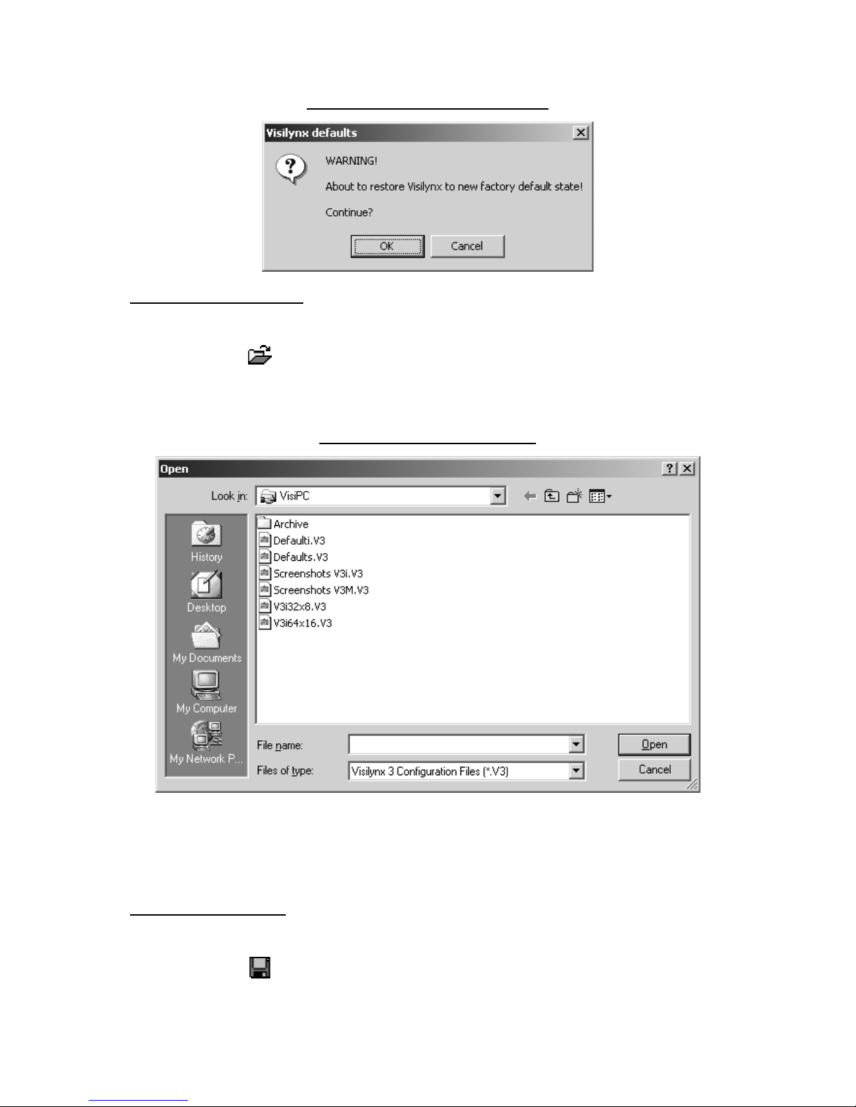
3.1.2 Open… Command
Shortcut keys:
Ctrl-O, Alt-FO
Toolbar:
Use this command to open an existing configuration set-up. This will overwrite your currently
open configuration set-up.
Figure 6 'File Open' Dialog Box
The dialog box allows you to select a previously saved configuration file for use (in this case
from a choice of just three). Selection is made by either double-clicking the chosen file, or by
highlighting the chosen file and clicking
Open,
or by typing the name, e.g. Control Centre.V3,
into the file name box and then clicking
Open
.
3.1.3 Save Command
Shortcut keys:
Ctrl-S, Alt-FS
Toolbar:
VisiPC Software Manual Part 1 – Visilynx 3 Configurator
INS00231 Issue 4 Page 11 of 88
Use this command to save the current configuration to its current name and directory. When
you save a document for the first time, Visilynx 3 configuration displays the ‘Save As…’
Dialog Box so you can name your document. If you want to change the name and directory
of an existing document before you save it, choose the ‘Save As…’ command.1
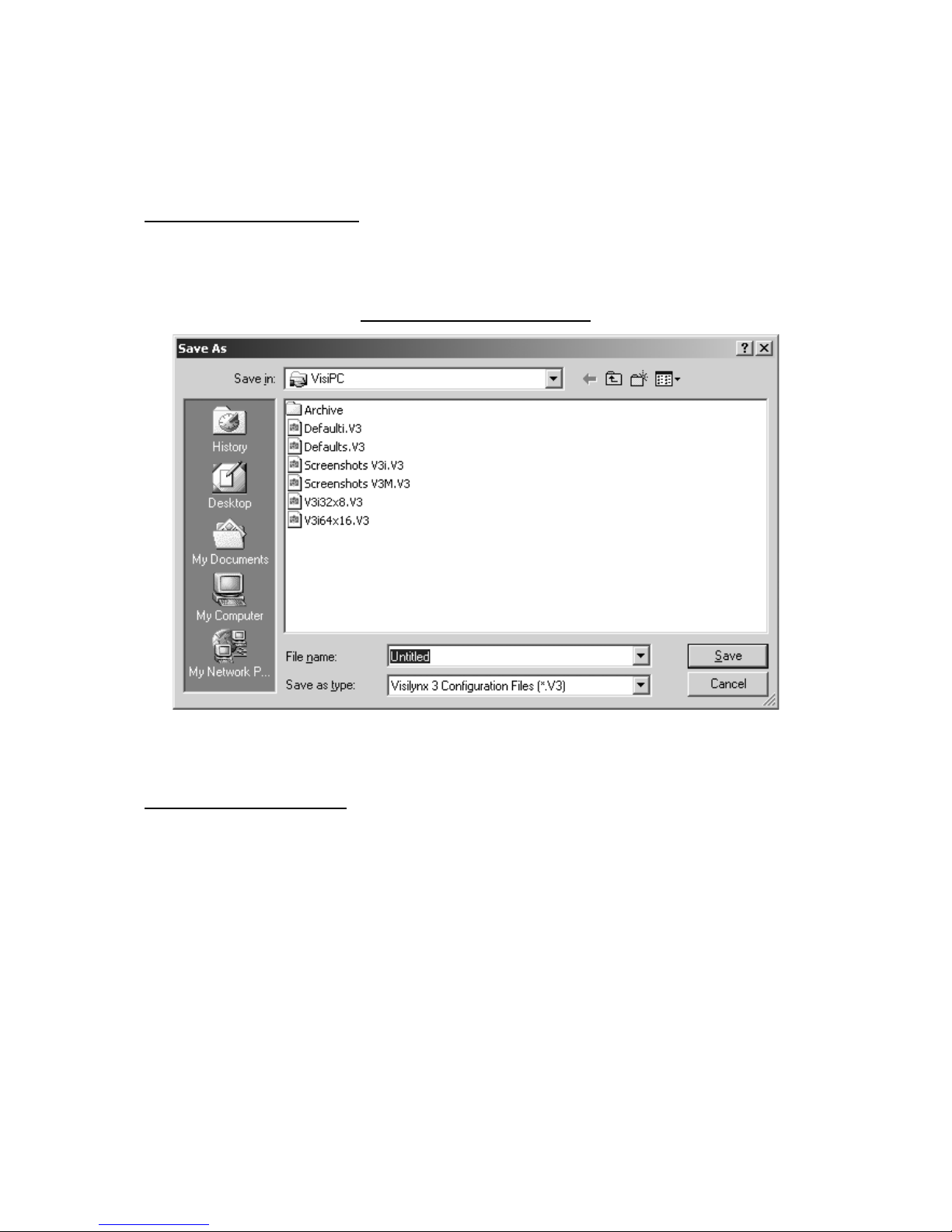
3.1.4 Save As… Command
Shortcut keys:
Alt-FA
This command allows you to specify the name and location of the file you are about to save.
Figure 7 'Save As' Dialog Box
Type in the desired new file name in place of the highlighted file name, and then click on
Save
. This will save the file to the selected folder.
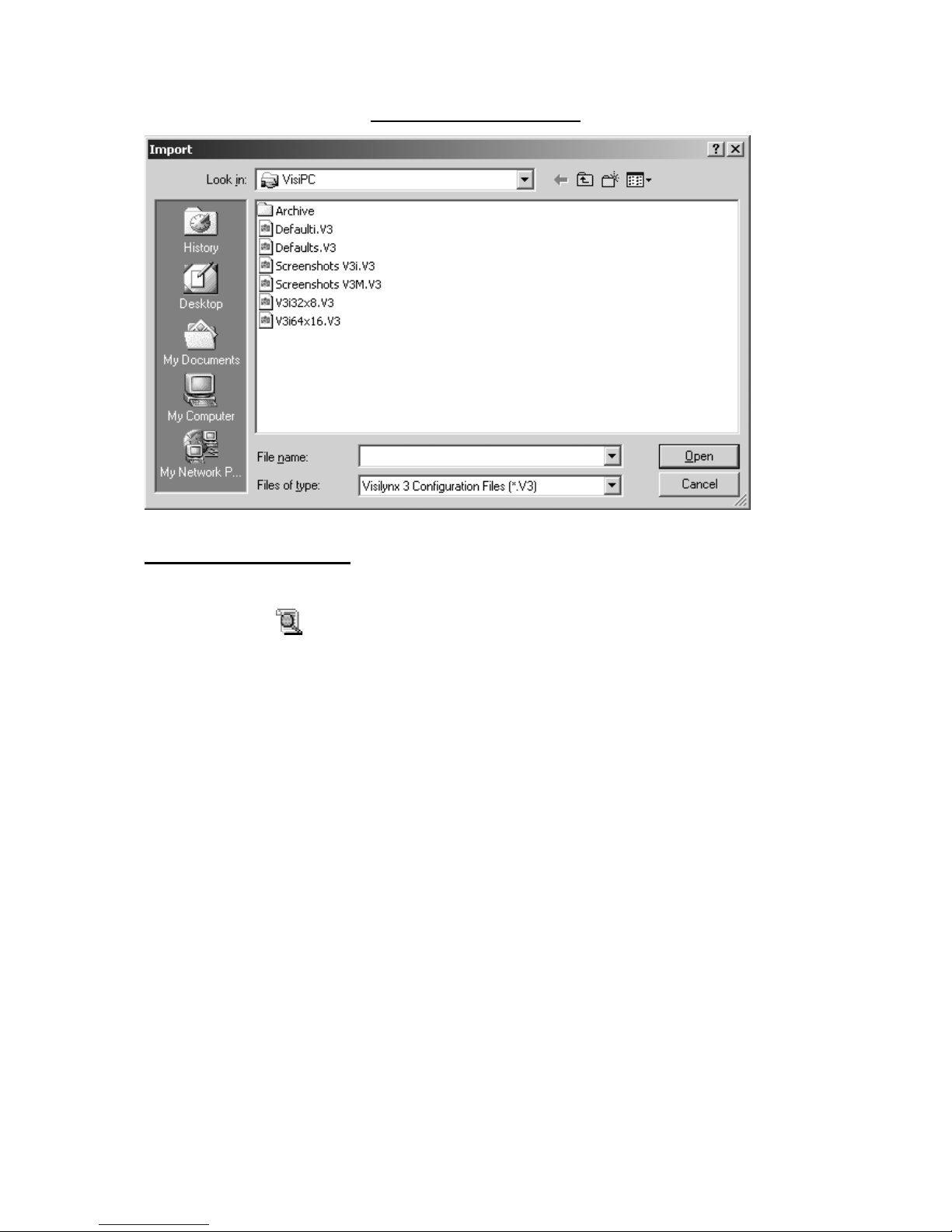
3.1.5 Import… Command
Shortcut keys:
Alt-FI
This command allows the user to import configuration files into the configuration being
edited. This is useful for merging part of another configuration file (extracted into a new file
using a text editor) into one or more other configuration files. Note that only files saved in the
VisiPC format may be imported.
VisiPC Software Manual Part 1 – Visilynx 3 Configurator
INS00231 Issue 4 Page 12 of 88
Figure 8 Import Dialog Box
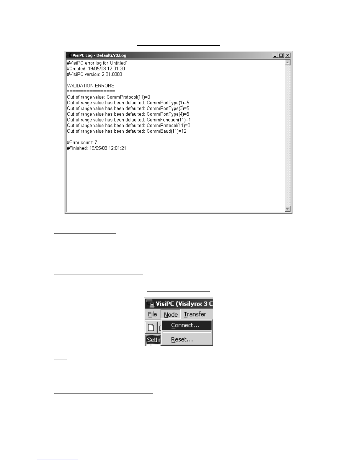
3.1.6 View Log Command
Shortcut keys:
Alt-FV
Toolbar:
The log records all of the errors found during loading or validating a particular configuration
and lists them for reference, as shown above. The system will log all errors made as they
happen. The log shows errors detected by VisiPC’s extensive crosschecks, and indicates
whether they have been corrected (by assigning a default value) or need to be manually
corrected. Even those that have been defaulted may not be appropriate and should
therefore be checked for suitability.
VisiPC Software Manual Part 1 – Visilynx 3 Configurator
INS00231 Issue 4 Page 13 of 88
Figure 9 VisiPC Log Window
3.1.7 Exit Command
Shortcut keys:
Alt-F4
Use this command to close VisiPC.
3.2 Node Menu Commands
Figure 10 Node Menu
Note: Node menu commands are not currently implemented by Visilynx 3 software. A
warning is provided.
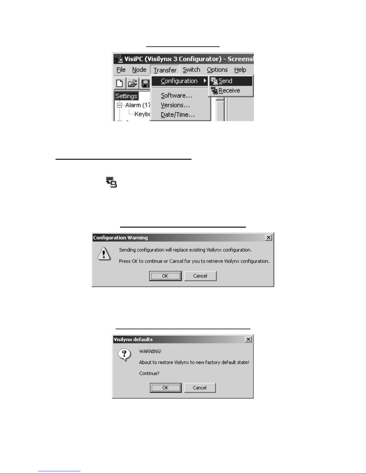
3.3 Transfer Menu Commands
These commands are used to transfer data to and from the Visilynx 3 system.
VisiPC Software Manual Part 1 – Visilynx 3 Configurator
INS00231 Issue 4 Page 14 of 88
Figure 11 Transfer Menu
Use the ‘Configuration’ ‘Send’ and ‘Receive’ commands to send or receive a file to or from
the system.
3.3.1 Transfer Configuration Send Command
Shortcut keys:
Alt-TCS
Toolbar:
‘Send’ is used to transfer the content of a configuration file to the Visilynx 3 system. Prior to
sending, a warning is given to remind the user that the existing configuration in the Visilynx 3
system will be overwritten.
Figure 12 Configuration Warning Message
If File New has been done and no changes have been made to the configuration, the status
bar will show ‘Defaults’. Sending this configuration will replace the factory default data in the
Visilynx 3 system. An additional warning message is given before this process starts.
Figure 13 Visilynx Defaults Warning Message
After the above warning(s) the communication process is performed.
VisiPC Software Manual Part 1 – Visilynx 3 Configurator
INS00231 Issue 4 Page 15 of 88
3.3.2 Transfer Configuration Receive Command
Shortcut keys:
Alt-TCR
Toolbar:
‘Receive’ is used to collect a configuration from the Visilynx 3 system, for backup purposes.
It is highly recommended that the received configuration should be saved to disk before
making any changes.
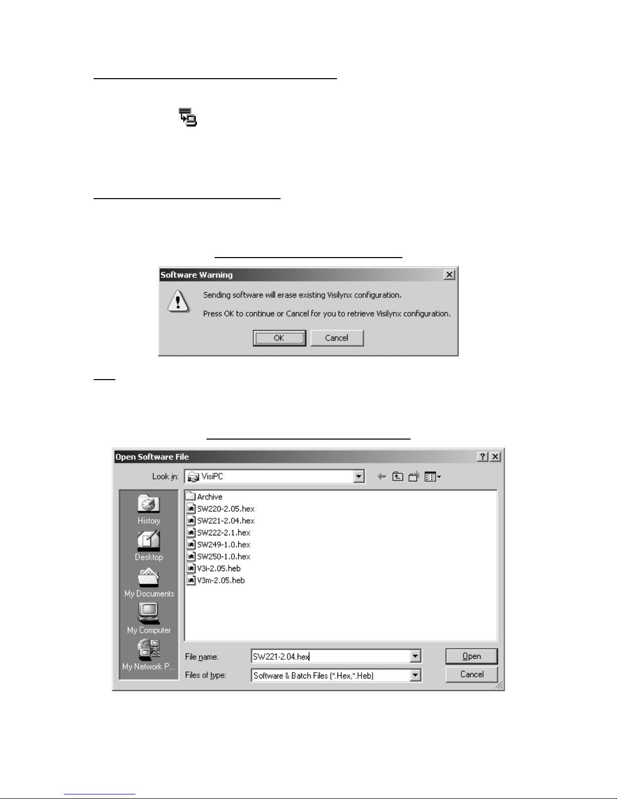
3.3.3 Transfer Software… Command
A warning is given to remind you that any configuration in the system will be erased during
software transfer.
Figure 14 Software Warning Message
Note: If you do not have a copy of the last configuration transferred to the Visilynx 3 system,
or if it has been changed by keyboard users since being transferred (sequences, views or
zones may have been changed), then you should first transfer the configuration from Visilynx
3. You can then transfer it back again after the new software is loaded.
Figure 15 Open Software File Dialog Box

VisiPC Software Manual Part 1 – Visilynx 3 Configurator
INS00231 Issue 4 Page 16 of 88
The ‘Open Software File’ option is used to select the software to be transferred to the FLASH
memory in the Visilynx 3 CPU. Once the file has been selected, click the
Open
button and
the transfer process will begin
V3i software is distributed in these files; where V.vv is the software version:
SW220-V.vv.hex Main Controller software.
SW221-V.vv.hex Flash Boot Loader software.
SW249-V.vv.hex V3i FPGA firmware.
SW250-V.vv.hex V3i European display font data.
SW251-V.vv.hex V3i European and Asian display font data
V3M software is distributed in these files; where V.vv is the software version:
SW220–V.vv.hex Main Controller Software.
SW221–V.vv.hex FLASH Boot Loader software.
SW222–V.vv.hex CPU FPGA firmware.
A batch transfer mode is also available, which sends a set of software files in one request. A
batch transfer file list is stored in a text file with a “.heb” extension. Filenames may include a
full path. Comments are preceeded by #. For example:
# V3i-2.05.heb
# VisiPC batch file for loading all software components into V3i
# V3i FPGA firmware
SW249-1.0.hex
# V3i European font data
SW250-1.0.hex
# V3i/V3m Flash Boot Loader software
SW221-2.04.hex
# V3i/V3m main controller software
SW220-2.05.hex
3.3.4 Transfer Versions… Command
Shortcut keys:
Alt-TV
Selecting the Transfer/Versions… menu brings up the ‘Software Version’ dialog.
Figure 16 Software Version Dialog Box
The ‘Software Version’ command is used to query the local Visilynx 3 node software
versions. (Note: only the local node (L), can currently be queried). Choose from the ‘Version
Type’ selector options available (Visilynx FPGA firmware, Visilynx main software, Visilynx
flash boot loader, Visilynx configuration and Visilynx font). Now click the
Send
button. The
software version is then displayed in the ‘Version’ field.
VisiPC Software Manual Part 1 – Visilynx 3 Configurator
INS00231 Issue 4 Page 17 of 88
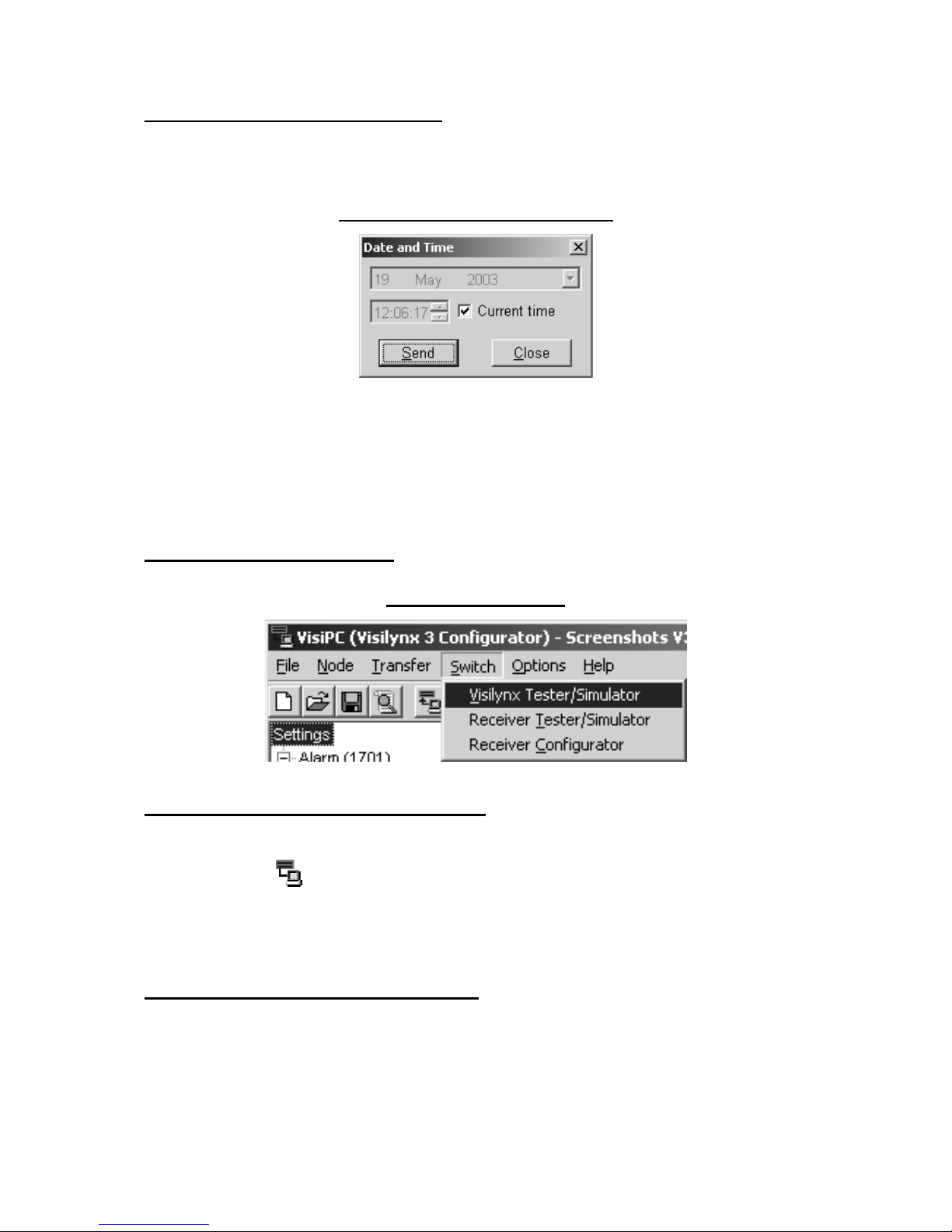
3.3.5 Transfer Date/Time… Command
Shortcut keys:
Alt-TD
Selecting the Transfer/Date/Time… menu brings up the ‘Date and Time’ dialog.
Figure 17 Date and Time Dialog Box
The ‘Date and Time’ option allows you to set the date and time for the Visilynx 3 system as a
whole. You can either use the computer’s internal clock settings by ticking the ‘Current time’
box or untick the box and specify your own time settings. Click on the
Send
button to
transfer these settings to the entire system, including all video displays and keyboard LCD
panels.
3.4 Switch Menu Commands
Figure 18 Switch Menu
3.4.1 Visilynx 3 Tester/Simulator Command
Shortcut keys:
Alt-SV
Toolbar:
Select this option to switch to the Visilynx 3 Tester & Simulator sub-program. VisiPC will
disappear for a few seconds while the Visilynx 3 Tester & Simulator Main tab loads (see
page 85).
3.4.2 Receiver Tester/Simulator Command
Shortcut keys:
Alt-ST
Select this option to switch to the RX3 Receiver Tester & Simulator sub-program. VisiPC will
disappear for a few seconds while the RX3 Receiver Tester & Simulator ‘Status Log’ tab
loads.
VisiPC Software Manual Part 1 – Visilynx 3 Configurator
INS00231 Issue 4 Page 18 of 88
3.4.3 Receiver Configurator Command
Shortcut keys:
Alt-SC
Select this option to switch to the RX3 Receiver Configurator sub-program. VisiPC will
disappear for a few seconds while the RX3 Receiver Configurator screen loads (see page
86). Note: This software currently has restricted functionality.
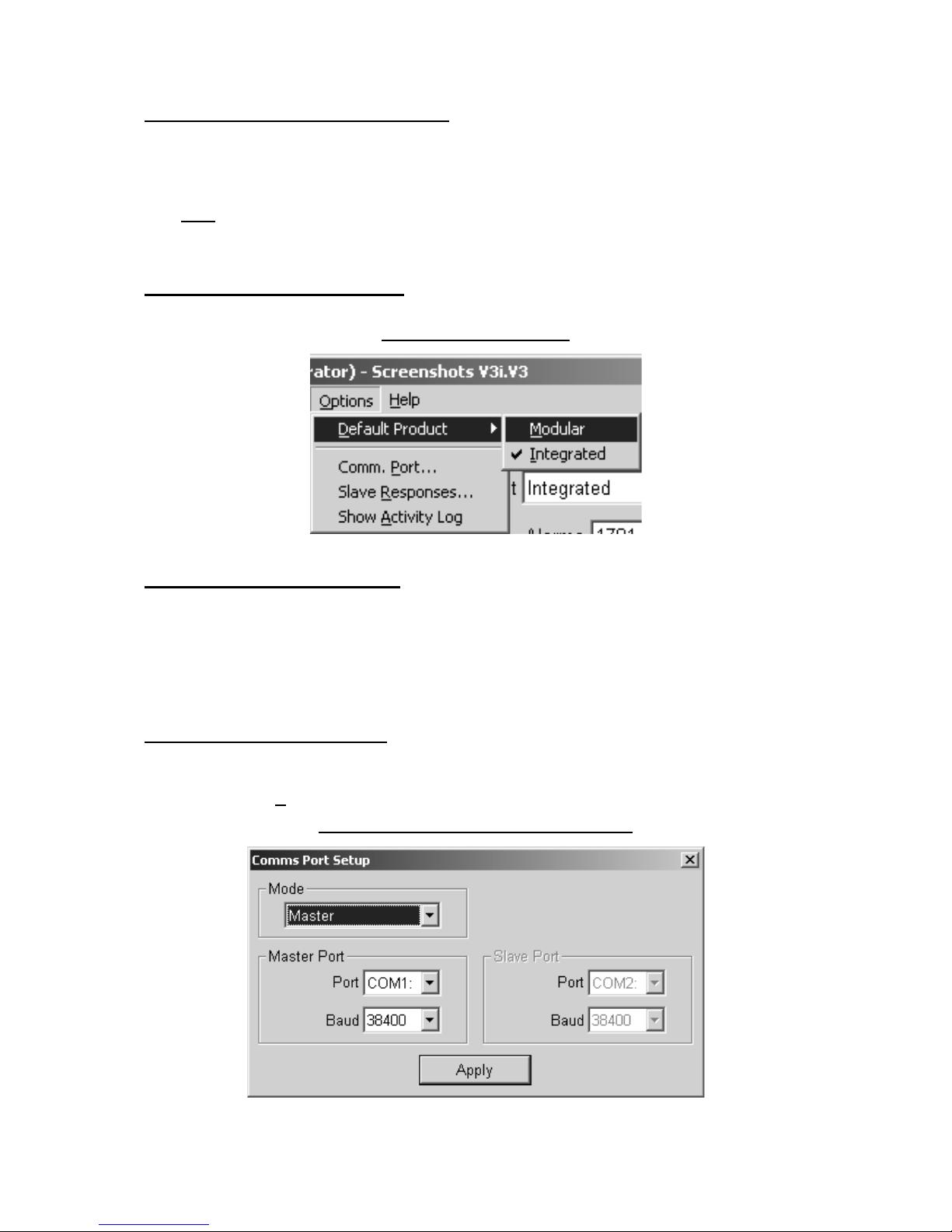
3.5 Options Menu Commands
Figure 19 Options Menu
3.5.1 Default Product Command
Shortcut keys:
Alt-ODM, Alt-ODI
Select either ‘Modular’ or ‘Integrated’ from the ‘Default Product’ submenu. This selects an
internal set of default values and range limits for the selected product and selects one of two
factory default files that will be loaded by File/New. These two default files have reserved
filenames to ensure they cannot be altered by the user.
3.5.2 Comm. Port… Command
Shortcut keys:
Alt-OP
Selecting ‘Comm. Port...’ brings up the Comms Port Setup dialog box.
Figure 20 Comms Port Setup Dialog Box

VisiPC Software Manual Part 1 – Visilynx 3 Configurator
INS00231 Issue 4 Page 19 of 88
The ‘Mode’ selector selects whether the VisiPC program is acting as a Master, Slave or both.
For most purposes, ‘Master’ Mode should be selected. The ‘Port’ and the ‘Baud’ rate are
selected independently for both the Master and the Slave ports, as required. The ‘Master
Port’ or the ‘Slave Port’ selection box is greyed out if the selected mode does not use it.
There are up to 4 serial communication ports (COM1 to COM4) available on most PCs. All
four ports are listed, whether or not they are fitted. Baud is the rate of data transfer between
the PC and Visilynx 3, sometimes known as the port speed. Both the Master and Slave Port
Baud rates are set to 38400 baud on the first start-up of the program after installation. Other
port parameters are fixed (8 data bits, 1 stop bit, no parity).
Pressing the
Apply
button applies the selected values to the ports.
The Comm Port Setup dialog box won't close when the
Apply
button is pressed if the port
configuration is invalid; i.e. one or both ports cannot be initialised. If only one port is
available, select a mode that uses only one port and select the unused port. If no ports are
available, the dialog box can still be closed by clicking the cross in the top right corner of the
dialog box. This will close the dialog box although the settings are invalid. All
communication functionality will be disabled.
3.5.3 Slave Responses… Command
Shortcut keys:
Alt-OR
The ‘Slave Responses’ option is only available if either ‘Slave’ or ‘Master & Slave’ Mode field
has been selected in Comms Port Setup (see above).
Selecting
Slave Responses…
brings up the ‘Set Slave Responses’ dialog.
Figure 21 Set Slave Responses Dialog Box
The values entered are used in the replies from the Slave mode, when the Master asks for
information.
Note: This mode is not normally used, and can be ignored. More details for use can be
found in the manual for VisiPC Visilynx 3 Tester & Simulator (INS00237).
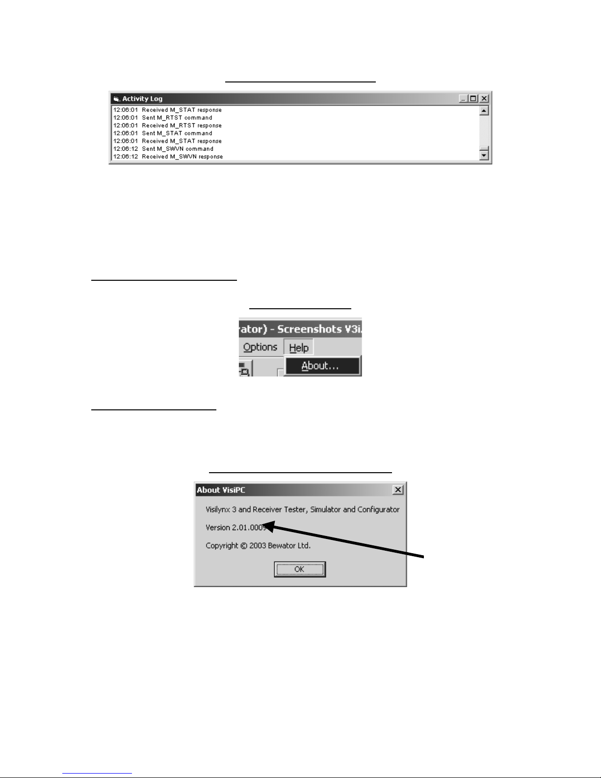
3.5.4 Show Activity Log Command
Shortcut keys:
Alt-OA
Selecting ‘Show Activity Log’ shows a separate window in which a summary of the Master
messages sent and received is recorded.
VisiPC Software Manual Part 1 – Visilynx 3 Configurator
INS00231 Issue 4 Page 20 of 88
Figure 22 Activity Log Window
The window opens immediately below the main VisiPC Window. The size and position of the
window can be changed by the user.
The ‘Activity log’ can be copied by clicking on the Activity Log window and then pressing
Ctrl-C. This copies the contents to the clipboard from where they can be pasted into any text
editor or word processor.
3.6 Help Menu Commands
Figure 23 Help Menu
3.6.1 About… Command
Shortcut keys:
Alt-HA
Selecting ‘About…’ brings up the About VisiPC message box.
Figure 24 About VisiPC Message Box
‘About VisiPC’ offers the following information, for reference:
•
Software name.
•
Software version number.
•
Copyright information.
Selecting OK closes the window.
Example of
software version
number

VisiPC Software Manual Part 1 – Visilynx 3 Configurator
INS00231 Issue 4 Page 21 of 88
4 SYSTEM SETTINGS
4.1 Introduction
The system settings are the building blocks for each configuration. ‘Global System Settings’
are adjusted to accurately reflect the installed equipment. Once configured and accepted,
the individual system parts will appear in the ‘Settings’ tree menu on the left-hand side of the
screen, with the total number of each installed component appearing in brackets.
All adjustments are made in the window on the right.
4.2 Shortcut Keys
The numeric fields on this and other screens may be altered in the following ways:
•
Use the mouse to click on the arrows next to each field to increase or decrease the
number.
•
Highlight the field by clicking on it and then type the adjusted figure.
•
Highlight the field by clicking on it and then adjust the figure using the keys:
‘Up arrow’ to increase by 1
‘Down arrow’ to decrease by 1
‘Page Up’ to increase by 10
‘Page Down’ to decrease by 10
‘Home’ to select the lowest value
‘End’ to select the highest value.
All screen selection mouse buttons have computer keyboard shortcuts, activated by pressing
the
Alt
key at the same time as a letter key denoted by an underlined character. These
shortcuts work on most screens:
Accept Alt-A, Enter
or
Shift-Enter
(see below)
Restore Alt-R
Default Alt-D
Select None Alt-N
Select All Alt-L
Copy Previous Alt-C
The
Accept
button is the default button on each page when any field has been changed.
This means that pressing
Enter
has the same effect as clicking on the button or pressing
Alt-
A
. A further time-saver is to use
Shift-Enter
, which, on screens with multiple pages to
configure, will first accept the changes on the current page and then select the next page.
Note: The example screenshots appearing in this chapter are for a V3i system with as many
options shown as possible, i.e. ‘Integrated’ was selected as the ‘Default Product’ at the
‘Options’ Menu (see page 18). Any changes required for operations with a V3M system are
identified within the text.
There follows a description of each available page of settings.
VisiPC Software Manual Part 1 – Visilynx 3 Configurator
INS00231 Issue 4 Page 22 of 88
4.3 Global System Settings
When the VisiPC software is first installed, or when a new configuration is created using
‘File/New’, factory default values will appear for all of the ‘Global System Settings’, as shown
below.
Figure 25 Global System Settings - V3i Default Screenshot
On first selection the ‘Configurator’ sub-program always starts with the ‘Integrated’ Product
selected. On subsequent selections the ‘Configurator’ sub-program starts up by loading the
last configuration file used, including the selected product.
If a ‘Modular’ configuration file is loaded and then the Product selector is changed to
‘Integrated’, a warning is given that the screen values will change, if required, to fit the new
system limits.
Figure 26 Product Selector – Integrated
You may now adjust the default or loaded ‘Global System Settings’ to reflect the actual
system parameters for either the V3i or the V3M system installation. When you are happy
with the ‘system’ values, you can save the set-up using the ‘Save configuration file to disk’
icon or the ‘Save’ command in the ‘File’ menu.

VisiPC Software Manual Part 1 – Visilynx 3 Configurator
INS00231 Issue 4 Page 23 of 88
The Product selector is provided to select ‘Modular’ or ‘Integrated’, which affects various
maximum values and some defaults throughout the configuration screens (see Table 3).
If a value is reduced to zero, the feature is assumed not to be installed, and will not be
displayed in the settings menu on the left-hand side. A minimum value is applies to the
following items:
•
Cameras = 1
•
Comms Channels = 11
•
Monitors = 1
•
Nodes = 1
•
Users = 1
•
Zone size = 1
A minimum value has been assigned to these items to ensure that the system is still
functional even in its most basic form. All of the remaining values can be reduced to zero, if
required.
In addition to minimum values, maximum values apply to each feature. You will find that you
are unable to increase the values of each feature beyond this point. The maximum value
assigned to each system feature is different for V3i and V3M systems, as shown below.
Table 3 Maximum Quantities
Maximum Quantities
Feature
V3i V3M
Alarms 1701 1701
Cameras 64 511
Camera Maps 1 2
Comms. Channels 21 43
Internal Quads 4* 32
Keyboards 32 32
Monitors 16 128
Multiplexers 32 32
Nodes 127 127
Node Trunks 64 64
Relays 8 255
Sequences 64 64
Telemetry Cards 4 32
Timed Events 128 128
Users 64 64
VCR/DVRs 32 32
Views 255 255
Zones 255 255
Zone Size 8 8
Key: * Optional expansion cards fitted.
•
Accept
: will save the settings for the current page.
•
Restore
: will return all of the settings for the current page to the point when the
configuration was last saved using
Accept
.
•
Default
: will restore the settings to valid default values for the current page.
When Accept is clicked, the program will perform a validation procedure to detect errors or
imbalances with regard to system settings and report these in the system log. The system
log is accessible via the ‘view log’ facility within the File menu or from the toolbar. If an error
VisiPC Software Manual Part 1 – Visilynx 3 Configurator
INS00231 Issue 4 Page 24 of 88
is detected, the system will show you an error message saying, for example, ‘Configuration
verification found 6 error(s)! See log file’. The error log is updated each time an error occurs.
Now proceed to the individual component parts of the configuration, starting with the Alarm
Settings menu detailed below.
4.4 Alarm Settings
‘Alarm Settings’ allows you to set up each alarm on the system. The tree on the left
highlights ‘Alarm’ and shows the total number of alarms configured for the system in brackets
(in this case 1701).
Notes:
For a V3i single unit (with 32 camera inputs), ‘Alarm’ numbers 1 to 32 are always allocated to
video loss alarms. Therefore the 128 possible Alarm Inputs MUST be allocated to ‘Alarm’
number 33 onwards.
For a V3i expanded unit pair (with 64 camera inputs and 256 alarm inputs), the video loss
alarms occupy the range 1 to 64. Therefore the 256 alarm inputs MUST be allocated to
‘Alarm’ number 65 onwards.
For V3M, the first ‘n’ alarms are video loss alarms, where ‘n’ is the number of camera inputs
on the system (16 per camera input card).
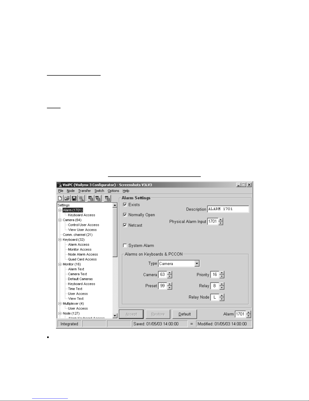
Figure 27 Alarm Settings Screenshot
Use the
Alarm
selector (bottom right) to select the one to configure.
•
Exists
: You must first tell the system whether an alarm is in use or not. This is done by
putting a tick in the ‘Exists’ box.
When the ‘Exists’ box is ticked, further information will be displayed.

VisiPC Software Manual Part 1 – Visilynx 3 Configurator
INS00231 Issue 4 Page 25 of 88
•
Description
: Each alarm can be given a name, up to 16 characters long, e.g. ‘Front
Entrance’. It can be labelled as anything you want, but should reflect the alarm position
or type in some way. During an alarm scenario, this text will be displayed on the alarm
monitor(s).
•
Normally Open
: Tick this if it is known that the alarm input is normally open-circuit, but
becomes closed-circuit when it becomes active under alarm conditions. In the case of
video loss alarm inputs, this box should be ticked.
•
Physical Alarm Input
: Select the number of the physical input connector on the
hardware that you wish assign to the current ‘logical’ alarm number (bottom right).
•
Netcast
: is short for 'Network Broadcast'. If ticked, triggering the alarm will cause all
other nodes on the network to be informed. Then, those keyboards on other nodes that
have Node Alarm Access ticked for this node will also be able to handle the alarm.
•
Cascade
: When available and this box is ticked, the Visilynx 3 system will activate both
the selected alarm and the alarm after it. For example if alarm 5 is activated and it had
the cascade box ticked, both alarm 5 and alarm 6 will be activated. If alarms 5 and 6
have cascade ticked, 5, 6 and 7 will be activated. This means that in the event of an
alarm, the system can be configured to respond with a cascade of alarms instead of just
one, offering a flexible combination of actions to be triggered. This feature is not present
for the last alarm (as shown in the screenshot above).
•
System Alarm
: Tick this to have the alarm handled as a system alarm. This tick box is
the same configuration item as is configured by the ‘System Alarm Access Settings’
screen (see page 64), but acts only on the selected alarm.
If ‘System Alarm’ is unticked, various options are available in the ‘Alarms on Keyboards &
PCCON’ frame.
Three selections (Priority, Relay and Relay Node) are available for all ‘Type’ selections. The
other options available vary according to the ‘Type’ selection.
•
Type
: First choose one of the following options in the ‘Type’ selector.
•
None
: The alarm does not display text on keyboards or on their alarm monitors.
•
Camera
: (as shown above) First select the camera number, or none. If there is a
camera number, then a preset number may also be selected.
•
View
: Select a view number.
•
Trunk
: No extra options are available.
•
Relay only
: No extra options are available.
Now set up any additional parameters for the selected option:
•
Priority
: All alarms regardless of type have an associated priority, which is used
when two or more active alarms are attempting to control the same camera. Priority
1 is the highest priority, 16 the lowest, and 0 disables priority checking.
•
Relay
: All alarms regardless of type can activate a relay, in addition to the type
action. If set to ‘---‘, no relay is switched. This is useful if the alarm is not required to
take any action, but is just to be displayed on monitors and keyboards. In this case
‘Alarm Type’ should be set to ‘Relay Only’ and ‘Relay’ set to ‘---‘.
•
Relay Node
: Only relays on the local node can be controlled by the current Visilynx
software.
•
Accept
: will save the settings for the current page.
VisiPC Software Manual Part 1 – Visilynx 3 Configurator
INS00231 Issue 4 Page 26 of 88
•
Restore
: will return all of the settings for the current page to the point when the
configuration was last saved using
Accept
.
•
Default
: will restore the settings to valid default values for the current page.
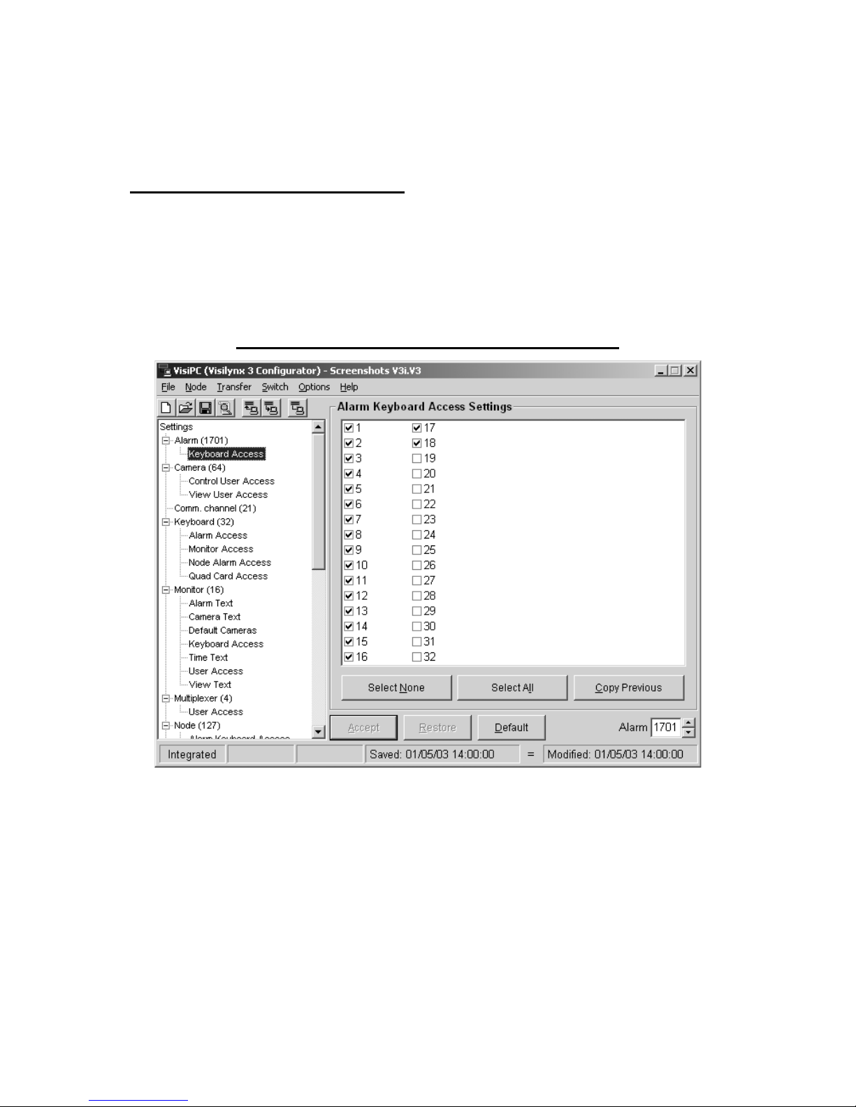
4.4.1 Alarm Keyboard Access Settings
‘Alarm Keyboard Access Settings’ assigns permission to each keyboard that is allowed to
manage and view the selected alarm. The alarm images are viewed on the keyboard alarm
monitors. If the same alarm is configured as both a Keyboard Alarm and a System Alarm
(see page 63), only the System Alarm Setting will be used by the Visilynx 3 system.
This is the same list as is configured by the ‘Keyboard Alarm Access Settings’ screen (see
page 35), but arranged by alarm number rather than keyboard number.
Figure 28 Alarm Keyboard Access Settings Screenshot
•
Use the
Alarm
selector (bottom right) to select the one to configure.
•
Tick the box adjacent to each keyboard on the system that will be allowed to handle the
alarm.
•
Select None
: will untick all of the boxes simultaneously.
•
Select All
: will tick all of the boxes simultaneously.
•
Copy Previous
: will duplicate the list from the previous alarm number into this list, if the
list needs to be the same.
•
Accept
: will save the settings for the current page.
•
Restore
: will return all of the settings for the current page to the point when the
configuration was last saved using
Accept
.

VisiPC Software Manual Part 1 – Visilynx 3 Configurator
INS00231 Issue 4 Page 27 of 88
•
Default
: will restore the settings to valid default values for the current page.
4.5 Camera Settings
‘Camera Settings’ allows you to set up each camera on the system. The tree on the left
highlights ‘Camera’ and shows the total number of cameras configured for the system in
brackets.
Figure 29 Camera Settings Screenshot
•
Use the
Camera
selector (bottom right) to select the one to configure.
•
Description
: Each camera can be given a name, up to 16 characters long. This text will
appear on a monitor screen when this camera is selected, and on keyboard camera
menus.
•
Physical Camera Input
: This will only appear if you have defined one or more camera
maps in the ‘Global System Settings’ screen (see page 21). Each camera will have a
physical address defined by its physical connector position at the rear of the matrix, e.g.
camera 3 is connected to input 3 at the matrix. When a camera map has been set up,
the cameras within the map can be accessed using alternative addresses, e.g. camera 3
can be accessed as camera 21 or some other number.
This is particularly useful when adding cameras to the system at a later date. You can
now allocate logical, sequential numbers to a group of cameras in the same location,
even if several of these are new additions to the installation. In the past, these cameras
would have to be allocated the same number as their ‘physical’ position at the matrix,
which would mean that, for example, cameras 6, 7, 8 and 9 would be grouped with
 Loading...