

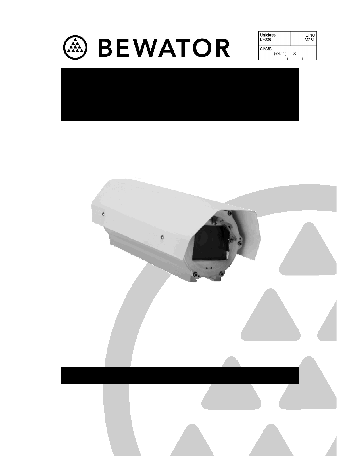
FH07B Series
Phoenix™ 7” Flameproof
Camera Housing
INS00306 Page 1 of 24
Installation Instructions
Manual: INS00306 Issue: 3.0

FH07B Series Installation Instructions Issue 3.0
INS00306 Page 2 of 24
IMPORTANT NOTE
Please thoroughly read these Instructions before installing the
FH07B Series Phoenix™ 7” Flameproof Camera Housing.
Table of Contents
About This Manual...................................................................................................................................3
Health & Safety Notice.............................................................................................................................3
INTRODUCTION......................................................................................................................................5
General Description .................................................................................................................................5
Contents of Package................................................................................................................................9
Before Starting Installation.......................................................................................................................9
After Installation .......................................................................................................................................9
Suggested Tools....................................................................................................................................10
ORDERING THE FH07B SERIES UNIT ...............................................................................................11
Certification Requirements For The Camera/Lens ................................................................................11
INSTALLING THE FH07B SERIES UNIT.............................................................................................12
Removing The Rear Cap Assembly.......................................................................................................12
Pre-installation Wiring............................................................................................................................13
Refitting The Rear Cap Assembly And Fitting The Sunshield...............................................................18
Locating The Unit...................................................................................................................................19
Mounting The Unit..................................................................................................................................19
MAINTENANCE.....................................................................................................................................20
1 Month After Installation .......................................................................................................................20
6 Monthly Checks...................................................................................................................................20
2 Yearly Checks.....................................................................................................................................20
5 Yearly Checks.....................................................................................................................................20
SPECIFICATIONS.................................................................................................................................21
Mechanical.............................................................................................................................................21
Electrical.................................................................................................................................................21
Mechanical Dimensions.........................................................................................................................22
Wiring Diagram ......................................................................................................................................23
NOTES...................................................................................................................................................24

FH07B Series Installation Instructions Issue 3.0
INS00306 Page 3 of 24
About This Manual
This manual describes the following equipment, certified to the EC (ATEX) Directive
94/9/EC as
II 2 GD (EEx d IIB T85°C):
FH07B-40 Phoenix™ 7” diameter, IP67, Camera Housing (420 x114 x 93mm
internal) c/w sunshield, demister ~ 230Vac.
FH07B-40/L Phoenix™ 7” diameter, IP67, Camera Housing (420 x 114 x 93mm
internal) c/w sunshield, demister ~ 24Vac.
FH07B-40/U Phoenix™ 7” diameter, IP67, Camera Housing (420 x 114 x 93mm
internal) c/w sunshield, demister ~ 110Vac.
FH07B-30 Phoenix™ 7” diameter, IP67, Camera Housing (290 x 114 x 93mm
internal) c/w sunshield, demister ~ 230Vac.
FH07B-30/L Phoenix™ 7” diameter, IP67, Camera Housing (290 x 114 x 93mm
internal) c/w sunshield, demister ~ 24Vac.
FH07B-30/U Phoenix™ 7” diameter, IP67, Camera Housing (290 x 114 x 93mm
internal) c/w sunshield, demister ~ 110Vac.
Health & Safety Notice
SELECT SUITABLE EQUIPMENT
• Please ensure that all equipment is suitable for the application and the environment for
which it is intended.
• Check operating temperatures and where applicable “protection against water ingress”
specifications.
• Please take particular care that the inter-connected equipment is fully compatible with
each other and suitable for such use.
• Check load ratings and dimensions.
SECURELY MOUNT THE ASSEMBLY
• This equipment may be subject to remote control and may move at any time . It should be
installed such that moving parts cannot be exposed to anyone. Pers ons working on the
equipment should take appropriate precautions to ensure that unexpected movement does
not occur as this could lead to injury.
• This unit must be mounted properly and securely.
• In situations where there could be a risk of injury, should any part of the assembly beco me
detached for any reason and fall, normal safety precautions should be employed.
• Care should be exercised to select suitable hardware to install the unit, taking into
account both the compositions of the mounting surface and the total weight of the
hardware.
• It is important that only the recommended or supplied fixings are used. In some cases
the fixings material and other details are critical.
• Ensure that each part of the assembly is attached securely.

FH07B Series Installation Instructions Issue 3.0
INS00306 Page 4 of 24
• The mounting surface must be sufficiently solid and strong to take the complete weight of
the assembly and take into account environmental aspects such as exposure to strong
wind.
• It is recommended that the bracket and column spacers detailed on Page 21 should be
used, where appropriate.
• As the mounting surface to which this housing could be attached is site dependent,
Bewator Ltd. does not supply fixings for securing the base of the unit to its mounting
surface. It is the responsibility of installers to ensure that fixings are selected that are fit for
the specific purpose required.
INSTALL OUT OF REACH
• This equipment is to be installed out of reach of the user, or anyone who will come into
casual contact with the installation.
• It is recommended that a prominent warning notice be affixed near to all moveable
Camera Housing assemblies indicating that sudden movement of the equipment may
occur.
• Be sure to provide suitable access equipment to ensure the safety of installation or
service personnel working on the equipment.
INSTALL CORRECTLY
• All persons installing and maintaining this equipment should be suitabl y qualified and work
to national and local standards and codes of practice.
• Use the appropriate tools. Specific tools may be required for installation purposes
dependant upon the site in which the assembly is to be installed.
• The installation should comply with local codes and standards e.g. EN 60079–14:1997
and its guide PD 60079-14:2000.
• Check that correct cable types and input cable glands are used - Refer to local and
national standards for wiring and follow recommendations.
• Always use the recommended or supplied screws. Failure to do so will invalidate the
certification to EC (ATEX) Directive 94/9/EC.
• Ensure that power is removed from the assembly before attempting installation.
• Ensure the power CANNOT be re-connected by external sources while the unit is being
worked upon.
• Installation must comply with data protection and privacy codes of practice.
WARNINGS
The unit must be connected to Earth.
Do not open the unit when an explosive atmosphere is present.

FH07B Series Installation Instructions Issue 3.0
INS00306 Page 5 of 24
Introduction
General Description
Hazardous Areas
The Phoenix™ 7” FH07B Series Flameproof Camera Housing is certified to the EC (ATEX)
Directive 94/9/EC for use in hazardous areas.
A hazardous area is defined as an area in which explosive atmospheres are, or may be
expected to be, present in quantities such as to require special precautions for the
construction and use of electrical equipment. An explosive atmosphere consists of a mixture
of flammable substances with air in the form of gas, vapour, mist or dust in such proportions
that it can be exploded by excessive temperatures, arcs, sparks or flames.
Equipment is housed in an enclosure into which gas may gain access. Should this gas be
ignited within the enclosure, the resulting explosion will not reduce the pressure integrity of
the enclosure or will not be transmitted to any flammable atmosphere external to the
enclosure.
Note: This equipment may contain an ignition source even after disconnection.
Customer Orders
The FH07B Series of Flameproof Camera Housings are fitted with a customer (free issue)
supplied Camera and Lens and supplied with ATEX Equipment Certification by Bewator Ltd.,
at an additional cost. (Bewator Ltd. Part Number FH07-CERT). The Camera/Lens and the
installation MUST be compatible with the certification to the EC (ATEX) Directive 94/9/EC,
see Page 11. Bewator Ltd. can supply and fit suitable cameras and lenses on request.
The FH07B Series of housings can be supplied fitted with the following optional accessories:
FH07W Wiper Unit Kit ~ 230Vac ~ 50/60Hz.
FH07W/L Wiper Unit Kit ~ 24Vac ~ 50/60Hz.
FH07W/U Wiper Unit Kit ~ 110Vac ~ 60Hz.
FH07-RX210 10 - function Receiver Kit ~ 110-230Vac.
FH07-RX217 17 - function Receiver Kit ~ 230Vac.
FH07-TKIT Tamper Switch Kit.
To ensure compliance with the certification to the EC ‘ATEX’ Directive 94/9/EC, ANY of
these optional accessories MUST be pre-ordered and supplied factory fitted by Bewator Ltd.
The maximum combined power dissipation for all of the equipment fitted into the Camera
Housing MUST not exceed:
FH07B-40 Series 63W
FH07B-30 Series 50W
To ensure compliance with the EC (ATEX) Directive 94/9/EC, all orders that are placed for
Phoenix™ 7” FH07B Series Camera Housings MUST follow Bewator Ltd. Procedure
20G040, which includes the completion of a Phoenix™ Pre-Compliance Form by the
customer.

FH07B Series Installation Instructions Issue 3.0
INS00306 Page 6 of 24
Certification
EC (ATEX) Directive 94/9/EC Certification is to :-
CE Marking . Bewator Ltd. Declaration Of Conformity. Bewator Ltd. Quality
System certified to ISO9001.
Specific explosion protection mark.
II Equipment group II. Group II comprises equipment intended for use in places
liable to be endangered by explosive atmospheres, other than mining
applications.
2 Equipment category 2. Equipment in this category is intended for use in
areas in which explosive atmospheres caused by gases, vapours, mists or
air/dust mixtures are likely to occur frequently under normal operating
conditions.
G Explosive atmospheres caused by gas.
D Explosive atmosphere caused by dust.
European Harmonised Standard EN 50014:1998 and EN 50018:2000 Certification is to:
E Complies with European Harmonised Standard.
Ex For use in explosive atmospheres.
d Flameproof enclosure to European Harmonised Standard EN 50018.
IIB Gas Grouping – For atmospheres containing ethylene or gases of an
equivalent hazard. Also includes Gas Group IIA for atmospheres containing
propane or gases of an equivalent hazard.
Zone 1 Hazardous area zone – Where an explosive atmosphere is likely to occur in
normal operation. Also includes Zone 2, where an explosive atmosphere is
not likely to occur in normal operation and if it does occur it will exist only for a
short time.
T85°C Temperature - Based on an ambient temperature of 40°C, the maximum
surface temperature generated by the unit, with approved internal fittings,
does not exceed 85°C.
EC-Type Examination Certificate
Baseefa (2001) Ltd., Buxton, UK, notified body number 1180, certifies compliance of the
equipment with the EC (ATEX) Directive 94/9/EC.
EC-Type Examination Certification Number: Baseefa03ATEX0464X.
European Harmonised Standard EN 60529:1992 Certification is to:
IP67 Ingress Protection
IP6X Dust tight. No ingress of dust at normal temperature and pressure.
IPX7 Protected against the effects of temporary immersion in water. Immersed for
30 minutes at a depth of 1.00m.
Abtest Limited, Abercynon, UK certifies compliance of the equipment to the Standard EN
60529:1992, with an IP67code.
Environmental Test Report No : EQ8481, dated 16 July 2003.

FH07B Series Installation Instructions Issue 3.0
INS00306 Page 7 of 24
Equipment Marking
The equipment has a special yellow label attached to the outside of the Rear Cap Assembly.
The label includes the following:
1180 II 2 GD EEx d IIB T85°C
Equipment Description
• The housing is manufactured using a 7” external diameter extruded aluminium body
(polyester powder coated) with two clear anodised aluminium Front and Rear (end)
Caps.
• The housing body incorporates 6 off M6 x 1.0 screw thread holes, in two sets of 4 holes
equi-spaced on a 4” (101.6mm) p.c.d. (pitch circle diameter), to enable the housing to be
mounted on a suitable surface.
• The Front Cap Assembly incorporates a 15mm thick toughened glass window.
• Two M4 screw mounting holes are provided on the Front Cap Assembly, beneath the
glass window, for fitting additional user supplied accessories (See Figure 1).
Note: The penetration of the M4 mounting screws into the Front Plate Assembly
mounting holes MUST NOT exceed 8mm. It is recommended that dimensional checks
be performed to determine the correct length of the M4 mounting screws.
• The Rear Cap Assembly includes a ‘mono rail’ assembly to which is fitted a
Camera/Lens and any optional accessories. It also includes 4 off M20 x 1.5 screw
thread cable entries, which are normally fitted with stopping plugs on delivery.
• 4 off ATEX certified flame proof Cable Glands are supplied for use with suitable cable.
(See Page 13.)
• Housings are available in six variants - two lengths (nominally 290mm and 420mm
internal) and three ac mains input voltages (230Vac, 110Vac and 24Vac).
• A Terminal Block Assembly, fitted to the ‘mono rail’ assembly, is used where required for
the connection of external electrical equipment.
• Housings are provided with an external Earth Bonding Stud.
• A thermostatically controlled window demister (heater) and a Sunshield are fitted as
standard.
• Spare Wiper Arm and Blade Kits (Bewator Ltd. Part Number WI01AB) are also available.
• A detailed product specification is provided on Page 21.
FH07B Series Installation Instructions Issue 3.0
INS00306 Page 8 of 24
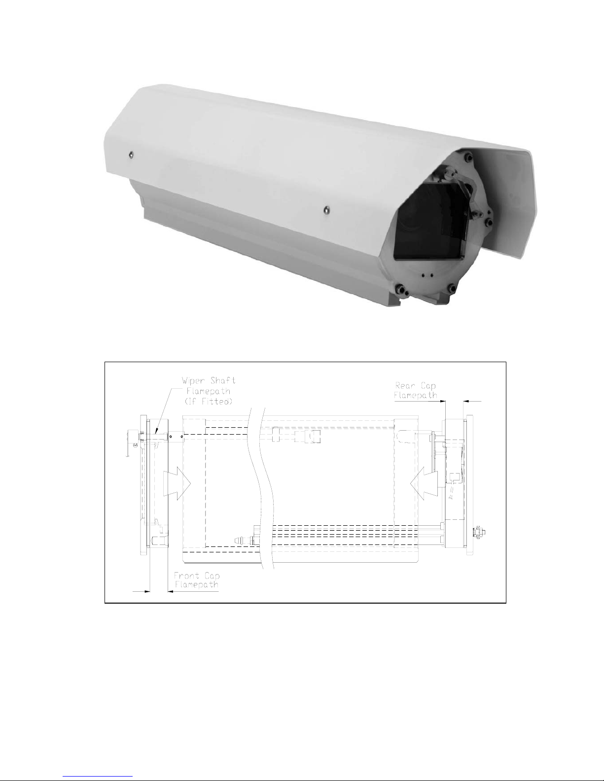
Figure 1 Typical Flameproof Camera Housing
Figure 2 Detail Showing Flame Path Zone Locations

FH07B Series Installation Instructions Issue 3.0
INS00306 Page 9 of 24
Contents of Package
The product should reach you in perfect working order. If the unit is damaged in any way or
if the supplied kit is incomplete, please contact Bewator Ltd. immediately.
1 x FH07B Series Camera Housing, including Sunshield, fitted with optional accessories.
1 x General Packing Kit comprising:
4 x M5 x 16 Hex Socket Button Head Screw.
4 x M5 Nylon Washer.
3 x M5 x 60mm M5 Hex Head Special - Rear Cap Removal Screw.
2 x M6 x 70 Cap Head - Rear Cap Fitting Guide Screw.
4 x Cable Gland (Hawke Cable Gland Type 501/421).
1 x Installation Instructions INS00306.
Optional
1 x Optional Accessories Packing Kit comprising:
Either 1 x Installation Instructions INS00054 (complete with ‘D’ Type Telemetry Module)
– 10 function Receiver [RX210].
Or 1 x Installation Instructions INS00093 (complete with ‘D’ Type Telemetry Module)
– 17 function Receiver [RX217].
Before Starting Installation
1. Ensure that the contents of the package (see above) are correct.
2. Read all of these Installation Instructions.
3. Ensure that the correct tools are used when installing – see below.
4. Ensure that the complete assembly is tested in the workshop, prior to installation on
site.
After Installation
1. Save these Installation Instructions for future use.
2. Save the 3 off Rear Cap Removal Screws and the 2 off Rear Cap Fitting Guide
Screws for future use.

FH07B Series Installation Instructions Issue 3.0
INS00306 Page 10 of 24
Suggested Tools
The following tools are suggested for the installation of a FH07B Series Flameproof Camera
Housing:
• 3mm A/F (across flats) Allen key
• 5mm A/F (across flats) Allen key
• 10mm A/F (across flats) Allen key
• No 1 ‘Posidrive’ screwdriver
• Torque wrench set to 4.5Nm
• Rubber hammer
• 8mm A/F (across flats) ring spanner
• Small flat bladed (electrical) screwdriver.

FH07B Series Installation Instructions Issue 3.0
INS00306 Page 11 of 24
Ordering the FH07B Series Unit
Certification Requirements For The Camera/Lens
To ensure compliance with the certification to the EC ‘ATEX’ Directive 94/9/EC Equipmentgroup II, Category 2, the Camera/Lens to be fitted into the FH07B Series Camera Housing
MUST adhere with the maximum requirements shown in Figures 3 and 4. Cameras and
Lenses with equal or lesser dimensions may be fitted into the Camera Housing.
Note: Fitting any of the optional accessories may restrict the size of the Camera and the
Lens that can be used.
²
Figure 3 Camera Dimensions
²
Figure 4 Lens Dimensions

INS00306 Page 12 of 24
Installing the FH07B Series Unit
Removing The Rear Cap Assembly
1. This procedure should ONLY be
performed in the workshop.
2.
NOTE: It is recommended that the
Front Cap Assembly is NOT
removed at any time.
3. Remove the Rear Cap Assembly.
a) If the Wiper Unit Kit (FH07W) is
fitted, ensure that the wiper arm
is resting in the PARK position.
(See Figure 1.)
b) Remove the 6 off M6 x 25 Cap
Head A4-80 stainless steel
screws and star washers from
around the periphery of the
Rear Cap Assembly. Retain for
future use. (See Figure 5.)
c) Screw the 3 off M5 Special Rear
Cap Removal Screws into the
special screw holes and
gradually tighten in sequence to
withdraw the Rear Cap
Assembly, maintaining an equal
gap between the Cap and the
housing Body. Initial resistance
will be provided by the ‘O’ ring
seal. (See Figure 6.)
Figure 5 Rear Cap Assembly Removal (1)
d) Withdraw the Rear Cap
Assembly (including the
Monorail) from the Body.
Note: Care should be taken to
avoid damage to the flame path
zone. (See Figure 2.)
Figure 6 Rear Cap Assembly Removal (2)
e) Remove the 3 off M5 Rear Cap
Removal Screws from the Rear
Cap Assembly and retain for
future use.

FH07B Series Installation Instructions Issue 3.0
INS00306 Page 13 of 24
Pre-installation Wiring
General
1. This procedure should ONLY be performed in the workshop.
2.
Note: Use only cable suitable for the application and that meets the standards required
by the installation.
3. Ensure that the maximum cable distances are not exceeded.
Cable Diameter Impedance Maximum Distance
0.50mm
2
50.4 Ohm/km 67 metres
0.75mm
2
32.3 Ohm/km 100 metres
1.00mm
2
19.9 Ohm/km 167 metres
4. Phoenix™ FH07B Series housings are supplied with four cable entries (M20 x 1.5
threaded) in the Rear Cap Assembly. Each threaded entry hole MUST be fitted either
with a suitable flameproof entry device (cable gland) or a stopping plug certified to the
EC ‘ATEX’ Directive 94/9/EC or local standards, where relevant.
Inside the Packing Kit (see Page 9) are supplied four off ATEX certified flameproof
cable glands which can be used by installers ONLY WHEN THE CABLE
GOING THROUGH THE GLANDS IS BETWEEN 7.5 & 11.9mm IN DIAMETER
AND IS NON-ARMOURED ELASTOMER AND PLASTIC INSULATED.
The glands are manufactured by Hawke Cable Glands Ltd., part reference
A501/421/O/M20. EC-Type Examination Certificate Number: BAS01ATEX2070X.
These glands MUST be fitted using Hawke Assembly Instructions AI307.
Suitable ATEX certified alternative glands to suit different cable specifications may also
be used, if necessary.
Any of the supplied stopping plugs (4 off normally fitted) may also be used.
5.
Note: Electrical installation methods should comply with current local and national
regulations and site regulations.
Only service personnel who are qualified to the appropriate level should carry out the
installation.
6. When connecting cables for the electrical supply ALWAYS ensure that High (mains)
voltage power conductors are separated from Low voltage (e.g. telemetry, lens, etc.) data
conductors. This will reduce potential problems that can arise through electrical noise
and interference.
7. The video cable enters the housing through one of the other cable entries, using a
suitable cable gland, and is connected directly to the Camera Video Out connector or the
(optionally fitted) Receiver.
8. An Earth Bonding Stud is provided on the outside of the Rear Cap Assembly.
9. A Terminal Block Assembly is provided to aid the electrical installation. It is securely
mounted on a Plate – Mounting, which is fixed on the Monorail.
Note: The Terminal Block Assembly is not provided with the optional 10 – function
Receiver Kit (FH07-RX210).
10. The Mains Input Cable Earth wire (E) MUST always be fitted as the primary Earth to the
internal Earth Stud. (See Figure 7.) Ensure that any factory fitted Earth wires are refitted
onto the internal Earth Stud in accordance with current local and national codes and
standards.
11. A wiring diagram for a typical configuration is provided on Page 23.

INS00306 Page 14 of 24
Wiring Requirements for FH07B Series Housings supplied WITHOUT any
optional accessories fitted
1. Confirm that the special Earth wire is
connected between the Earth Stud
on the inside of the Rear Cap
Assembly and the SUPPLY INPUT
earth (E) terminal on the Terminal
Block Assembly.
2. Confirm that the Heater cable is
connected to the HEATER (N L)
terminals on the Terminal Block
Assembly. The L wire is connected
via. the Thermostat, which is
mounted on the inside of the Rear
Cap Assembly.
3. The user supplied mains input cable
enters the housing through one of
the 4 cable entries, using a suitable
cable gland. The Earth wire (E)
MUST be connected as the primary
Earth to the Earth Stud on the inside
of the Rear Plate. (See Figure 7.)
The Live and Neutral wires are
connected to the SUPPLY INPUT (L
N) terminals (respectively) on the
Terminal Block Assembly. (See
Figure 8.)
Figure 8 Wiring Requirements (1)
Figure 7 Internal Earth Stud
Mains Input Cable
Earth Wire (E)

FH07B Series Installation Instructions Issue 3.0
INS00306 Page 15 of 24
Wiring Requirements for FH07B Series Housings supplied fitted with a Wiper
Unit Kit (FH07W Series)
1. Confirm that the special Earth wire is
connected between the Earth Stud
on the inside of the Rear Cap
Assembly and the SUPPLY INPUT
earth (E) terminal on the Terminal
Block Assembly.
2. Confirm that the Heater cable is
connected to the HEATER (N L)
terminals on the Terminal Block
Assembly. The L wire is connected
via. the Thermostat, which is
mounted on the inside of the Rear
Cap Assembly.
3. The user supplied mains input cable
enters the housing through 1 of the 4
cable entries, using a suitable cable
gland. The Earth wire MUST be
connected as the primary Earth to
the Earth Stud on the inside of the
Rear Plate. (See Figure 7.) The
Live and Neutral wires are
connected to the SUPPLY INPUT (L
N) terminals (respectively) on the
Terminal Block Assembly.
4. The Wiper control cable enters the
housing through a different cable
entry, using a suitable cable gland,
and is connected to screw terminal
10 on the Terminal Block Assembly.
(See Figure 9.)
WARNING: The Wiper control
(WIPE) wires remain at supply
voltage (even AFTER the applied
WIPE voltage is removed) until the
Wiper AUTOPARK is complete and
the microswitch is activated.
(See Figure 10.)
Figure 9 Wiring Requirements (2)
WIPER
CONTROL
(WIPE)
M
L
(PARK)
N
NC
NO
C
W
W
BR
BU
MICROSWITCH
Figure 10 Wiper Unit Kit ~ Circuit Diagram

FH07B Series Installation Instructions Issue 3.0
INS00306 Page 16 of 24
Wiring Requirements for FH07B Housings supplied fitted with a 10 - function
Telemetry Receiver Kit (FH07-RX210)
1. Note: All electrical connections to
any external equipment (e.g. a PTZ
unit) are via. the 10 - function Preset
Receiver Assembly (RX210). The
receiver is securely fitted to an
integral mounting plate fixed on the
Monorail.
2.
Note: The 10 - function Preset
Receiver offers both coaxial (“C”
Type) and twisted pair (“D” Type)
telemetry options, using plug-in
modular circuit boards, as detailed in
the Bewator Ltd. Installation
Instructions (INS00054).
3.
Note: The 10 - function Receiver
MUST be connected and tested in
accordance with the Installation
Instructions (INS00054).
4. Confirm that the special Earth wire is
connected between the Earth Stud
on the inside of the Rear Cap
Assembly and the AC INPUT earth
(E) terminal on the Receiver.
5. Confirm that the Heater cable is
connected to the AC INPUT (N L)
terminals on the Receiver. The L
wire is connected via. the
Thermostat, which is mounted on the
inside of the Rear Cap Assembly.
6. The user supplied mains input cable
enters the housing through one of
the 4 cable entries, using a suitable
cable gland. The Earth wire MUST
be connected as the primary Earth to
the Earth Stud on the inside of the
Rear Plate. (See Figure 7.) The
Live and Neutral wires are
connected to the AC INPUT (L N)
terminals (respectively) on the
Receiver. (See Figure 11.)
Figure 11 Wiring Requirements (3)

FH07B Series Installation Instructions Issue 3.0
INS00306 Page 17 of 24
Wiring Requirements for FH07B Housings supplied fitted with a 17 - function
Receiver Kit (FH07-RX217)
1. Note: The fitting of a 17 – function
Receiver Kit (FH07-RX217) creates
space limitations for the fitting of
other items into the housing, which
must be addressed. It is
recommended that the 17 – function
Receiver Kit should ONLY be fitted
to a –40 (420mm) version of the
Housing.
2.
Note: The 17 - function Receiver
Assembly (RX217) is fitted upside
down to 2 mounting brackets, which
are mounted on to 2 Plate - PCB
Mountings fixed on the Monorail.
3.
Note: The 17 - function Receiver
offers both coaxial (“C” Type) and
twisted pair (“D” Type) telemetry
options, using plug-in modular circuit
boards, as detailed in the Bewator
Ltd. Installation Instructions
(INS00093).
4.
Note: The 17 - function Receiver
MUST be connected and tested in
accordance with the Bewator Ltd.
Installation Instructions (INS00093).
Release the 4 plastic clip fasteners
from the 17 – function Receiver PCB
and turn the PCB over, placing it on
a clean workbench.
Figure 12 Wiring Requirements (4)
5. Confirm that the Heater cable is
connected to the HEATER (N L)
terminals on the Terminal Block
Assembly. The L wire is connected
via. the Thermostat, which is
mounted on the inside of the Rear
Cap Assembly.
6. The user supplied mains cable
enters the housing through one of
the 4 cable entries, using a suitable
cable gland. The Earth wire (E)
MUST be connected as the primary
Earth to the Earth Stud on the inside
of the Rear Plate. (See Figure 7.)
The L and N wires MUST be
connected to the SUPPLY INPUT (L
N) spade connectors (respectively)
on the Mains Filter unit. The Mains
Filter is securely mounted on a Plate
- Mounting which is fixed on the
Monorail. (See Figure 12.)

FH07B Series Installation Instructions Issue 3.0
INS00306 Page 18 of 24
Refitting The Rear Cap Assembly And Fitting The Sunshield
1. Refitting the Rear Cap Assembly.
Note: Before refitting the Rear Cap
Assembly, test the Camera functions
and check that the lens dust cover is
removed!
a) Take care that the ‘O’ ring seal is
free from grit and dirt. Lightly
grease the ‘O’ ring and the flame
path zone (shoulder/neck) of the
Rear Cap Assembly with clean
general purpose grease.
b) Lightly grease the ‘O’ ring and the
locating spigot at the front of the
Monorail with clean general
purpose grease.
c) Present the Rear Cap Assembly to
the housing Body, taking care to
maintain the correct rotational
alignment.
d) If the optional Wiper Unit
Kit (FH07W) is fitted:
i) Ensure that the wiper arm is
resting in the PARK position.
ii) Confirm that the rear wiper shaft
coupling is correctly aligned with
the wiper drive unit mating-half
coupling.
e) Locate the Monorail locating
spigot into the circular groove in
the bottom of the Body.
f) Slide the Monorail into the Body.
Fit the 2 off Cap Fitting Guide
Screw into a diagonal pair of fixing
holes (say 3 and 4 ) to ensure that
all the fixing holes line up. (See
Figure 13.) Partially insert the
Rear Cap Assembly into the Body
until the 6 off M6 x 25 screws can
engage. Remove the 2 off Cap
Fitting Guide Screws and retain for
future use.
Note: Care should be
taken to avoid damage to the
flame path zone. (See Figure 2.)
g) Refit the 6 off star washers and
the 6 off M6 x 25 Cap Head A4-80
stainless steel screws. Tighten
the screws evenly to a Torque
rating of 4.5Nm, in the order as
shown in Figure 14. It is essential
that only A4-80 screws be used.
Figure 13 Refitting the Rear Cap Assembly
Figure 14 Screw Tightening Sequence

FH07B Series Installation Instructions Issue 3.0
INS00306 Page 19 of 24
Figure 15 Fitting the Sunshield
2. Fitting the Sunshield.
a) Carefully place the Sunshield in
position on the Body, ensuring that
the front of the Sunshield is at the
front of the Body.
b) Fit the 4 off M5 nylon washers and
the 4 off M5 x 16 hex socket
button head screws. (See Figure
15.)
Locating The Unit
1. Please ensure that all equipment is suitable for the application and the environment for
which it is intended.
2. Please take particular care that the inter-connected equipment is fully compatible with
each other and is suitable for such use.
3. This equipment is to be installed out of reach of the user, or anyone who will come into
casual contact with the installation.
4. It is recommended that a prominent warning notice be affixed near to all moveable
Camera housing assemblies indicating that sudden unexpected movement of the
equipment may occur.
5. Be sure to provide suitable access equipment to ensure the safety of the installation or
the service personnel working on the equipment.
Mounting The Unit
1. The Camera Housing must be mounted properly and securely.
2. The Camera Housing can be mounted to a bracket, a column spacer, and a pan and tilt
(PTZ) unit or directly to a suitable structure.
3. Two sets of 4 x M6 screw mounting holes, equi-spaced on a 4” (101.6mm) p.c.d. (pitch
circle diameter), are provided on the base of the housing. It is recommended that the
rear set of 4 holes be used when cabling weighing greater than 5.0kg is connected to the
housing.
4.
Note: When attaching to a pan and tilt unit, the Camera Housing MUST be bolted directly
to the mounting surface. The use of additional spacers is NOT recommended.
5.
Note: The penetration of the 4 x M6 mounting screws into the housing mounting holes
MUST NOT exceed 13mm. It is recommended that dimensional checks be performed to
determine the correct length of the M6 mounting screws to be used for the installation.
6. As the mounting surface to which this Camera Housing could be attached is site
dependent, Bewator Ltd. does not supply fixings for securing the base of the unit to its
mounting surface. It is the responsibility of installers to ensure that fixings are selected
that are fit for the specific purpose required.
7. An appropriate disconnection device MUST be included in the installation.
8. The Ca mera Housing may be subject to remote control and therefore may move at any
time. Persons working on the equipment should take app ropriate precautions to ensure
that unexpected movement does not occur.

FH07B Series Installation Instructions Issue 3.0
INS00306 Page 20 of 24
Maintenance
The following guidelines for maintenance should be observed:
1 Month After Installation
All external fastenings and cables should be thoroughly checked for tightness, security and
wear.
6 Monthly Checks
All external fastenings and cables should be thoroughly checked for tightness, security and
wear.
Perform checks to ensure that cables are not fouling on any obstruction.
Check cables for signs of wear. Replace as necessary.
If fitted, the wiper arm and blade should be checked for wear or corrosion. Replace as
necessary.
2 Yearly Checks
If fitted, the wiper arm and blade should be replaced.
5 Yearly Checks
If the unit is exposed to very severe weather con ditions or other harsh environments , the two
‘O’ ring rubber weather seals, on the Rear Cap Assembly and on the Front Cap Assembl y,
should be replaced. The unit should be returned to Bewator Ltd. for ‘O’ ring replacement.

FH07B Series Installation Instructions Issue 3.0
INS00306 Page 21 of 24
Specifications
Mechanical
Application
Hazardous (Explosive) Atmospheres
EC Directive 94/9/EC Certification:
II 2 GD (EEx d IIB T85°C)
EN 60529 Certification: IP67
Mounting
a) Static: Wall mount using (optional) Wall Bracket, with or without
Column Spacers: e.g. BH100 + BS100
b) Moving: Pan and Tilt (PTZ) Unit: e.g. FP50B Series
FH07B-30 Series FH07B-40 Series
Dimensions
With Sunshield
Weight
Housing only
545 x 210 x 186 mm 675 x 210 x 186 mm
10.0kg 11.8kg
Temperature Range
-20 °C to +40 °C
Construction
Body: Machined aluminium extrusion
Front Cap: Machined aluminium with toughened glass window
Rear Cap: Machined aluminium with 4 off M20x15 screw gland
cable entry holes, normally fitted with stopping plugs
Finish
Body: RAL 1021 (yellow) polyester powder coat, full gloss,
textured
Front and Rear Caps: Clear anodised
Sunshield: White polyester powder coat, full gloss, untextured
Electrical
Supply Voltage
230Vac 24Vac 110Vac
Fuse
Heater/Demister
Cable Entry 1 to 4
2A 5A 2A
Thermostatically controlled to operate at a temperature 25°C
M20 x 1.5 threaded – normally fitted with Stopping Plug
4 x ATEX certified Cable Gland (Hawke Type 501/421) supplied
for use with suitable cable
Refer to Page 11 for maximum Camera/Lens specifications.

FH07B Series Installation Instructions Issue 3.0
INS00306 Page 22 of 24
Mechanical Dimensions
The physical dimensions for the FH07B Series Phoenix™ 7” Flameproof Camera Housing
are shown below. All measurements are given in millimetres.
Note: All specifications are subject to change without prior notice.

FH07B Series Installation Instructions Issue 3.0
INS00306 Page 23 of 24
Wiring Diagram
Note: These circuits are example layouts only. Refer to Bewator Ltd. for further detail.

FH07B Series Installation Instructions Issue 3.0
INS00306 Page 24 of 24
Notes
The Declaration of Conformity for this product range is available from Bewator Ltd., see
below. It is also available for download from the Bewator Ltd. web site (
www.bewator.co.uk).
Bewator Ltd.
Albany Street, Newport, South Wales, United Kingdom, NP20 5XW.
Telephone: +44 (0) 1633 821000, Fax: +44 (0) 1633 850893
Email: sales@bewator.co.uk : Internet: http://www.bewator.co.uk/
Customer Support Tel: +44 (0) 1633 820615
Whilst every effort has been made to ensure that all information contained in this document is correct at the time of publication, due to our
policy of continuous product improvement, the company reserves its right to change any information contained herein without notice.
 Loading...