

Bewator 5PQ-SM500 Users Manual

SM501 and SM501K
Contactless Smartcard
Reader Handbook
HB02/104 Iss 1A
Applicability
This handbook applies to the SM501 and SM501K Contactless
Smartcard Readers
© BEWATOR COTAG JANUARY 2000
This handbook is based on the best information available to Bewator Cotag at the time of publication.
Although every effort is made to keep our documentation up to date, small changes which arise from
the Company's policy of continuing product improvement are not necessarily incorporated. Some
products are not available in all countries. All orders are accepted only on the Company's standard
Conditions of Sale, copies of which are available on request.
Bewator Cotag, a division of Bewator Group Ltd, Mercers Row, Cambridge CB5 8EX, UK
Tel: +44 (0)1223 321535 Fax: +44 (0)1223 366799 Email: sales@bewator-cotag.com www.bewator-cotag.com


Contents
Chapter 1 Introduction
Data output .............................................................................................1-1
Reading Smartcard data...........................................................................1-1
Setting up the Reader...............................................................................1-1
Chapter 2 Installing
Mounting, connecting and setting up........................................................2-1
Chapter 3 Setting up
Jumper settings.......................................................................................3-1
Distributor Code ......................................................................................3-1
Interface 5 ...............................................................................................3-1
Data output selection (jumper JU1) ..........................................................3-2
Data type selection (JU2)..........................................................................3-3
Data output in “chip serial number” mode ................................................3-3
Interface 1 ......................................................................................3-3
Interface 2 ......................................................................................3-3
Interface 3 ......................................................................................3-3
Interface 4 ......................................................................................3-4
Interface 5 ......................................................................................3-4
Data output in “Girovend” mode...............................................................3-4
Interface 1 ......................................................................................3-4
Interface 2 ......................................................................................3-5
Interface 3 ......................................................................................3-5
Interface 4 ......................................................................................3-5
Interface 5 ......................................................................................3-5
Data output in “Cotag” mode....................................................................3-6
Interface 1 ......................................................................................3-6
Interface 2 ......................................................................................3-6
Interface 3 ......................................................................................3-6
Interface 4 ......................................................................................3-6
Interface 5 ......................................................................................3-7
LED control and BCLINK selection (JU3)...................................................3-7
LED control ....................................................................................3-7
BCLINK ..........................................................................................3-8
Chapter 4 Operation
LEDs .......................................................................................................4-1
Internal LED control .......................................................................4-1
Single wire LED control...................................................................4-1
External LED control.......................................................................4-2
All LED control modes.....................................................................4-2
Horn........................................................................................................4-2
PIN data...................................................................................................4-2
Using cards..............................................................................................4-2
Looking after a card...........................................................................4-2
i

SM501 and SM501K Contactless Smartcard Reader
Hold off time............................................................................................4-3
Repeat Data Delay (RDD)..........................................................................4-3
Chapter 5 Data output
Electrical characteristics of outputs from the Reader.................................5-1
Data Hold input.......................................................................................5-2
Wiegand interface.....................................................................................5-2
Connections.......................................................................................5-2
Electrical characteristics ....................................................................5-2
Data format .......................................................................................5-2
Card data .......................................................................................5-3
PINpad data ....................................................................................5-3
Magnetic Stripe........................................................................................5-4
Connections.......................................................................................5-4
Electrical characteristics ....................................................................5-4
PINpad data ....................................................................................5-5
Custom interfaces ....................................................................................5-5
Chapter 6 Card data format
Chip serial number mode .........................................................................6-1
Girovend mode .........................................................................................6-1
Cotag mode ..............................................................................................6-2
Information contained in a Cotag smartcard .......................................6-2
Sector type 0 - Access control.............................................................6-3
Other sector types..............................................................................6-3
ii

Chapter 1
The SM501 and SM501K Contactless Smartcard Readers are
designed to read the codes contained in “Mifare” smartcards and to
pass these codes to a host system.
The SM501K has an integrated keypad. As well as reading cards, it
also passes data entered on the keypad to the host system.
The Readers consists of a printed circuit assembly and keypad
mounted inside a plastic enclosure. They require a DC power supply.
Data output
Each Reader provides a choice of Wiegand, Mag Stripe or BCLINK
format data output for the card data (and the PIN data on the K
model).
Introduction
Reading Smartcard data
By setting a jumper, the Reader can be configured to read one of
three areas of data from the Smartcard:
• Read chip serial number from any Mifare card
• Read Girovend information only from Girovend cards
• Read Cotag information only from Cotag cards
Setting up the Reader
You configure the Reader using jumpers as desribed in chapter 2.
1-1

SM501 and SM501K Contactless Smartcard Reader
1-2
Chapter 2
Installing
Mounting, connecting and setting up
Mount the Reader in a suitable position near the door approximately
1.2m from the floor. The Reader can be installed outside in a
sheltered position.
The Reader has a mounting plate with two oval mounting holes which
are suitable for most installations - you first need to break open the
mounting holes using a screwdriver. There are also four round holes
in the mounting plate which will align with a standard wall box of the
type used, for example, for light switches.
1. If the Reader is fixed to the mounting plate, undo the four
screws which are in each corner, then place the mounting
plate in position on the wall or door frame and mark the
position of the two mounting holes. Note: the mounting plate
must be positioned with its connector at the top left.
2. Drill the two mounting holes. The holes accept 3.5mm machine
screws or No 6 wood screws.
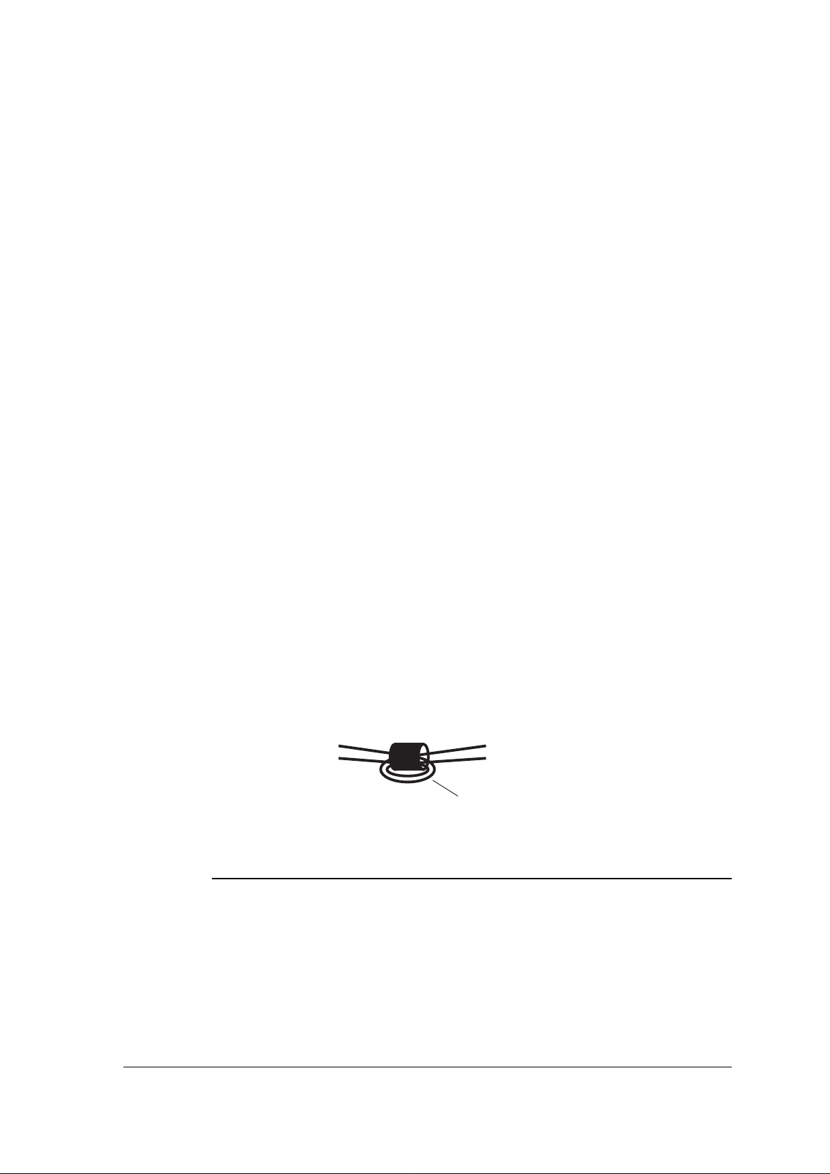
3. The connections are made to the connector on the mounting
plate. Pass the cable through the large hole in the centre of the
mounting plate. Note: the two power supply cables must be
passed twice through the hole in the ferrite bead supplied with
the Reader before they are joined to the connector, as shown in
the following diagram:
from power supply
-
+
0V
to connector on mounting plate
V+
each cable passes through ferrite bead twice
4. Make the connections shown in the following table as required:
Name Function
V+ Power supply +V (+ve) unregulated DC
max 36.0V, min 10.0V, 250mA max
0V Power supply 0V (-ve),
(also ground reference for data output)
Amber Either: Amber LED control - 0V for amber LED
Or: BCLINK data interface Rx
Horn Horn - 0V to sound
Red Either: Red LED control - 0V for red LED
Or: BCLINK data interface address
2-1

SM501 and SM501K Contactless Smartcard Reader
Name Function
Green Either: Green LED control - 0V for green LED
Or: Single wire LED control
0V for green LED, +5V for red LED
(0V also switches off amber LED)
D0 Data zero for Wiegand output
Data for Mag Stripe output
BCLINK data interface Tx
D1 Data one for Wiegand output
Clock for Mag Stripe output
DA Data Available for Wiegand or Mag Stripe output
Note: do not ap pl y a vo lta ge gre ate r than + 5 V to the horn i nput
or the LED inputs
4. Route the cable tidily, then screw the mounting plate to the
wall or door frame. Make sure all braid and loose filaments of
wire are cut right back or insulated with tape or sleeving.
5. Set the jumpers on the Reader to provide the functions you
require, as described in the following tables:
INTERFACE
Jumper JU1 Function
1 32 bit Wiegand
2 34 bit Wiegand
3 10 character Mag Stripe
4 26 bit Wiegand
5 37 character Mag Stripe
DATA
Jumper JU2 Function
1 Read chip serial number from any Mifare card
2 Read Girovend information only from Girovend cards
3 Read Cotag information only from Cotag cards
4 not used
5 not used
LED CONTROL
Jumper JU3 Function
1 Internal - LED and horn inputs are disabled
2 Single wire LED control -
0V on GREEN input for green LED,
+5V on GREEN input for red LED
3 External - LEDs and horn can be controlled using the
RED, GREEN, AMBER and HORN inputs - 0V to activate
5 BCLINK
2-2
6. Loca te the Read er on the mounti ng plate w ith the LED s at the
top left and press it home - the Reader cannot be pushed fully
home unless it is the correct way round.

Installin g
7. Tighten the screws, then insert the little plastic plugs supplied
with the Reader into the screw-holes so that the screws cannot
be seen and the case looks neat. (Note that the plastic plugs
cannot be removed without damaging them - four spare plugs
are supplied with each Reader.)
8. Power up the Reader and test it: hold a smart card close to the
outline of the card engraved on the face of the Reader - the
Reader should bleep when the card is read and the host
should receive the card data output. Each key-press should
give an amber flash and the host should receive PIN data.
2-3

SM501 and SM501K Contactless Smartcard Reader
2-4
 Loading...