

Page 1
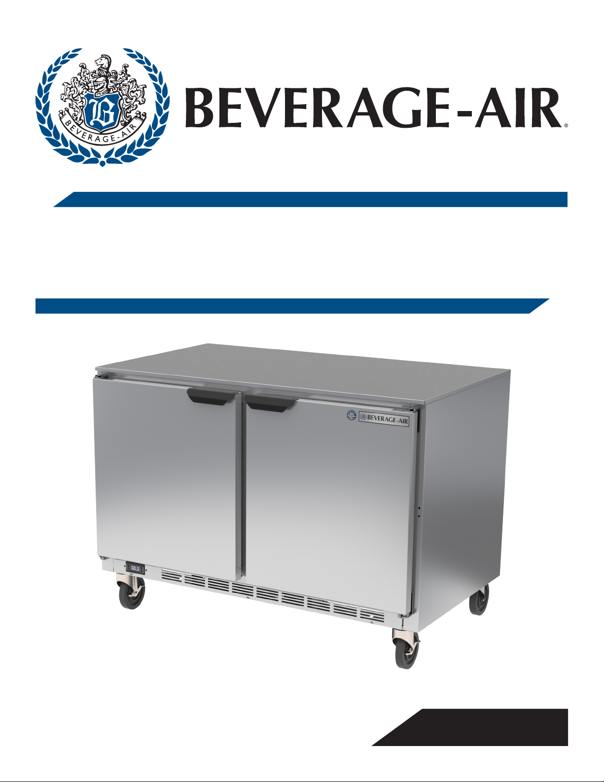
INSTALLATION AND OPERATING INSTRUCTIONS
for all
UCF Freezer Models
809-174A Rev B 10/29/2020
3779 CHAMPION BLVD, WINSTON-SALEM, NC 27105
Phone: (888) 845-9800 | Fax: (800) 253-5168 | Web: beverage-air.com
SEE BACK COVER FOR
WARRANTY REGISTRATION
Page 2

User Manual for UCF Freezers Beverage-Air
WELCOME
Congratulations on your purchase of Beverage-Air food
service equipment. Every employee welcomes you to the
family of satised Beverage-Air customers.
From the earliest stages of production design, to focused
steps in fabrication and assembly, rigid standards of
quality are maintained by our sta of skilled employees.
Beverage-Air strives to supply superior products through
strict quality control guidelines exceeding industry
standards, this means that each unit, given the proper
maintenance will provide years of trouble free experience
to its owner.
Additionally, Beverage-Air food service equipment has
one of the best warranties in the food service industry,
and backed by a professional sta of service technicians
across the country.
We thank you for your choice and condence in BeverageAir Equipment.
For part inquiries or orders please call our Technical
Service Department at (800) 684-1199. 8:00 AM to 5:00
PM EST.
Important Information
• PLEASE READ THESE INSTRUCTIONS CAREFULLY
BEFORE INSTALLING OR USING, IF RECOMMENDED
PROCEDURES ARE NOT FOLLOWED, WARRANTY
CLAIMS MAY BE DENIED.
• Your warranty registration information is located with
this manual. Please complete the card and submit it to
Beverage-Air within TEN days of installation. Failure
to properly register equipment may limit or void the
warranty.
Contents
Safety ........................................................................................................................................................................ 3
• Beverage-Air reserves the right to change
specications and product design without
notice. Such revisions do not entitle the buyer to
corresponding changes, improvements, additions, or
replacements for previously purchased equipment.
Important Information .......................................................................................................................................... 4
Product Information .............................................................................................................................................. 5
Clearance and Placement ..................................................................................................................................... 6
Unpacking and Set Up ............................................................................................................................................7
Shelf Installation ..................................................................................................................................................... 8
Electrical ................................................................................................................................................................... 9
Using The Unit ........................................................................................................................................................10
Sequence of Operations Freezer ........................................................................................................................ 11
Cleaning and Maintenance .................................................................................................................................16
Drawer Cleaning and Maintenance ..................................................................................................................17
Condenser Cleaning ...............................................................................................................................................18
Methods For Cleaning Stainless Steel..............................................................................................................19
Help ..........................................................................................................................................................................20
For The Service Tech - R290 ..............................................................................................................................21
For The Service Tech - Wiring Diagram ........................................................................................................... 22
Limited Warranty .................................................................................................................................................23
Limited Warranty (continued) ...........................................................................................................................24
Rev. 10/20Beverage-Air2
Page 3
User Manual for UCF Freezers Beverage-Air
SAFETY
This appliance has been designed with your safety in mind. It has many features to keep you from being harmed. However,
safe operation and maintenance are your responsibilities.
CAUTION
Use: When using this unit, please:
• Move it carefully. If on casters be sure the casters do
NOT run over the power cord.
• Lock the casters when in use.
• Seek help. This machine is heavy! Be sure to move
with enough help to avoid tipping or dropping the
cabinet.
CAUTION
Maintenance
Do NOT:
• Clean a frozen evaporator with a sharp object
• Clean a dirty condenser with a sharp object.
• Store gasoline, kerosene or any other ammable
material near the cabinet.
Important Information to Add
• Prevent children from playing in or on the cabinet.
Persons unable to use this product must be
prevented access.
• Follow all instructions. There are many safety labels
and directions on the unit. Heed them.
• Watch your ngers. There may be pinch points near
the door hinges.
Do ALWAYS
• Use a Beverage-Air recommended technician certied
to repair R290 equipment.
• Use ONLY Beverage-Air factory service parts. Use of
non OEM parts can be dangerous because of the design
changes needed to safely use R290.
Record the model number, serial number and the date of installation here for future reference. The model and serial
numbers are on the unit's serial number dataplate, which is located on the left inside wall.
Model Number
Serial Number
Date of Installation
Purchased From
Observe the Caution and Warning notices. They are indicators of
CAUTION
Rev. 10/20 Beverage-Air 3
WARNING
important safety information. Keep this manual for future reference.
Page 4
User Manual for UCF Freezers Beverage-Air
IMPORTANT INFORMATION
This unit is intended to be used in a commercial application. That includes schools and cafeterias.
If installed in a residence some commercial service companies may not be able to service it on site.
The manufacturer has designed and produced this machine with the nest in materials. The manufacturer assumes no
liability for units that have been altered in any way. Alterations or part substitutions will void the warranty.
Limitations
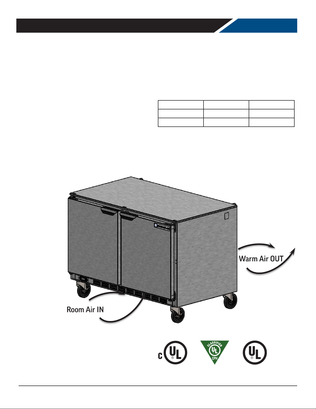
The machine is designed for use indoors in a controlled
environment. It must be kept dry, not overheated or
subjected to excessive cold. May only be connected to
a dedicated electrical circuit. Extension cords are not
permitted.
Voltage 103.5 126.5
Room Air Temp 60º F 100º F
Air Flow, All Models regardles of section, drawer count or drawer material.
Minimum Maximum
Agency Approvals
These marks appear on the dataplate or serial tag, located
in the inside of the left wall. The dataplate also contains
the model and serial numbers as well as electrical
requirements.
Rev. 10/20Beverage-Air4
Page 5
User Manual for UCF Freezers Beverage-Air
PRODUCT INFORMATION
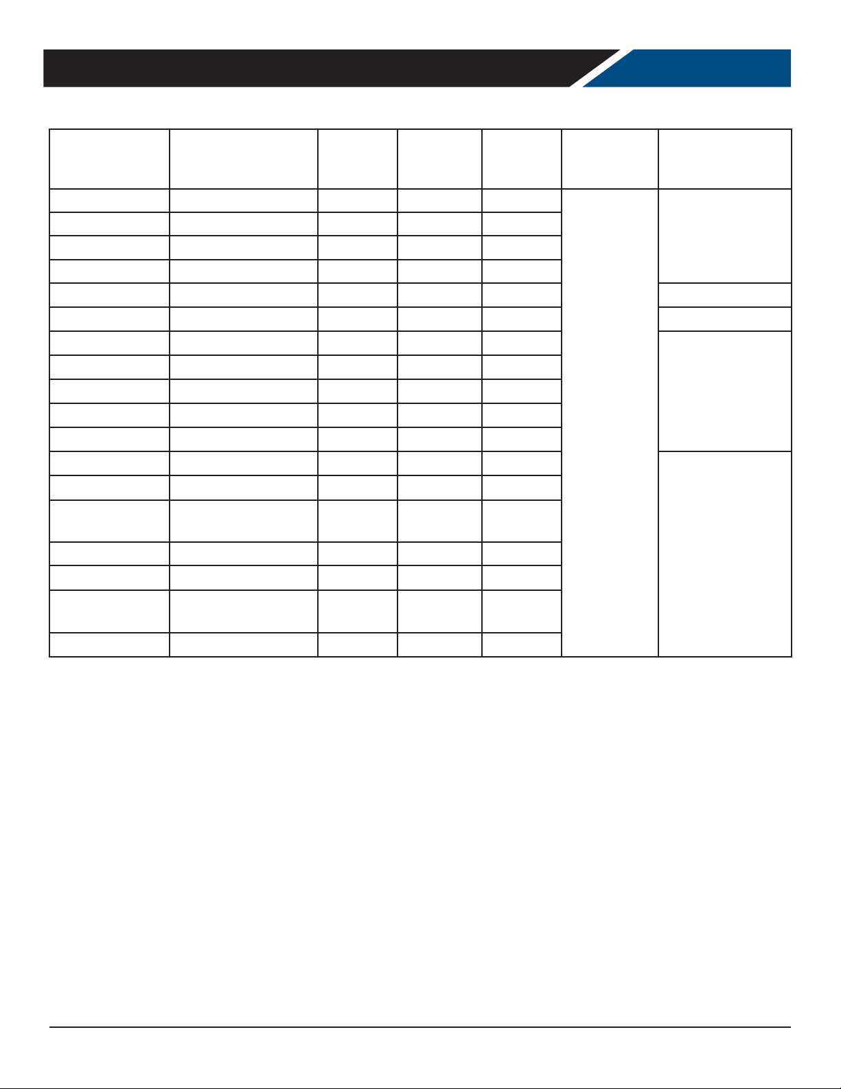
Model
UCF20HC 20 x 24 1/2 x 31 1/8 Solid 1 2.5
UCF24AHC 24 x 32 x 34 5/8 Solid 1 2.5
UCF27HC 27 x 29 7/8 x 34 5/8 Solid 1 2.5
UCF27AHC 27 x 32 x 34 5/8
UCF27AHC-25 27 x 32 1/2 x 34 5/8 Glass 1 2.5 R-290 / 55 / 1.94
UCFD27AHC 28 x 32 x 34 5/8 Solid 2 Drawers 2.5 R-290 / 45 / 1.59
UCF32AHC 32 x 32 x 34 5/8 Solid 1 4
UCF32AHC-25 32 x 32 5/8 x 34 5/8 Glass 1 4
UCFD32AHC 32 x 32 x 34 5/8 Solid 2 Drawers 4
UCF36AHC 36 x 32 x 34 5/8 Solid 2 5.2
UCFD36AHC 36 x 32 x 34 5/8 Solid 2 Drawers 5.2
UCF48AHC 48 x 32 x 34 5/8 Solid 2 7
UCF48AHC-25 48 x 32 1/2 x 34 5/8 Glass 2 7
UCFD48AHC-2 48 x 32 x 34 5/8 Solid
UCFD48AHC-4 48 x 31 7/8 x 34 5/8 Solid 4 Drawers 7
Cabinet Dimensions
w x d x h (Inches)
Door Type
Solid 1 2.5
Door or
Drawer
Count
2 Drawers,
1 Door
Full Load
Amps
7
Power Cord
Plug (NEMA)
5-15P
Refrigerant Type /
Charge (g) / (oz)
R-290 / 45 / 1.59
R-290 / 75 / 2.65
R-290 / 110 / 3.9
UCF60AHC 60 x 32 x 34 5/8 Solid 2 7
UCFD60AHC-2 60 x 32 x 34 5/8 Solid
UCFD60AHC-4 60 x 32 x 34 5/8 Solid 4 Drawers 7
2 Drawers,
1 Door
7
Height includes casters.
• Maintains 0oF and below.
• ALWAYS REFERENCE YOUR EQUIPMENT DATA PLATE AMPS, REFRIGERANT AND REFRIGERANT CHARGE FOR THE
MOST UP TO DATE AND ACCURATE VALUES.
• There are no access valves on the refrigeration system.
Rev. 10/20 Beverage-Air 5
Page 6
User Manual for UCF Freezers Beverage-Air
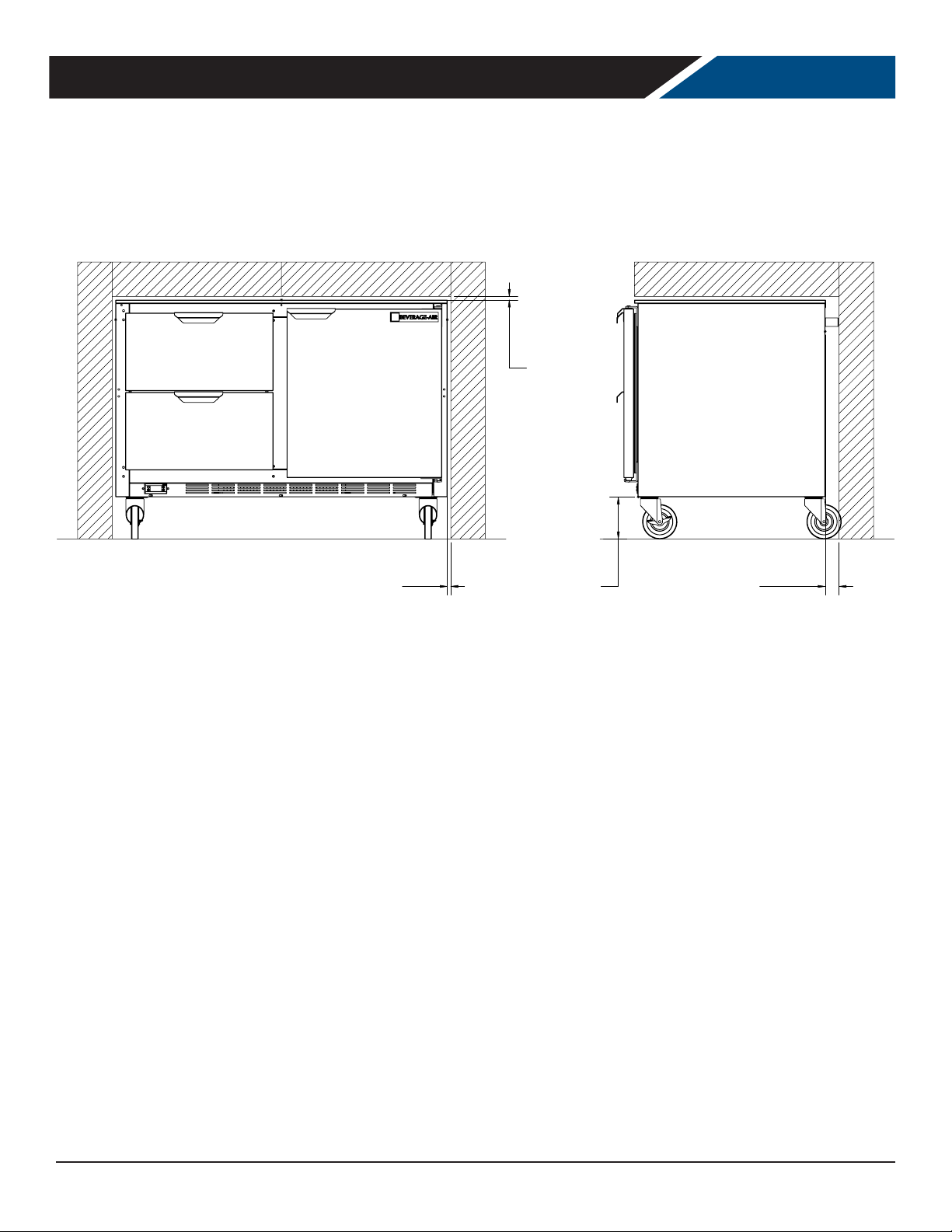
CLEARANCE AND PLACEMENT
0"
TOP
MINIMUM
CLEARANCE
0"
LEFT/RIGHT SIDE
MINIMUM
CLEARANCE
Placement
Consider the following when selecting a location for your freezer:
Clearance:
• 0 in. at the top
• 2.0 in. at the rear,
• 0.0 in. at the left side
• 0.0 in. at the right side
• 3 in. below
3"
BOTTOM
MINIMUM
CLAERANCE
2"
REAR
MINIMUM
CLEARANCE
Floor Load: the oor on which the freezer is located must be even and level, free from vibrations, and strong enough to
support the combined weights of the unit and maximum product load.
Ventilation: Grill area at front must be free and clear of any object or wall.
Power Outlet: Dedicated power outlet is located within 8 feet of length of cord.
Rev. 10/20Beverage-Air6
Page 7
User Manual for UCF Freezers Beverage-Air
UNPACKING AND SET UP
Carefully inspect the shipping carton for damage. This is the only time that shipping damage may be claimed. If damage is
suspected, open the carton immediately and, if there is damage, retain the carton and contact the shipper to make a claim.
Do NOT contact the manufacturer.
Uncrating
Tools Needed: ¾” box wrench, adjustable wrench, level,
at head screw driver, and box cutter.
1. Remove the cardboard top capping, all clear tape,
and all staples including those at the bottom of the
cardboard carton and skid.
2. Start from the top of the carton. Using the box cutter,
carefully make one continuous cut to the bottom of
the skid. Remove cardboard carton and discard.
Skid Removal and Caster Attachment
Tip the unit forward and remove the skid.
WARNING
Risk of personal injury.
Unit must be securely supported
while attaching casters or legs.
1. Remove the shipping bolts using the ¾” box wrench
while cabinet is held in one direction. Repeat the process
while the cabinet is held in the opposite direction.
2. None of the threads on the leg or caster stem should
be visible once screwed in.
3. Tilt the cabinet in one direction approximately 8” and
block it securely with pieces of 2x4 lumber or other
Note: additional clear plastic protective wrap is
applied directly to any product with a glass door.
3. Move unit as close to nal position as possible before
removing the skid.
Note: The skid must be removed before the casters or
legs can be attached.
Do NOT tip unit on its front or sides. If tipped onto the
back, unit must not be started for 3 hours.
suitable material.
4. Thread the stem casters or legs into the ½ -13 holes in
the bottom of the cabinet. Tighten by hand as much
as possible.
5. Once the caster or leg cannot be turned any further,
use a 3/4 inch wrench to tighten the nut in between
the mounting plate and the wheel of the caster until
snug.
6. Repeat this procedure with unit secured in the
opposite direction so as to access the remaining legs/
casters
7. If plate casters or legs are installed instead of stem
casters or legs, then repeat step 3 above and secure
the plate with either #14 AB screws, or ¼-20 screws,
depending upon which are required.
Leveling:
Cabinets must be leveled when installed. Level should be
measured on the headrail.
Failure to level your cabinet may result in door not
sealing, closing correctly, or condensed water draining not
draining properly.
For cabinets with legs, rotate the foot of the leg with an
adjustable wrench to achieve desired height for leveling.
For cabinets with casters, leveling can be achieved by
placing large washers in between the ½’ stud and the
Rev. 10/20 Beverage-Air 7
holes located on the bottom of the case.
Do NOT loosen casters to level
the cabinet. Casters MUST be
CAUTION
Install or attach any accessories that will be used
Remove any plastic covering the stainless steel.
tightly secured to cabinet for full
strength.
Page 8
User Manual for UCF Freezers Beverage-Air
SHELF INSTALLATION
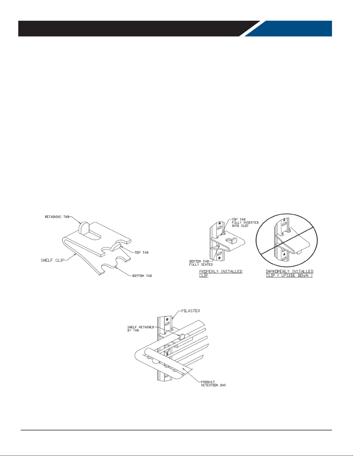
1. Determine the proper location for the shelf clips.
The reference numbers on the pilaster can serve as a
guide to ensure all clips are properly located.
2. Insert the top tab of the shelf clip into the desired
hole of the pilaster. The retaining tab MUST be facing
up as shown.
3. Rotate the clip downwards and insert the bottom tab
into the matching hole in the pilaster. The clip may
need to be squeezed slightly during installation.
4. Install all remaining clips.
5. Install shelves onto clips with the product retention
bar facing up. Be careful not to dislodge clips during
installation.
6. Place shelves so that the retaining tab on the clip
captures the shelf as shown.
7. Conrm that the shelf is resting on ALL 4 clips and
that the clips are securely attached to the pilasters.
8. Improper shelf clip installation could cause the shelf
and / or the product on it to fall, resulting in damage
to the unit and possible bodily injury.
9. Do NOT overload the shelves. The unit is designed to
use all shelves that are supplied in an equally spaced
manner. Contact Beverage-Air customer service if
fewer shelves or a dierent conguration to ensure
shelf overloading will not occur.
Rev. 10/20Beverage-Air8
Page 9
User Manual for UCF Freezers Beverage-Air
ELECTRICAL
This is a cord-connected unit, and must be connected to its own dedicated power supply. Check the dataplate on the
machine to conrm the voltage and per the dataplate use the correct fuses or HACR circuit breakers.
Note: Do not connect to GFI / GFCI outlets. Connection to that type of outlet can result in product loss due to
unsafe cabinet temperature when GFI device trips from moisture.
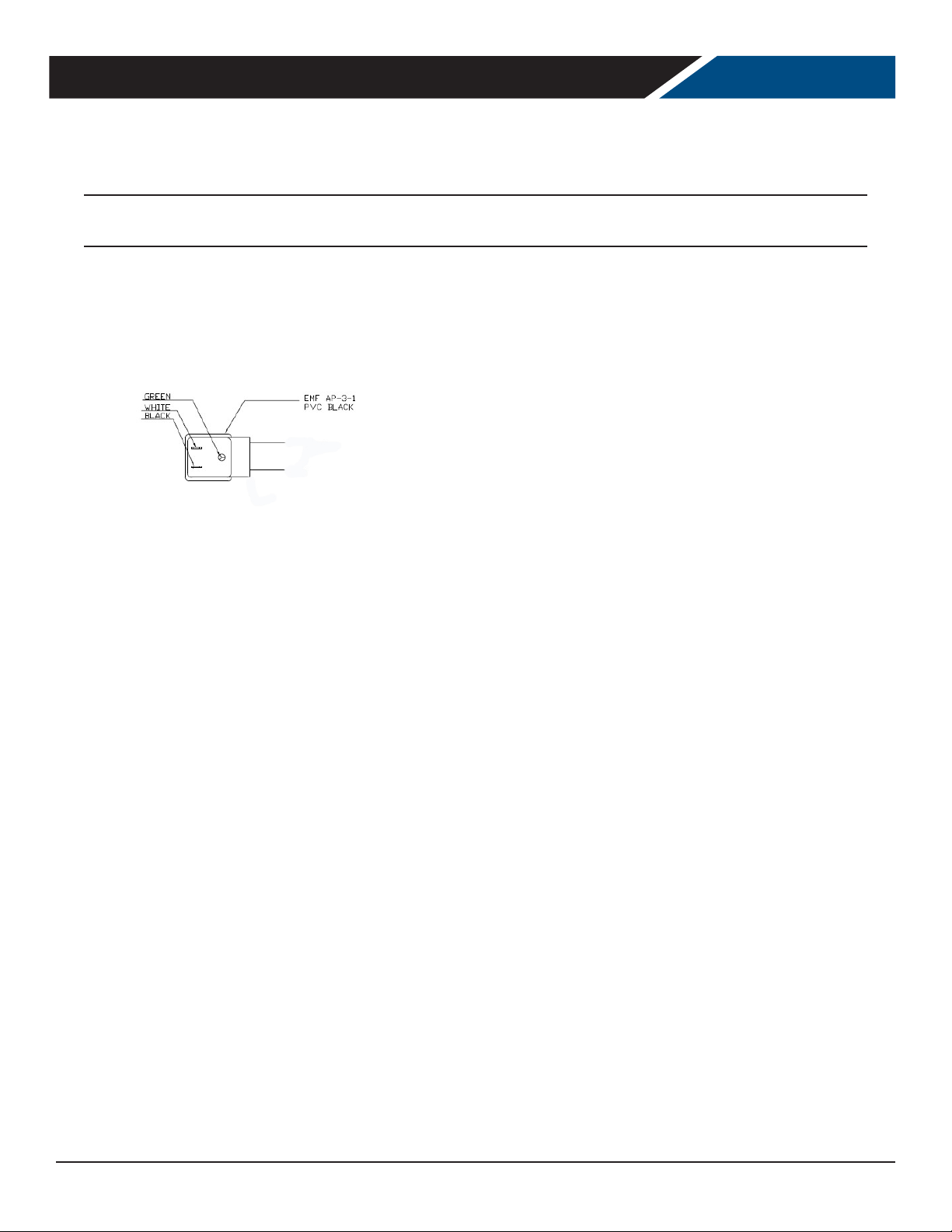
Power Cord
This 115 volt model is equipped with a cord and a 5-15P plug.
5-15P
If the power cord becomes damaged, it must be replaced
with the identical cord.
Follow All National and Local Codes
This unit must be grounded. Do not use extension cords
and do not disable or by-pass ground prong on electrical
plug.
Initial Start Up
Plug the power cord into the proper power supply.
Door Reversal Instructions
1. Remove hinge cover
2. Remove door from the unit to include the hinge
mounting brackets
3. Remove white hole covers from the side of the door
opening you would like the hinges to be located (do
not throw away)
4. On the bottom of the door the same hole plugs are
present and need to be removed
5. Take the hole plugs and insert them into the screw
holes where the hinges were originally located on the
unit
6. Install the hinge bracket upright on the unit. The
thick portion of the hinge bracket should be on the
bottom as you mount them
7. The door portion of the hinges need to be removed
and rotated 180 degree and remounted
The cabinet will soon begin to blow warm air out of the
top area, and cool air will ow from the inside blower.
The cabinet temperature has been set at the factory and
should not need adjustment, however if it was changed,
the standard setting is 0º F.
Cautions
Care must be taken whenever moving or servicing the
unit. The refrigerant is contained in a sealed system, but if
released it may be ammable.
Rev. 10/20 Beverage-Air 9
8. Install the hole plugs that were removed from the
bottom of the door into the holes where the handle
was rst mounted
9. Install the handle on what is now the top of the door
10. Slide door back into position and gently lower into the
white pivot cam
11. Replace hinge cover
Page 10
User Manual for UCF Freezers Beverage-Air
USING THE UNIT
Operation is simple, just keep it connected to the correct
power supply and the freezer will maintain the internal
temperature it has been set to. Keep the drawers closed as
much as possible to avoid unnecessary run time.
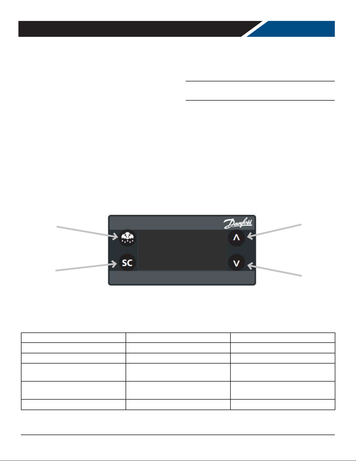
The controller displays the current internal temperature.
Adjusting the set temperature lower will NOT cause the
system to lower the temperature faster. When on, the
refrigeration system is always operating at maximum.
The temperature was set at the factory at 0º F, but you can
adjust it to your own selected temperature. 30 seconds
after adjustment, the display automatically reverts to
showing the current temperature.
Defrost
The freezer will automatically defrost as needed, there is
no set time for defrost. Push and immediately release the
"melting" or defrost button for a manual defrost.
Note: Holding the defrost button in too long will shut the
controller o.
The internal fan will be on when the compressor is on and
when the doors are closed.
The compressor and condenser fan motor will only be on
when the controller senses an increase in internal cabinet
temperature passed the set point.
If equipped with glass doors, holding the SC button in will
turn the cabinet light on or o.
Increase
o
F
0
Select
In most cases the only thing displayed will be the cabinet temperature. When something other than normal operation has
occurred, a message will be shown.
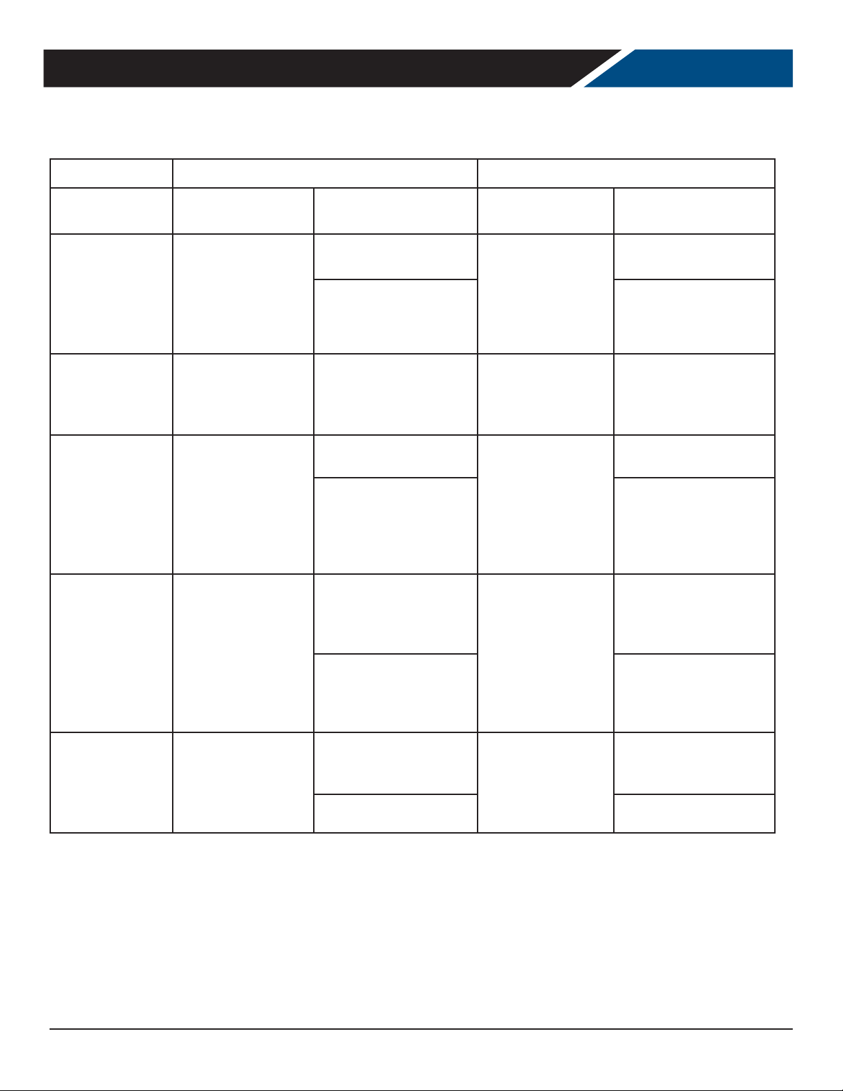
Message Displayed Why What to do
dEF
Hi
dOr
LEA
E01, E02, E03, E04
Unit is defrosting Nothing. Normal operation.
Cabinet temperature too warm Conrm doors or drawers are closed.
Door is open Close door, if message does not
Compressor run time too long Check doors closed. If yes, call for
Sensor unplugged or has failed Call for service.
Decrease
change, call for service.
service.
Rev. 10/20Beverage-Air10
Page 11
User Manual for UCF Freezers Beverage-Air
SEQUENCE OF OPERATIONS FREEZER
The freezer operates based on the air temperature measured by the probe located at the return air.
ON OFF
COMPONENT OPERATION
Compressor turns
on when the air
COMPRESSOR
CONDENSER FAN
EVAPORATOR
FAN
DEFROST HEATER
FACE/DOOR
HEATERS
temperature at the
probe is above the
sum of the set point
+ 2.5
The Condenser
Fan turns on when
the Compressor is
running
The Evaporator
Fan turns on when
the Compressor is
running and the
doors are closed.
The Defrost Heater
will activate
on cumulative
Compressor runtime
of 6 hours, and when
temperature drops
too low
The Face & Door
Heaters turn
on when the
Compressor is
running
CONTROLLER
ACTION
The Compressor Contact
is energized
(ERC 112 - Terminal #1) (ERC 112 - Terminal #1)
The Condenser Fan is
wired directly to the
Compressor, not through
the controller
The Evaporator Fan is
wired to the Fan Contact
(ERC 112 - Terminal #5) (ERC 112 - Terminal #5)
The Defrost Heater
Contact is energized
(ERC 112 - Terminal #6) (ERC 112 - Terminal #6)
The Door/Face Heater
are wired to the
Compressor Contact
(ERC 112 - Terminal #1) (ERC 112 - Terminal #1)
OPERATION
Compressor turns
o when the air
temperature at
probe is equal to
or less than the set
point – 2.5
The Condenser Fan
turns o when the
Compressor is not
running
The Evaporator Fan
turns o when the
Compressor is not
running, and when
door is opened
while Compressor is
running
When either the
defrost is not
scheduled or the
temperature at
defrost probe
has reached the
defrost termination
temperature.
The Face & Door
Heaters turn
o when the
Compressor is not
running
CONTROLLER
ACTION
The Compressor Contact
is de-energized
The Condenser Fan is
wired directly to the
Compressor, not through
the controller
The Evaporator Fan is
wired to the Fan Contact
The Defrost Heater
Contact is de-energized
The Door/Face Heater
are wired to the
Compressor Contact
Rev. 10/20 Beverage-Air 11
Page 12
User Manual for UCF Freezers Beverage-Air
Condition
Compressor
Condenser
Fan
Evaporator
Fan
Defrost
Heater
Face/Door
Heater
Drain Heater
Cabinet Temp > Set point + 2.5 ON ON ON OFF ON ON
Cabinet Temperature <= Set point - 2.5 OFF OFF OFF OFF OFF ON
Defrost OFF OFF OFF ON OFF ON
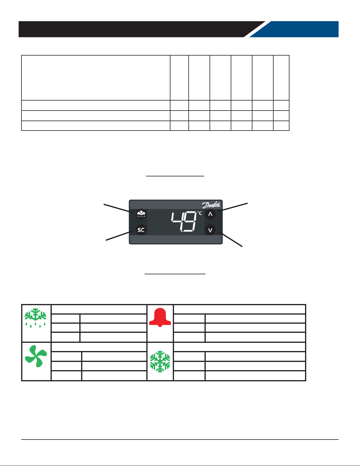
Electronic Controller
DEFROST (ESC)
UP
SELECT (OK)
DOWN
Control Panel Display
Defrost LED Alarm LED
On xed: Defrost active On xed: ALARM Present
O: Defrost is o Flashing: ALARM Silenced
O: No Alarm
Fan LED Compressor LED
On xed:
O:
Fan active
Fan O
On xed: Compressor active
Flashing: Delay, protection or activation blocked
O: No Alarm
NOTE: When switched on, the instrument panel performs a lamp test for a few seconds.
Rev. 10/20Beverage-Air12
Page 13
User Manual for UCF Freezers Beverage-Air
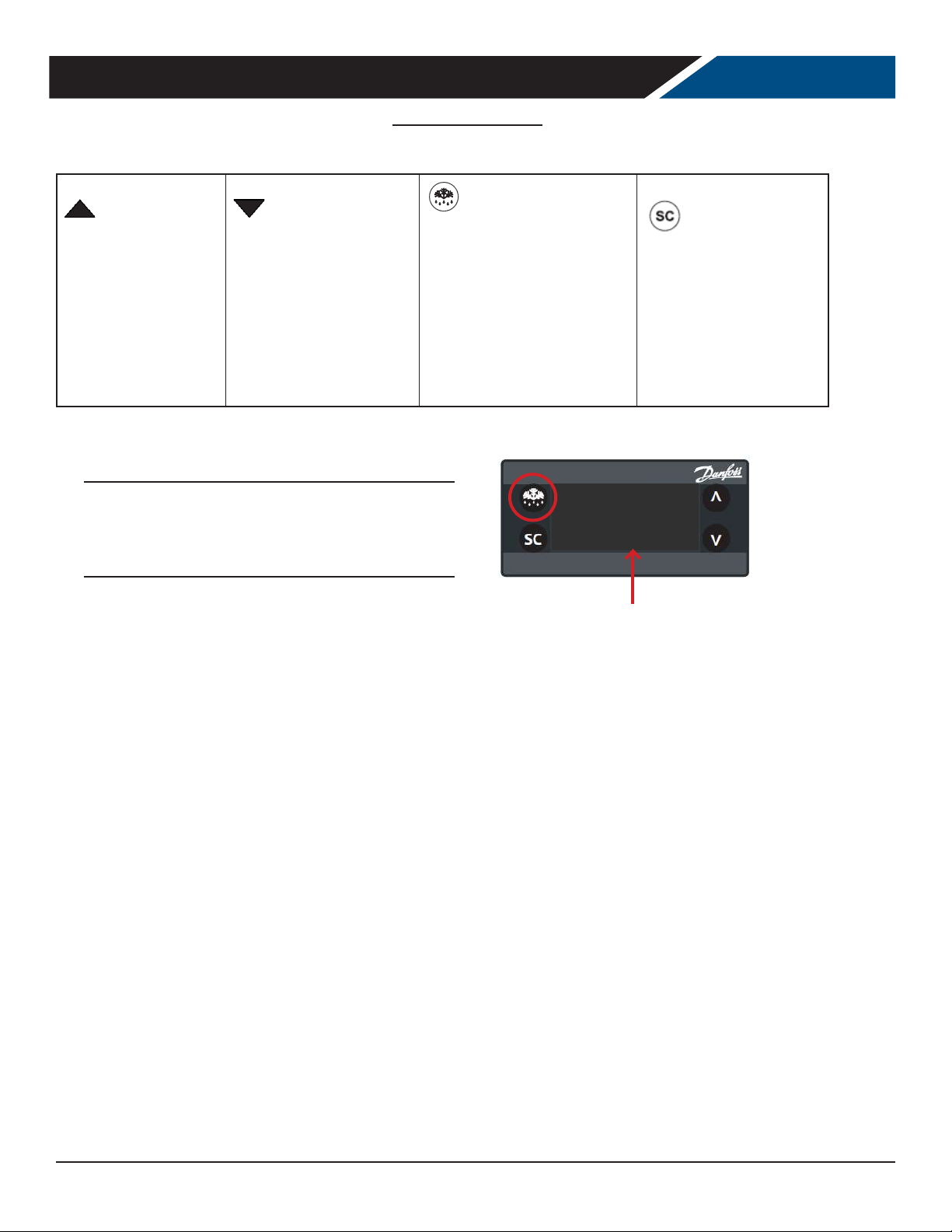
Keyboard Functions
UP
Quick press and release
•
Increases Set Point
Long press and release
•
Increases display brightness
DOWN
Quick press and release
•
Decreases Set Point
Long press and release
•
Decreases display brightness
Note: When the controller is in a Standby Mode, a
blue dot will be displayed as shown here. To switch
out of Standby Mode, push and hold the Defrost
button until the display reads ON.
DEFROST (ESC)
Quick press and release
•
Activates manual defrost
Long press and release
•
Controller enter stand-by mode
SET (ENTER)
Quick press and release
•
Toggles lights on/o
Long press and release
•
Toggles display °F/°C
.
Rev. 10/20 Beverage-Air 13
Page 14
User Manual for UCF Freezers Beverage-Air
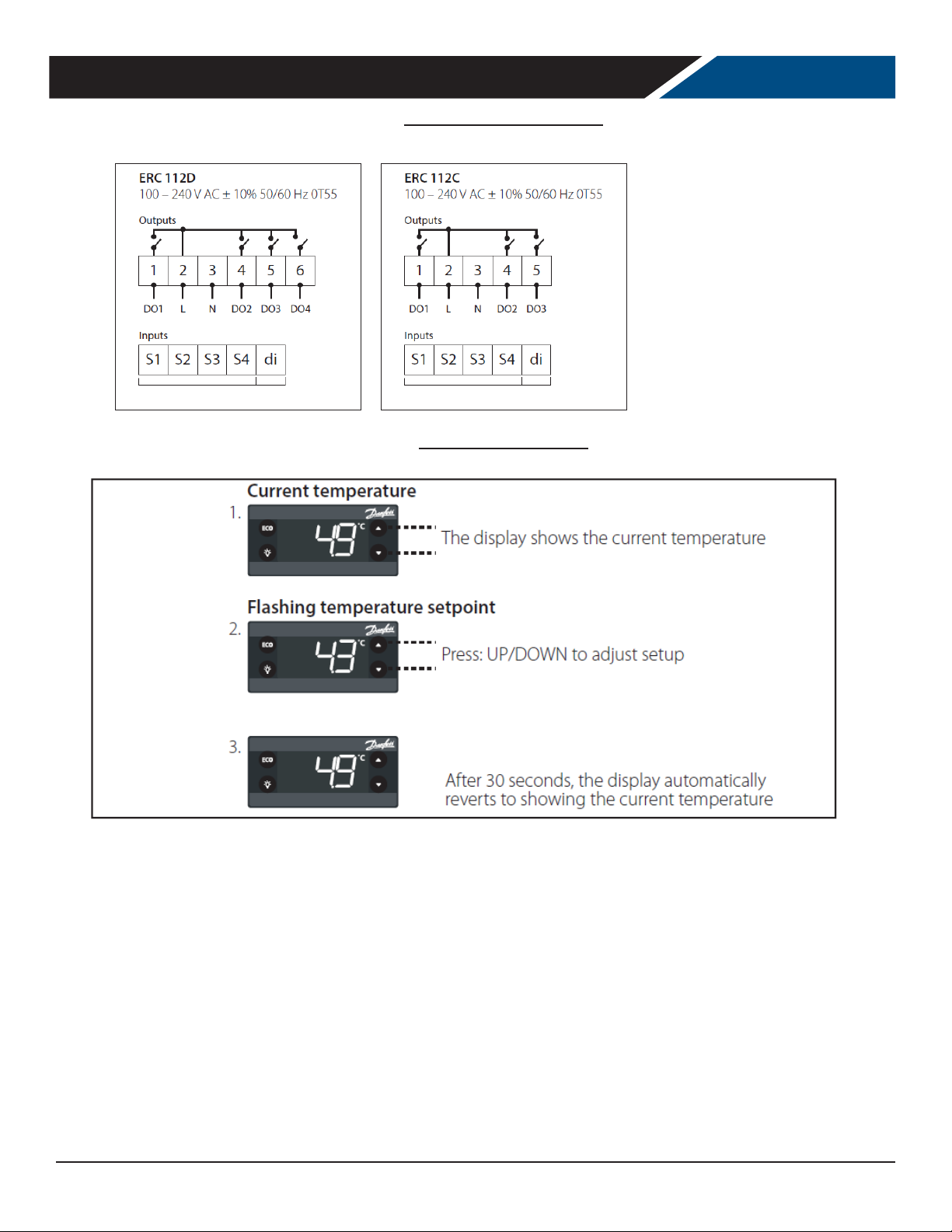
Control Panel Connections
Changing the Set point
Rev. 10/20Beverage-Air14
Page 15
User Manual for UCF Freezers Beverage-Air
Keyboard Functions
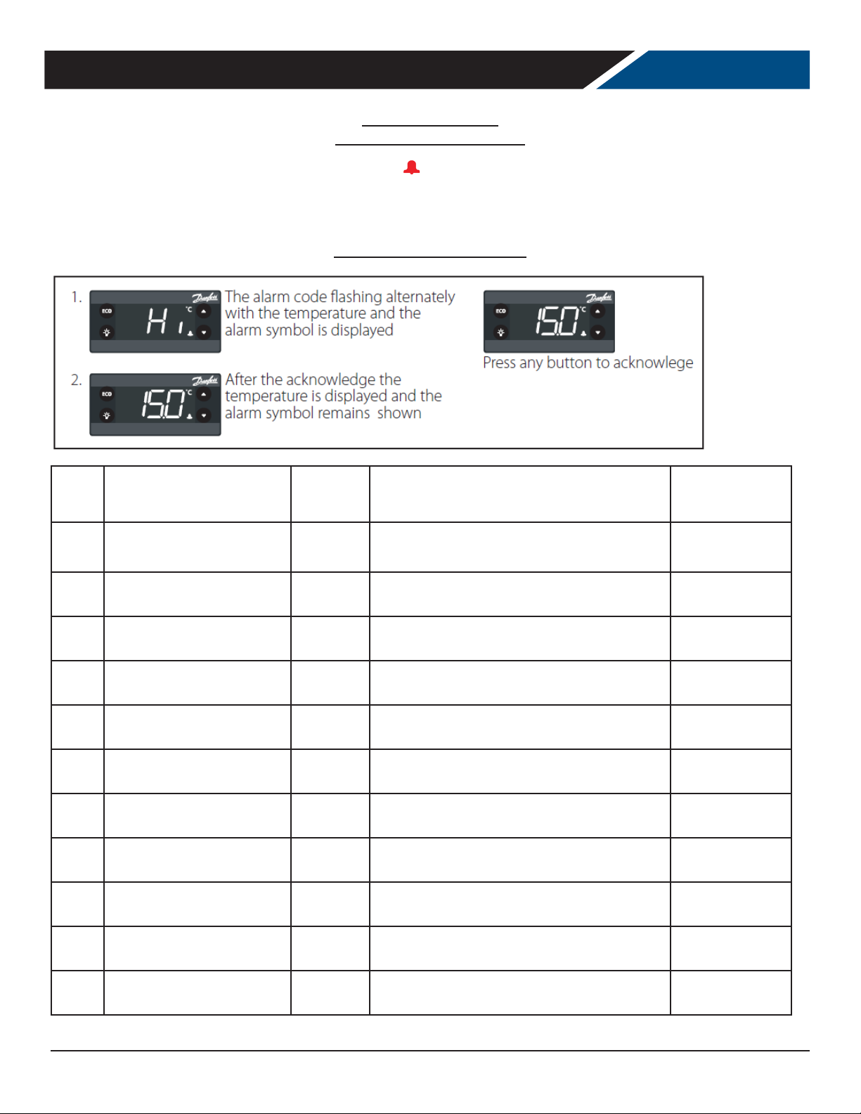
The alarm condition is always signaled by the alarm icon . To turn o the relative icon will continue ashing.
NOTE: If alarm exclusion times are in progress (ALA folder of the parameter table), the alarm is not signaled.
Electronic Controller Alarms
How to Acknowledge Alarms
Alarm
Code
"Hi" Air temperature is higher than
"Lo" Air temperature is lower than
"Con" Condenser temperature is too
"dor" Door open for more than Always Blink "dor". If congured: cut in alarm relay, beep the
"uHi" Line voltage is higher than "Cop-
"uLi" Line voltage is higher than "Cop-
"LEA" Compressor cont inuous running
"E01" "S1" error Always Blink "SOl ". lf congured: cut in alarm relay, beep the
Trigger Automatic
Clearance
User
"ALA->Hat• for "ALA->Htd"
"LAt" for "Ltd''
high or too low
>uHi"
>uLi"
for more than "ALA->LEA"
congured
User
congured
User
congured
Always Blink "uHi". If congu red: cut in alarm relay, beep the
Always Blink "ulo". If congured: cut in alarm relay, beep the
Always Blink "LEA". If congured: cut in alarm relay, beep the
Outputs Comments
Bl ink "Hi" with the highest temperature; If
congured: cut in alarm relay, beep the buzzer
Blink "Lo" with the lowest temperatu re. If
congured: cut in alarm relay, beep the buzzer
Blink "Con". If congured: cut in alarm relay, beep the
buzzer
buzzer
buzzer
buzzer.
buzzer
buzzer
High temperature
alarm
Low temperature
alarm
Condenser alarm
Door open alarm
High voltage alarm
Low voltage alarm
Leakage alarm
"S1" sensor failure
(short or open)
"E02" "S1" error Always Blink "SO2". lf congured: cut in alarm relay, beep the
buzzer
"E03" "S1" error Always Blink "S03 ". lf congured: cut in alarm relay, beep
the buzzer
"E04" "S1" error Always Blink "SO4 ". lf congured: cut in alarm relay, beep
the buzzer
Rev. 10/20 Beverage-Air 15
"S2" sensor failure
(short or open)
"S3" sensor failure
(short or open)
"S4" sensor failure
(short or open)
Page 16
User Manual for UCF Freezers Beverage-Air
CLEANING AND MAINTENANCE
Cleaning Schedule:
Cabinet
Daily wipe down
Weekly interior
Condenser coil
Quarterly cleaning
Gaskets
Daily inspection, check
that hinges are tight to
the cabinet.
Daily Exterior Cleaning
It is much easier to clean on a regular basis than to have to remove stains once they have built up.
1. Wash with a clean sponge and a mild detergent that
does not contain chlorine.
2. Rinse with clean water.
3. Dry with a soft cloth.
4. Polish with a soft cloth, wiping with the grain.
5. Wipe weekly with stainless steel cleaner.
Weekly Interior Cleaning
1. Remove all food, food related items and shelves. Store
the food at a safe temperature.
2. Disconnect power to the unit (unplug it or switch the
breaker o).
scrub brush.
5. Rinse with clean water and allow to air dry.
6. Return the shelves to the unit and secure them.
Routine maintenance
Annually
3. Remove all loose food particles from the inside walls,
oor, door liner and ceiling.
4. Scrub all interior surfaces and door gaskets with a
warm (100oF to 110oF) detergent solution and a soft
7. Restore power.
8. Return food to the unit when it has reached a safe
temperature.
Rev. 10/20Beverage-Air16
Page 17
User Manual for UCF Freezers Beverage-Air
DRAWER CLEANING AND MAINTENANCE
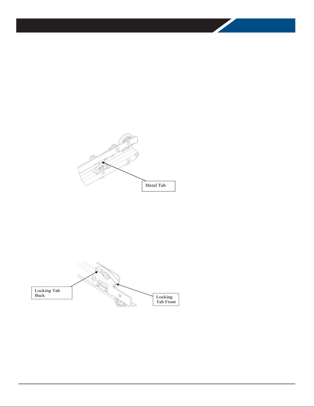
Drawer models are shipped with the drawers already installed in the cabinets. Drawers are designed with slides which
have locking mechanisms to prevent drawers from coming o cabinets during normal opening and closing operations.
See illustration below:
Drawers and slides can be removed from a cabinet for cleaning purposes. To remove a drawer from a cabinet follow these
instructions:
1. Open the drawer to full extension
2. Push the white locking tabs forward on both sides of the drawer
3. Press down the back of the tabs
4. Slide the drawer out of the cabinet
5. To remove the sliding member (Middle slide), press the metal tab up and slide it 6 - To reinstall the sliding member,
press the metal tab up and slide it in
6. To reinstall drawer, push the locking tab forward and press the back of the tab down 8 - Align the drawer slide
members and moving slide members
7. Slide the drawer in and lock the slide by pushing the front of the locking tab down and in
Rev. 10/20 Beverage-Air 17
Page 18
User Manual for UCF Freezers Beverage-Air
CONDENSER CLEANING
Keeping the condenser coil clean is critical to ecient
operation.
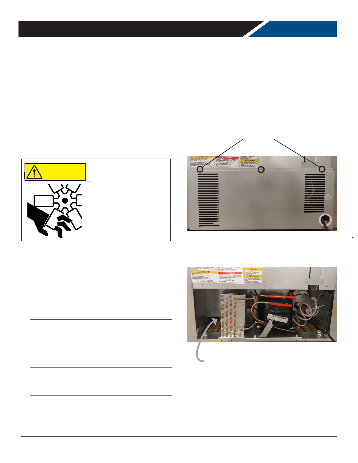
The condenser coil is located right behind the back grille
of the cabinet. It should be inspected once a month and
cleaned as required. Vacuum clean all surfaces of the
condenser. Make sure no ns are bent or damaged in the
process. If there are bent ns, carefully straighten them
so that air can ow through the coils. Failure to keep
the condenser coil clean will lead to poor performance,
excessive power consumption and compressor failure
and may result in loss of property. Failure to keep the
condenser coil clean may void the limited warranty.
Rotating fan blade can cause
CAUTION
personal injury.
Unplug unit from power supply
before beginning to clean
condenser
6. To reinstall the rear panel line up the bottom of the
panel to the bottom of the unit keeping the screw
holes lined up on the panel and on the unit.
7. Reinstall the Phillips head screw.
8.
Note: Air lters are not recommended as they restrict
the ow of cooling air.
Remove These
Screws
Remove This Panel
1. Unplug unit from power supply.
2. Remove the Phillips head screws at the top of the
panel.
3. Once the screws have been removed the you can lower
the panel.
Please note the electrical cord will still be connected to
the panel.
4. Examine condenser surface, if dusty, brush and
vacuum the dust and lint from the surface of the
coil. Brush up and down to avoid damaging the ns.
Use care to not disturb the wires connected to the
controller.
Note: If the coil is greasy, the coil will need to be
cleaned with coil cleaner and that should be left to an
experienced technician.
5. After the condenser is clean, return the grille panel to
the unit.
Condenser Surface
Rev. 10/20Beverage-Air18
Page 19
User Manual for UCF Freezers Beverage-Air
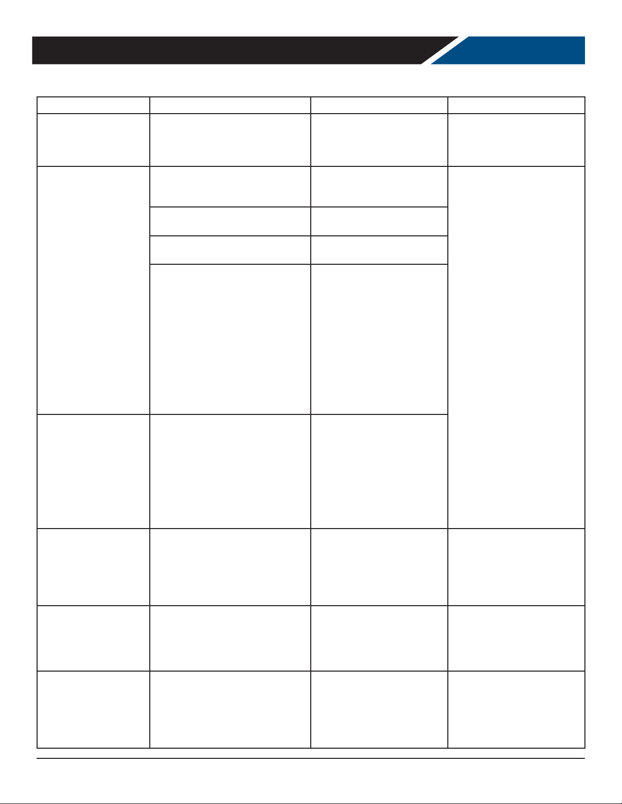
METHODS FOR CLEANING STAINLESS STEEL
Cleaning Needed Cleaning Agent Method of Application Aect on Finish
Satisfactory for use on all
nishes.
Provides barrier lm to
minimize prints.
Use in direction of polish lines
on No. 4 (polished) nish. May
scratch No.
2 (mill) and Nos. 7 and 8
(polished) nishes.
Smears and ngerprints
Stubborn Spots and
Stains, Baked-On
Splatter, and Other
Light Discolorations
Heat tint or
discoloration
Areal 20, Lac-O-Nu, Lumin Wash
O’Cedar Cream Polish, Stainless
Shine.
Allchem Concentrated Cleaner.
Samae, Twinkle or Cameo Copper
Cleaner
Grade FFF Italian pumice, whiting,
or talc.
Liquid NuSteel
Paste NuSteel or DuBois Temp.
Copper’s Stainless Steel Cleaner
Revere Stainless Cleaner
Household cleansers, such as
Old Dutch, Lighthouse, Sunbrite,
Wyandotte, Bab-O, Gold Dust,
Sapolio, Bon Ami, Ajax, or Comet
Grade F Italian Pumice, Steel
Bright, Lumin Cleaner, Zud,
Restore, Sta-Clean, or Highlite.
Penny-Brite or Copper-Brite.
Penny-Brite or Copper-Brite.
Past NuSteel, DuBois Temp,
or Tarnite. Revere Stainless Steel
Cleaner. Allen Polish, Steel Bright,
Tenacious Deposits,
Rusty Discolorations,
Industrial
Atmospheric Stains Wyandotte,
Bab-O or Zud.
Rub with cloth as directed
on the package.
Apply with damp sponge or
cloth.
Rub with damp cloth.
Rub with damp cloth.
Rub with dry cloth.
Use small amount of cleaner.
Rub with dry cloth using a
small amount of cleaner.
Apply with damp sponge or
cloth.
Rub with a damp cloth. May
contain chlorine bleaches.
Rinse
thoroughly after use.
Rub with a damp cloth.
Rub with a dry cloth using a
small amount of cleaner.
Rub with a dry cloth.
Rub with a dry cloth or stainless steel wool.
Apply with damp sponge or
cloth.
Rub with a damp cloth.
Burnt-On Foods and
Grease Fatty Acids,
Milkstone (where
swabbing or rubbing
is not practical)
Tenacious Deposits,
Rusty Discolorations,
Industrial
Atmospheric Stains
Hard Water Spots
and Scale
Rev. 10/20 Beverage-Air 19
Easy-O, De-Grease-It, 4 to 6%
hot solution of such agents as
trisodium phosphate or sodium
tripolyphosphate or 5 to 15% caustic
soda solution
Oakite No. 33, Dilac Texo 12, Texo NY,
Flash-Klenz, Caddy Cleaner,
Turco Scale 4368 or Permag 57.
Vinegar.
5% oxalic acid, 5% sulfamic acid, 5 to
10% phosphoric acid, or Dilac, Oakite
No. 33, Texo 12, Texo N.Y.
Apply generous coating. Allow
to stand for 10-15 minutes.
Rinse.
Repeated application may be
necessary.
Swab and soak with clean
cloth.
Let stand 15 minutes or more
according to directions on
package, then rinse and dry.
Swab or wipe with cloth. Rinse
with water and dry.
Swab or soak with cloth. Let
stand 10-15 minutes. Always
follow with neutralizer rinse,
and dry.
Excellent removal, satisfactory
for use on all nishes.
Satisfactory for use on all
nishes
Satisfactory for all nishes.
Satisfactory for all nishes.
Eective on tenacious deposits
or where scale
has built up.
Page 20
User Manual for UCF Freezers Beverage-Air
HELP
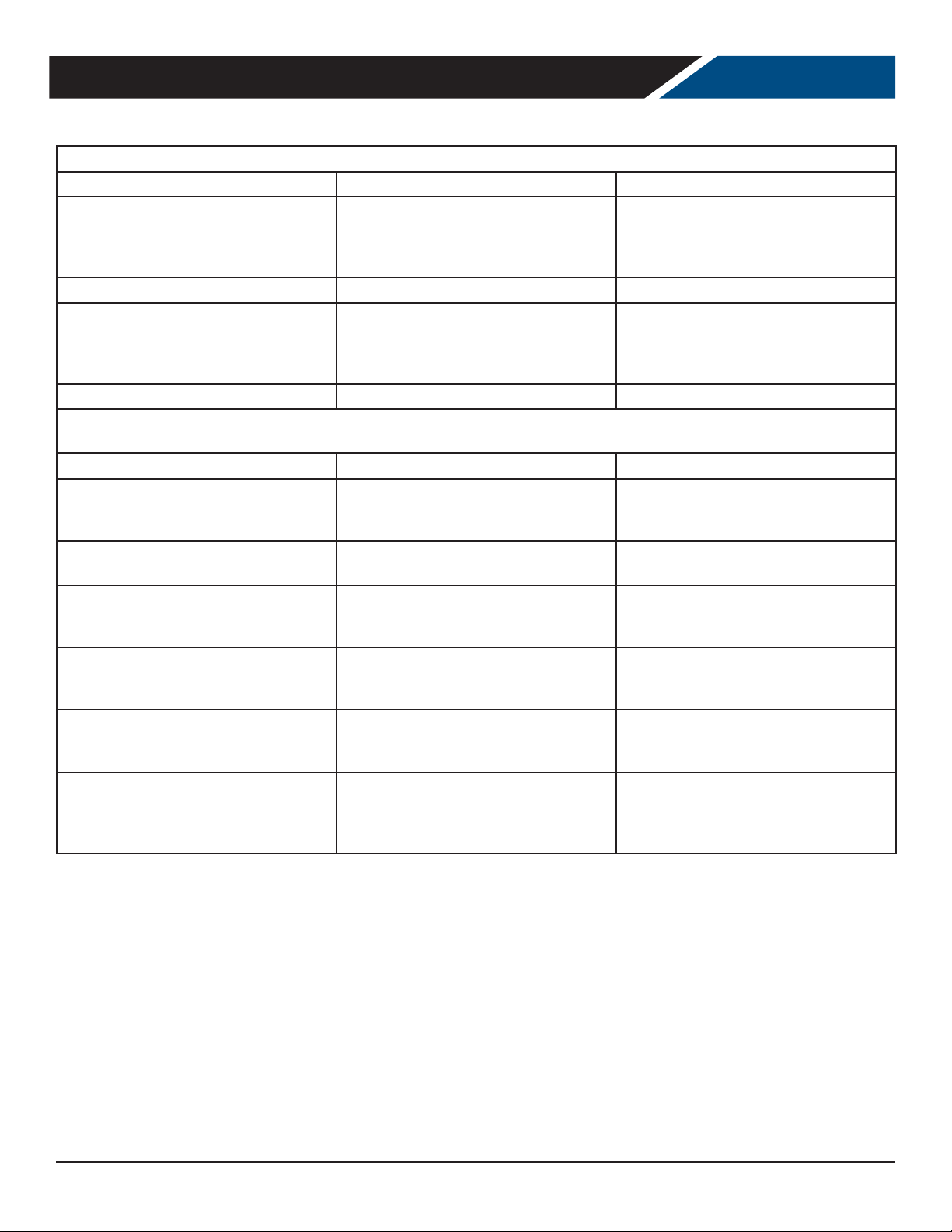
Trouble Diagnosis for the User
Malfunction Possible Cause Likely Solution
Unit not plugged in.
No cooling - unit is silent
Unit cools but seems to be on all the time Dirty condenser Clean condenser
Space temperature too high
Space temperature too low Temperature control Adjust or replace control
Trouble Diagnosis for the Technician
No cooling - compressor does not hum Temp control stuck in open position Replace temp control.
No cooling - compressor hums but does not
start
No cooling - compressor starts but shuts oCompressor start relay failure Compressor
No cooling - compressor cycles on and o Overheating weak overload
Unit cools, but is slow to pull cabinet
temperature down
Unit cools but turns on and o frequently
Fuse or circuit breaker tripped.
Power cord plug loose in outlet.
Dirty condenser
Evaporator iced over Unit in high
temperature environment
Low voltage to unit.
Compressor starting system failure
start capacitor failure
Evaporator fan not turning
No product in cabinet. Temperature control
defective Refrigeration issue
Connect to proper voltage circuit Replace
fuse or reset breaker.
Check outlet for loose connection, replace
as needed
Clean condenser Defrost evaporator
Reduce temperature of room
Check voltage, correct as needed. Check
start relay and start capacitor. See next
step.
Replace relay. Replace capacitor.
Clean condenser, check fan motor and
blade. Check refrigerant charge. Replace
overload.
Check fan(s), on multiple fan units one fan
may be turning slowly and will need to be
replaced.
Fill cabinet Replace control
Have system checked
Makes excessive noise
Tubing rattle Loose parts
Bent or broken fan blade Noisy fan motor
Check tubing for routing Check for loose
components Replace fan blade
Replace fan motor
Rev. 10/20Beverage-Air20
Page 21

User Manual for UCF Freezers Beverage-Air
FOR THE SERVICE TECH - R290
Refrigeration service should only be attempted by a trained trade professional certied to work on R290 systems.
Here are some critical service items.
This list does not qualify anyone to service the unit. It is a
reminder and checklist for the service tech. Keep these in
mind for R290 service:
• Wire nuts are NOT to be used when changing an
electrical part.
• The switches in this product are sealed, only exact
replacements may be used.
• The process tubes are to be used for service access.
• Cut out (with tubing cutter) refrigeration components
that are to be replaced. Do NOT un-braze.
• Because R290 can be vented into the air during
service, the venting MUST be in an area free from
ame or spark. It must also be in a well ventilated
area, with a nearby open window or door.
• A sign noting service of a system containing propane
must be attached to the unit during refrigeration
service.
Other Information:
Evacuation: It is critical that a refrigeration system be
leak free and internally dry. A thorough evacuation with
a good vacuum pump with a micron gauge attached is the
only way to ensure that the system is dry and ready for a
charge of refrigerant.
Charging: The system is critically charged and the proper
type and amount MUST be weighed in.
Overcharge symptoms: Unit will cool properly but
the suction line temperature will be unusually cold.
Compressor run time will be longer than normal.
Undercharge symptoms: Long run time, poor cooling and
a hot compressor dome are the main symptoms of an
undercharge.
• A combustible gas leak detector must be used to
inform anyone in the area when propane is present in
the air.
Rev. 10/20 Beverage-Air 21
Page 22
User Manual for UCF Freezers Beverage-Air
LIGHT (NOT ALL MODELS)
TEMP SENSOR AIR
TEMP SENSOR COIL
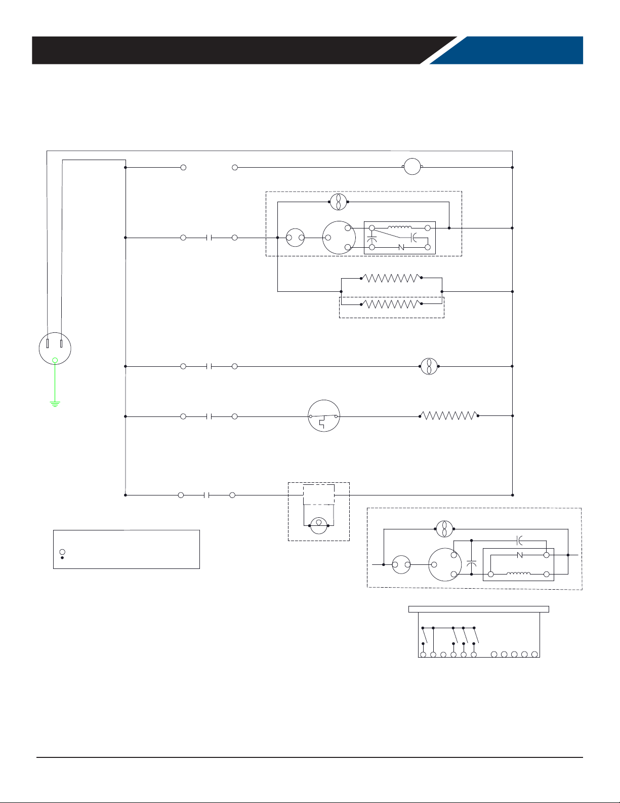
FOR THE SERVICE TECH - WIRING DIAGRAM
WHITE
BLACK
BLACK
BLACK
2
*SEE CONTROLLER DETAIL
2
*SEE CONTROLLER DETAIL
2
*SEE CONTROLLER DETAIL
2
*SEE CONTROLLER DETAIL
WHITE
START RELAY
R.C.
CNTRL
S.C.
10
1
EVAP FAN
DEFROST HEATER
WHITE
3
COMPRESSOR DETAIL
CONDENSER FAN
4
1
5
6
OL
HEATER SAFETY
THERMAL SWITCH
C
COMP
R
S
2
FACE HEATER
DOOR HEATER
GLASS DOOR MODELS ONLY
RC - RUN CAPACITOR
SC - START CAPACITOR
OL - OVERLOAD
1
- DANFOSS CONTROLLER TERMINAL
- CONNECTION POINT
- CONTROL RELAY
1CR
LEGEND
2
*SEE CONTROLLER DETAIL
4
POWER
SUPPLY
LAMP
L.E.D. LAMP
COMPRESSOR DETAIL FOR SOME MODELS
CONDENSER FAN
S.C.
*NOT ALL MODELS*
OL
1
COMPRESSOR
R
C
COMP
S
DANFOSS CONTROLLER DETAIL
5
3 4
2
FAN
SUPPLY-L
SUPPLY-N
R.C.
6
DEFROST
2
S1
START RELAY
S3 S4
S2
1
5
DI
Rev. 10/20Beverage-Air22
Page 23

User Manual for UCF Freezers Beverage-Air
LIMITED WARRANTY
WARRANTY (Warranty valid in USA and Canada)
THREE (3) YEAR PARTS AND LABOR WARRANTY:
Beverage-Air Corporation warrants to the original
purchaser of Beverage-Air branded equipment, including
all parts thereof, that such equipment is free from defects
in material and workmanship, under normal use, proper
maintenance, and service as indicated by Beverage-Air
installation and operation instructions, for a period of three
(3) years from the date of installation, or thirty-nine (39)
Months from the date of shipment from the manufacturer,
whichever is earlier.
ADDITIONAL FOUR (4) YEAR COMPRESSOR PART
WARRANTY*: In addition to the warranty set forth above,
Beverage-Air warrants the hermetically/semi-hermetically
sealed compressor (part only) for an additional FOUR (4)
years beyond the rst three (3) years warranty period;
not to exceed eighty-seven (87) months from the date of
shipment from Beverage-Air, provided upon receipt of the
compressor, manufacturer examination shows the sealed
compressor to be defective. This extended warranty does
not cover freight for the replacement compressor or freight
for the return of the failed compressor.
* Units shipped after 03/01/2020. Previous warranty
applies to units shipped prior.
EXCEPTIONS:
CT96 Models carry a one (1) year parts and labor warranty,
limited to fteen (15) months from date of shipment
from Beverage-Air. These are excluded from additional
compressor warranty.
SR/SF (Slate) models carry a two (2) year parts and labor
warranty, limited to twenty-seven (27) months from date of
shipment from the Beverage-Air.
Blast Chillers carry a three (3) year parts and labor
warranty; additional two (2) years compressor part only.
Units installed in Residential applications will be not
covered under this warranty. Units are intended for
Commercial use only.
BEVERAGE-AIR
Also, this extended compressor-part only warranty does
NOT apply to any electrical controls, condenser, evaporator,
fan motors, overload switch, starting relay, capacitors,
temperature control, lter/drier, accumulator, refrigeration
tubing, wiring harness, labor charges, or supplies which are
covered by the warranty above.
Normal wear type parts, such as light bulbs/lamps and
gaskets are not covered by this warranty. For the purpose
of this warranty, the original purchaser shall be deemed to
mean the individual or company for who the product was
originally installed.
Our obligation under this warranty shall be limited to
repairing or replacing, including labor, any part of such
product, which proves thus defective. Beverage-Air
reserves the right to examine any product claimed to be
defective.
The labor warranty shall be for self-contained units
only and for standard straight time, which is dened as
normal service rate time, for service performed during
normal working hours. Any service requested outside of
a servicer's normal working hours will be covered under
this warranty at the normal rate and any additional
overtime rate will be at the responsibility of the equipment
purchaser.
Any part or accessory determined to be defective in the
product should be returned to the company within thirty
(30) days under the terms of this warranty and must be
accompanied by a record of the cabinet model, serial
number, and identied with a return material authorization
number (RMA#) issued by the manufacturer.
Special installation/applications, including remote locations,
are limited in coverage by this warranty. Any installation
that requires extra work, and/or travel, to gain access to the
unit for service is the sole responsibility of the equipment
purchaser.
Improper operation resulting from factors, including but not
limited to, improper or negligent cleaning and maintenance,
low voltage conditions, inadequate wiring, outdoor use
(unless otherwise specied) and accidental damage are no
manufacturing defects and are strictly the responsibility of
the purchaser.
Rev. 10/20 Beverage-Air 23
Page 24

User Manual for UCF Freezers Beverage-Air
LIMITED WARRANTY (CONTINUED)
With the exception of Blast Chillers product is designed for
maintaining temperature and not bringing food to a desired
temperature therefore cannot be held responsible for this
function under warranty.
Units must be in a conditioned environment or warranty
will be void.
Condensing coils must be cleaned at regular intervals.
Failure to do so can cause compressor malfunction and will
void warranty. Although cleaning requirements vary in
accordance with operation of various products, BeverageAir recommends a minimum monthly cleaning.
NO CLAIMS CAN BE MADE AGAINST THIS WARRANTY
FOR SPOILAGE OF FOOD. PRODUCTS, LOSS OF SALES OR
CONSEQUENTIAL DAMAGES.
THE FOREGOING WARRANTIES ARE EXPRESSLY GIVEN
IN LIEU OF ALL OTHER WARRANTIES, EXPRESS, IMPLIED,
OR STATUTORY, INCLUDING THE IMPLIED WARRANTIES
OF MERCHANTABILITY AND FITNESS FOR A PARTICULAR
PURPOSE, WHICH ARE HERBY DISCLAIMED, ALL OTHER
OBLIGATIONS OR LIABILITIES ON OUR PART, AND WE
NEITHER ASSUME, NOR AUTHORIZE ANY OTHER PERSON
TO ASSUME FOR US, ANY OBLIGATION OR LIABILITY IN
CONNECTION WITH THE SALE OF SAID REFRIGERATION
UNITS OR ANY PARTS THERE OF.
LIMITATION OF LIABILITY:
Beverage-Air Corporation or their aliates shall not be
liable for any indirect, incidental, special or consequential
damages, or losses of a commercial nature arising out of
malfunction equipment or its parts components thereof, as
a result of defects in material or workmanship.
THE ORIGINAL OWNER'S SOLE AND EXCLUSIVE REMEDY
AND BEVERAGE-AIR'S SOLE AND EXCLUSIVE LIABILITY
SHALL BE LIMITED TO THE REPAIR OR REPLACEMENT OF
PARTS OR COMPONENTS CONTAINED IN THE EQUIPMENT
IDENTIFIED ABOVE WHICH UNDER NORMAL USE AND
SERVICE MALFUNCTION AS A RESULT OF DEFECTS
IN MATERIAL OR WORKMANSHIP, SUBJECT TO THE
APPLICABLE PROVISIONS AND LIMITATIONS STATED
ABOVE.
This warranty shall not be assignable and shall be honored
only in so far as the original purchaser. This warranty
does not apply outside the limits of the United States of
America and Canada, nor does it apply to any part that has
been subject to misuse, neglect alteration, accident, or to
any damage caused by transportation, ood, re, acts of
terrorism, or acts of God.
Rev. 10/20Beverage-Air24
Page 25
User Manual for UCF Freezers Beverage-Air
Warranty Registration
Register your product online at beverage-air.com/parts-service or ll out and mail the form below.
Cabinet Model Number: _____________________________________________ Date Of Installation: _________________
Cabinet Serial Number: _____________________________________________
Location Of Product
Business Name: ____________________________________________________
Business Street: ____________________________________________________
Business City: ____________________________________ State: _________ Postal Code:___________
Mail to: Beverage-Air, 3779 Champion Blvd, Winston-Salem, NC 27105
Rev. 10/20
 Loading...