

Page 1
SERVICE &
INSTALLATION
MANUAL
1/03
51-1450-01
CARRIER COMMERCIAL REFRIGERATION, INC.
LOW TEMPERATURE
VERTICAL FREEZERS
Providing BEVERAGE-AIR • FRIGIDAIRE • KELVINATOR • UNIVERSAL NOLIN Products/Services
Page 2

If additional information is necessary, call the factory.
Our toll free number is 1-800-684-1199.Technical
assistance engineers are willing to assist you in any way
possible. Office hours are from 8:00a.m. to 5:30 p.m.,
Eastern Standard Time.
Important information is contained in this manual which should
be retained in a convenient location for future reference.
ALL DATA AND INFORMATION IN THIS MANUAL IS SUBJECT TO CHANGE WITHOUT NOTICE.
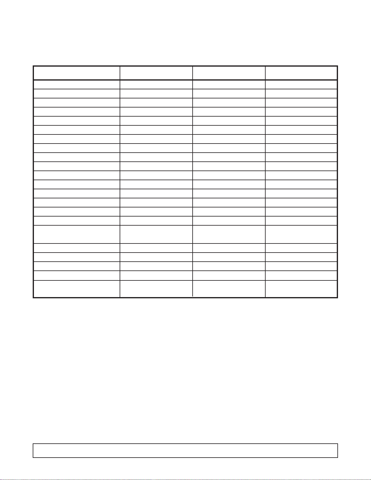
MODEL DESIGNATION INFORMATION
PART NO. MODELS STYLE CONDENSER SPECIAL USE
52-1923-02 BT30CW-EXPR SOLID ONE DOOR TOP MOUNT EXPLOSION PROOF
52-1958-01 BT30CWFMS-2 SOLID ONE DOOR TOP MOUNT FLAMMABLE MAT'L STORAGE
52-1993-06 BT30FS-4 SOLID ONE DOOR TOP MOUNT SCIENTIFIC GENERAL PURPOSE
52-1993-12 BT50FS-4 SOLID TWO DOOR TOP MOUNT SCIENTIFIC GENERAL PURPOSE
52-1993-18 BT80FS-4 SOLID THREE DOOR TOP MOUNT SCIENTIFIC GENERAL PURPOSE
52-1993-21 BTL30FS-4 SOLID ONE DOOR TOP MOUNT SCIENTIFIC LOW TEMPERATURE
52-1993-22 BTQ50FSHD-4 SOLID QUAD DOOR TOP MOUNT SCIENTIFIC LOW TEMPERATURE
52-1993-25 ST30FSBB-4 SOLID ONE DOOR TOP MOUNT BLOOD STORAGE
52-1993-28 STL30FSBB-4 SOLID ONE DOOR TOP MOUNT BLOOD STORAGE LOW TEMP
52-1991-07 T30HSP-4 SOLID ONE DOOR TOP MOUNT HARDENING
52-1991-36 T30LGP-5 GLASS ONE DOOR TOP MOUNT
52-2026-10 T30LGPE-5 GLASS ONE DOOR TOP MOUNT EXPORT (220V 50HZ)
52-1997-26 T30LGPRBR-5 GLASS ONE DOOR REMOTE TOP
52-1991-50 T30LSP-5 SOLID ONE DOOR TOP MOUNT
52-1991-69 T30LSPHD-5 SOLID ONE DOOR TOP MOUNT HEAVY DUTY
52-1991-14 T50HSQHP-4 SOLID QUAD DOOR TOP MOUNT HARDENING
52-1991-15 T50HSQL-4 SOLID QUAD DOOR TOP MOUNT HARDENING
52-1991-38 T50LGP-5 GLASS TWO DOOR TOP MOUNT
52-2026-11 T50LGPE-5 GLASS TWO DOOR TOP MOUNT EXPORT (220V 50HZ)
52-1991-41 T50LGPHD-5 GLASS TWO DOOR TOP MOUNT HEAVY DUTY
52-1997-24 T50LGPR-5 GLASS TWO DOOR REMOTE TOP
52-1991-54 T50LSP-5 SOLID TWO DOOR TOP MOUNT
52-1997-33 T50LSPR-5 SOLID TWO DOOR REMOTE TOP
52-1991-44 T80LGP-5 GLASS THREE DOOR TOP MOUNT
52-2026-12 T80LGPE-5 GLASS THREE DOOR TOP MOUNT EXPORT (220V 50HZ)
52-1997-25 T80LGPR-5 GLASS THREE DOOR REMOTE TOP
52-1991-60 T80LSP-5 SOLID THREE DOOR TOP MOUNT
52-2026-07 ULG30BF-5 GLASS ONE DOOR BOTTOM MOUNT EXPORT (220V 50HZ)
52-1992-19 ULG30BS-5 GLASS ONE DOOR BOTTOM MOUNT
52-1992-20 ULG50BC-5 GLASS TWO DOOR BOTTOM MOUNT
52-2026-08 ULG50BF-5 GLASS TWO DOOR BOTTOM MOUNT EXPORT (220V 50HZ)
52-1997-22 ULG50RD-5 GLASS TWO DOOR REMOTE BTM
52-1992-23 ULG80BC-5 GLASS THREE DOOR BOTTOM MOUNT
52-2026-09 ULG80BF-5 GLASS THREE DOOR BOTTOM MOUNT EXPORT (220V 50HZ)
52-1997-23 ULG80RD-5 GLASS THREE DOOR REMOTE BTM
52-1997-32 ULS30US-5 SOLID ONE DOOR REMOTE TOP
This manual pertains to units produced beginning with serial number
Page 3

TABLE OF CONTENTS 1
TABLE OF CONTENTS-LOW TEMP. VERTICAL
MODEL CODES EXAMPLES..................................................2
HANDLING & INSTALLATION ..............................................5
TOP MOUNT, GLASS PULL DOOR (1-,2-,& 3-DR MODELS)
Dimensional Drawings........................................................10
Freezer Specifications ..........................................................7
BOTTOM MOUNT, GLASS PULL DOOR (1-, 2-, 3-DR MODELS)
Dimensional Drawings........................................................12
Freezer Specifications ........................................................13
TOP MOUNT, SOLID PULL DOOR (1 & 2-DR MODELS)
Dimensional Drawings ......................................................14
Freezer Specifications ........................................................15
TOP MOUNT, SOLID PULL DOOR
HARDENING & FLASH FREEZERS
Freezer Specifications ........................................................16
ELECTRICAL & REFRIGERATION INFORMATION
........................................................................17
ELECTRICAL & REFRIGERATION INFORMATION
BT30CWFMS
........................................................................79
ELECTRICAL & REFRIGERATION INFORMATION
BT30CWEXPR
......................................................................85
WIRING & PIPING INFORMATION
REMOTE CABINET
..........................................................103
MAINTENANCE & REPAIR ..........................................47
PA RTS LIST....................................................................117
Page 4

2 INTRODUCTION
These Freezers have been designed to maintain a low
temperature environment. These multi-purpose freezers
are available in one-, two-, and three-door solid or glass
door models.
Except for routine cleaning, these low temperature cabinets
will require little maintenance. In the unusual event that
repair should be necessary, this manual presents information
that is helpful in maintaining, diagnosing, and repairing
these cabinets.
Low Temperature Vertical Freezers
Introduction
Page 5

MODEL CODES - KELVINATOR & KELVINATOR SCIENTIFIC 3
MODEL CODES
Kelvinator Model Example: T30LGPR-5
T30LGP R-5
T = Top Mount
B = Bottom Mount
FS = Food Service
30, 50, 80 - Cubic Feet
L = Low Temp
M - Medium Temp
H = Hardening Cabinet
G= Glass Door
S = Solid Door
P = Pull Door
S = Sliding Door
Q = Quadrant Pull Door
R = Remote
E = Export
ET = Export Transformer
Customer Variations:
BR = Baskin Robbins
DQ = Dairy Queen
DQL = Dairy Queen Light Duty
4 = Revision Level
Kelvinator Scientific Model Example: ESTL50RSFMS-4
ESTL50RSFMS -4
E = Export
ET = Export (Transformer)
S = Scientific
B = Base Scientific
T = Top Mount
B = Bottom Mount
C = Chest
L = Hardening Cabinet
30, 50, 80 =
Cubic Feet
F = Freezer
R = Refrigerator
G = Glass Door
S = Solid Door
I = Incubator (Solid Door)
FMS = Flammable Material Storage
CH = Chromatography
BB = Blood Bank
EXPR = Explosion Proof
R = Recorder on Incubator
Customer Variations:
XXX
4 = Revision Level
Page 6

4 MODEL CODES – UN
MODEL CODES
Universal Nolin Model Example: UMG50BS-4
UMG50B S-4
U = Upright
S = Scientific (upright)
L = Low Temp.
M = Med Temp.
H = Heated Glass (medium temp.)
G = Glass
S = Solid
O = Open
T = Sliding Glass Door (track)
30, 50, 80 =
Cubic Feet
R = Remote on Bottom Mounted Upright
U - Remote on Top Mounted Upright
T = Top Mounted Compressor
B = Bottom Mounted Compressor
S = Single Facing (sliders)
D = Double Facing
S = 115V / 60 Hz.
D = 208/230V / 60 Hz. / 1 Ph.
P = 208V / 60 Hz. / 3 Ph.
T = Transformer
F = 220V / 50 Hz.
4 = Revision Level
Page 7

SECTION I – HANDLING & INSTALLATION
HANDLING & INSTALLATION 5
FREIGHT DAMAGES & SHORTAGES
The cabinet was inspected and
packaged at the factory, and should
arrive in excellent condition. The transportation
company or other par ties involved in the shipment are
responsible for loss and/or damage. Always make an
inspection before and after uncrating. Inspect the
crated unit(s) before locating (preferably at the point of
unloading by the transportation company).
INSPECTING FOR DAMAGES
Always use care when removing shipping
tape, blocks, pads, hardware or other
material until you are satisfied that the unit is
completely operational.Contact the factory if technical
assistance is required.
Check the cartons or containers.If these are damaged
in any way, open them and inspect the contents in the
driver’s presence. If damage is detected:
1. Have the driver note the nature and extent of the
damage on the freight bill.
2. Notify the transportation company at once to request
an inspection. Carrier claim policies usually require
inspections to be made within 15 days of delivery.
3. If damage is noticed, file a claim with the
transportation company.
FILING A CLAIM
File a claim for loss at once with the transportation
company for:
A. A cash adjustment; B. Repairs; or C. Replacement.
When filing your claim, retain all packaging materials
and receipts.
HANDLING THE CABINET
The refrigeration system of the cabinet is
designed to operate with the cabinet located
on a level surface. Do not tilt the cabinet more than
10° to any side. If the cabinet must be tilted on an
angle for handling or moving purposes, allow it to sit in
an upright position 30 minutes prior to starting.
CHOOSING A LOCATION
This model cabinet should be situated to allow proper air
circulation. These cabinets require a 2" minimum
clearance behind for proper air circulation.
The cabinet must be installed on sturdy, solid, level floor.
The cabinet must be located so it can be plugged into a
properly grounded three-prong electrical outlet of 115
volt, 60 hz.The electrical outlet should not be controlled
by a wall switch which might be turned off accidentally.
UNCRATING THE CABINET
The cabinet should be moved as close as possible to the
operating location before removing crate base. Be sure
to follow the steps in the “INSPECTING FOR
DAMAGES”instructions.
INSTALLING THE CABINET
(Models with Top Mounted Compressor)
Whenever possible leave the crate base on the cabinet
until it is moved close to the final position. When it is
necessary to move the cabinet through a doorway, it
may be necessary to remove the crate base.
Wood runners are provided on the underside of the
cabinet for ease in sliding.These runners should be left
attached to the cabinet when the crate base is removed
and should remain attached until after the legs are
installed.The cabinet can then be pushed around more
easily without scratching the floor. The runners also
prevent damage to the electrical receptacle and
condensate pan hardware on the cabinet bottom.
After the cabinet has been moved to the approximate
final location, remove the package containing the legs
from the cabinet interior. Tape the doors to prevent
accidental opening when handling. Raise the sides of
the cabinet high enough to mount the legs at the
locations provided on the bottom of the cabinet.
IMPORTANT:
AFTER
REMOVAL OF
WOOD RUNNER,
REPLACE BOLT
“A” INTO LEG
MOUNTING
BRACKETS.THIS
IS EXTREMELY
IMPORTANT TO
THE SECURE
ATTACHMENT
OF THE
CABINET LEG.
THERE MUST
BE FOUR (4)
BOLTS
SECURING
EACH LEG.
Level the cabinet by means of the leg adjustments.
Cabinet doors are self-closing, and the cabinet must be
level to operate properly.
NOTE:
IMPORTANT:
NOTE:
Page 8

6 HANDLING & INSTALLATION
CONDENSATE PAN
INSTALLATION INSTRUCTIONS
MAKE SURE THE CABINET IS DISCONNECTED
FROM ITS POWER SOURCE
1. Remove and discard protective cover over electrical
receptacle on bottom of cabinet
2. Bend down front part of housing. (See above.)
3. Insert condensate evaporator pan assembly into the slide
supports on the underside of the cabinet by pushing
toward back of cabinet until it stops.
4. Plug supply cord into receptacle in underside of cabinet.
5. Bend up front part of housing. Line up slot with rivnut in
cabinet bottom and insert thumbscrew through slot onto
rivnut in cabinet bottom. Insert thumb screw through slot
onto rivnut and tighten.
6. The assembly will now operate when power is supplied to
the cabinet.
7. Inspect rear of cabinet to ensure that the drain line from
the evaporator is properly positioned over the
condensate pan.
On top mount models, allow a minimum of twelve (12)
inches between the top of the cabinet and ceiling and two (2)
inches from the back of the cabinet to the wall, for proper air
circulation through the condensing unit.
(Models with Bottom Mounted Compressor)
Remove the crate base mounting clips located behind the
front grill.Slide the cabinet forward on the crate base to clear
the rear mounting clips.
After removing the crate base, move the cabinet into
location. Make sure the cabinet is level to ensure operation
of the “self-closing” doors.
Allow a minimum of two (2) inches between the back of the
cabinet and the wall for proper air circulation through the
condensing unit.
CABINET STARTUP
Once the cabinet has been located in its permanent location
and the proper power and grounding have been provided,
the following items must be checked or completed:
1. Cut and remove the compressor hold-down band (if
applicable) so the compressor “floats” freely.
2. Check for traces of oil on the compressor pan which could
mean a broken or leaking refrigeration line.
2. UNDER NO CIRCUMSTANCE SHOULD THE
COMPRESSOR BE STARTED WHEN OIL IS PRESENT
UNTIL INSPECTED BY A SERVICE TECHNICIAN.
3. INSPECT THE FACTORY WIRING FOR TERMINALS
THAT MIGHT HAVE VIBRATED LOOSE IN SHIPPING.
TIGHTEN ALL SCREW-TYPE TERMINALS.
4. Check the refrigeration lines to see that they are “free”
and no damage was done during shipping.
5. Check fan blade(s) for “free” operation.
6. Turn on the main power switch. Once the compressor
starts, the voltage should be checked at the compressor
terminals to determine if there is proper voltage to the
compressor.The voltage should not e xceed 10% abo v e or
below the rated compressor voltage.
EXAMPLE: If the voltage reads 115 volts with no load and it
drops below 103 volts when the compressor starts, it
may indicate that the supply wiring is too small or that
the wire run is too long.
7. Make sure that the drain line has not been dislodged or
broken during shipping and that the drain trap
terminates properly in the condensate pan or floor drain.
(See Condensate Pan on top mounted compressor.)
8. Listen for any unusual noise such as lines vibrating, etc.
Correct problem by tightening screws, slightly bending
tubing, etc.
9. Check proper tension on doors. (See Door Torque
Adjustment.)
10. NOTE: Allow cabinet to pull down and cycle prior to
loading with product.
11. a 2" clearance must be maintained between the back
wall and product shelving to allow for proper air
movement within the cabinet.
SYSTEM CONTROL/OPERATION
ELECTRO-MECHANICAL
Thermostat Settings
The freezer is shipped from the factory with a thermostat
setting of approximately the mid-point of the operating
range. Final thermostat setting must be made in the field.
Allow the cabinet to operate until the compressor cycles on
the thermostat. The normal operating temperature range for
the refrigerator is:
0°F to -20°F (-17°C to -26°C) for freezer models;
0°F to -40°F (-17°C to -40°C) for low temp. freezer models;
and 5°F to 122°F (-15°C to -50°C) for incubator models
The thermostat is easily adjusted with a standard
screwdriver.
NOTE: DO NOT OPERATE THE CABINET WITH
THERMOSTAT SETTINGS BELOW:
-23°F (-30°C) ON FREEZERS;
-40°F (-40°C) ON LOW TEMP. FREEZERS;
The cabinet thermostat is located on the electrical box (top
mount models) top left hand side of cabinet. It can be
accessed without re4moving the front top panel with the use
of a stepladder, and a screw driver.
Cabinet Operation
(Freezer & Low Temp. Freezer)
There are two thermodiscs located on the evaporator coil.
The purpose of one is to keep the evaporator fan motors
and anti-condensate heater off after defrost cycles until the
coil reaches 32°F (O°C). This prevents moisture from being
pulled down into the product area and provides faster pulldown.The purpose of the other control is to de-energize the
defrost heater and to energize the trip solenoid in the time
clock to terminate the defrost cycle when the fin coil reaches
62°F (17°C).
FIGURE 2
Page 9

When the refrigeration system first starts up, the room
temperature and the coil temperature are above 62°F(17°C).
The fan delay thermostat is open and the fans and anticondensate heaters remain off.The fan motors will come on
when the evaporator temperature is pulled down to
approximately 32°F (0°). This fan delay control cannot be
adjusted. If a single fan motor fails to start when the
thermostat is below 32°F (0°C), it may be an indication of a
defective fan motor. If all fan motors fail to start, it is an
indication of a defective fan delay control.
NOTE: ON SOME MODELS, THE EVAPORATOR FANS
TURN OFF WHEN THE DOORS ARE OPENED.
SYSTEM CONTROL/OPERATION
ELECTRONIC (PULSE)
Note: The “Pulse” information that follows pertains to set-up
and basic operation. For more comprehensive operation,
repair, and maintenance information refer to the Pulse
service manual part number 51-2484-00.
Display Settings
the freezer is shipped from the factory with a thermostat
setting of approximately the midpoint of the operating range.
Final thermostat setting must be made in the field.
The normal operating temperature ranges are:
0°F to -20°F (-17°C to -26°C) for freezer models;
0°F to -40°F (-17°C to -40°C) for low temp. freezer models;
and 5°F to 122°F (-15°C to -50°C) for incubator models
NOTE: DO NOT OPERATE THE CABINET WITH
THERMOSTAT SETTINGS BELOW:
-23°F (-30°C) ON FREEZERS;
-40°F (-40°C) ON LOW TEMP. FREEZERS;
Cabinet Temperature
& Defrost Management
These functions are controlled by a computerized control
board located in the electrical box behind the front grill.The
control board utilizes 3 inputs, a display board, and two
temperature sensors.The display allows the user to monitor
the change the cabinet temperature (located with-in the door
frame).
Cabinet Operation
When supply power is hooked up to cabinet and power
switch is turned on. The control board has a built-in 3 minute
delay on start up.The cabinet temperature display will read
the current cavity temperature. The cavity temperature set
point can now be set or checked by depressing lower right
button on the display board.The upper right button will raise
the cabinet temperature set point. this can be done with an
ordinary paper clip.the lower left button is a service interface
and only a qualified service technician should activate this
program. the evaporator fans should start up as the coil
reaches 28°F the cabinet temperature will continue to drop
until the cavity temperature set point is reached.
NOTE: Control board only breaks on side of supply voltage
to the compressor and defrost circuit.
Notable points
1. The system utilizes a 3 minute off cycle timer to prevent
short cycles.
2.When the system initiates a defrost, the setpoint will flash
on and off until the defrost is terminated and the cavity
reaches the setpoint. At this time the cavity temperature will
be displayed as normal.
Display Functions
NOTE: Use a paper clip to access the function keys.
1. Pressing the top right button on the display unit will raise
the set point one degree. Holding the button down will
scroll the adjustment.
2. Pressing the bottom right button on the display unit will
lower the set point one degree. Holding the button down
will scroll the adjustment. After an adjustment is made the
cavity temperature will automatically return to the display
after a brief moment.
3.When the system enters a defrost state, the set point will
flash on and off repeatedly on the display and continue to
flash until the defrost state is terminated and the cavity
temperature returns to the set point. At this time the cavity
temperature will be displayed as normal.
4.Touching an y ke y on the display will ac knowledge and turn
off the local audible alarm as well as the optional remote
alarm.
IMPORTANT: When the freezer is plugged in or anytime
power is disrupted and then restored, the system will
pull down to the set point, begin the cycle, and then
initiate a defrost in 3.2 hours from initial start-up.This is
normal and is part of the initialization mode for the
microcontroller to collect data from the system.
The Service Interface and the Service Menu
The service menu offers the service technician direct control
of the components of the system.This allows the technician
to force the system into a defrost state or the refrigeration
state. This feature also allows the technician to toggle the
state in order to analyze separate components of the system
(e.g., start kit, compressor, heaters, etc.).
1. To access the service menu, press and hold lower left
button on the display with a paper clip for 2 seconds.The
system will enter the service menu and c0 will alternately
flash with evaporator temperature. This is the top of the
service menu. to exit the service menu, press the service
key again at any time.
2.The service menu offers five functions: Refrigeration
state, Defrost state, code revision level indication, the
option to blank the display (code version 1.6 and later),
Service
Interface
Indicates T emp .
below 0°F
Setpoint up
Setpoint down
HANDLING & INSTALLATION 7
Page 10

Celsius or Fahrenheit operation (code version 1.6 and
later), and Error code history (code 3.1 and later). While
in the service menu, the down key serves to scroll the
men and the up key serves as a toggle 6to activate and
deactivate the function state.
A.Hold lower left button for 2 seconds to enter service
menu.
1. Upper right key toggles current menu item “on”
(indicated by a “1” in the right hand digit of the
display and an “off” (indicated by a “0” in the right
hand digit of display).
2. Lower right key scrolls down through the menu.
a) 1st item: Refrigeration state (on or off)/ ev aporated
temp.This state is denoted by a “C0”or a
“C1” on the display alternately flashing
with the evaporator temperature.
b) 2nd Item: Defrost state (on or off) This state is
denoted by a “d0” or a “d1” on the
display.
c) 3rd Item: Code version (passive state, no action)
d) 4th Item: Display state (on or off) This state is
denoted by a “S0” or a “S1”. Note: Does
not turn off display o error codes.
e) 5th Item: Temperature state (Fahrenheit or
Celsius) This state is denoted by a “F” or
a “C”.
f) 6th Item:Error Code histor y (view and clean) This
state allows the ability to view and clean
the last three error codes encountered by
the unit. If no errors occurred since last
cleaned, this item is skipped and display
returns to 1st item.
33.Lower left key to exit service menu.
Notes: a. When an attempt is made to scroll the menu
while a function state is active, the active
function state will automatically deactivate. This
is to prevent the service technician from
simultaneously activating the Refrigeration state
and the Defrost state. Only one function may be
active at any give time.
b. If no operation is performed within 45 minutes
while in the service menu, the system will
automatically exit the service menu and return to
normal refrigeration.
c.If the Defrost state is activated and left
unattended, the service menu will terminate the
defrost as normal on evaporator temperature;
otherwise, the defrost will terminate in 45
minutes.Upon defrost termination the system will
automatically exit the service menu.
d. When the system exits the service menu, the
compressor will not start for 3 minutes.
e.The off cycle timer is not incorporated in the
service menu so the service technician has
direct control of components.
SCIENTIFIC CONTROL AND
ANNUNCIATOR PANELS
Cabinets for Scientific use may be equipped with a variety
of optional control, alarm, and recorder devices. Each
cabinet is shipped with the appropriate operators manual
for the device installed on the cabinet. These operator
manuals pertain to the set-up and basic operation of the
control panel devices. For more comprehensive operation,
repair, and maintenance information refer to the control
panel service manual part number 51-0170-01.
8 HANDLING & INSTALLATION
Page 11

HANDLING & INSTALLATION 9
QUAD DOOR HARDENING FREEZER
These cabinets were developed for low temperature storage
(-30°F, -34°C + -40°F, -40°C). Defrost timer to be set 8 A.M.,
4 P.M. and 12 P.M. Failsafe to be set at 30 minutes. Defrost
will terminate by time only. The temperature control is
located on the side of the electrical box. It can be adjusted
without removing the upper control panel.
Ways to Minimize Frost & Ice
Buildup Inside Hardening Freezers
Moisture-laden air migrates into the freezer during door
opening and under normal operation, will be absorbed or
removed by the refrigeration system and the defrost cycle.
The lover the temperature is in the freezer, the more rapidly
frost and ice will accumulate. Opening doors frequently will
also increase frost and ice buildup.
There are several things that you can do to reduce the
accumulation of lice/frost on the interior parts of the cabinet
and product. If this icing condition exists, the following items
should be checked and corrected as required.
1. Minimize door openings by using the hardening freezer to
harden the product, then move to a storage or display
freezer that is less critical in temperature.
2.Keep the length of time door is open to a minimum.
3. Avoid opening all doors at once. Open only one of the
outer doors plus only one of the inner doors (top or bottom)
at one time on the hardening freezer.
4. Check the door gaskets for possible air leaks. Look for
frost patches around the door openings of both the inner and
outer doors. Make sure that gasket seals all around door
opening; any leak will allow moist outside air to enter the
cabinet.
5. Make sure the inner door latches work properly.
6.These freezers are designed to operate in a range of -15°
to -40°F. Keep freezer thermostat set as high as possible to
minimize frost buildup.
7. Look for moisture draining from the drain tube at the rear
of the cabinet during and and after a defrost. This is normal
and tells you that the unit is going through the proper defrost
cycle.The drain must be properly trapped as shipped from
the factory.
8. Evaporator defrost heater and the drain tube heater must
work properly and have proper voltage supply.The one- and
two-door freezers are rated at 115 volts.
9. The defrost heater and drain heater must be in their
proper locations.
10. Ensure that the freezer is sealed where tubing enters
upper lefthand corner of the cabinet.
11.The freezer should not be located where excessiv e drafts
from doors or air conditioning vents can blow into it.
GROUNDING INSTRUCTIONS
This appliance is equipped with a three-prong (grounding)
plug for your protection against shock hazards. The
appliance should be plugged directly into a properly
grounded three-prong receptacle.
Where a two-prong wall receptacle is encountered, it must
be replaced with a properly grounded three prong
receptacle in accordance with the National Electrical Code
and local codes and ordinances.The work must be done by
a licensed electrician.
WARNING
Consult a licensed electrician if you have any doubt about
the grounding of your wall receptacle. Only a licensed
electrician can determine the polarization of your wall
receptacle. Only a properly installed three-pronged wall
receptacle assures the proper polarization with the
equipment plug.
NOTE:
These cabinets come from the factory
with defrosts set from 8 a.m., 4 p.m.,
and 12 a.m. on a 24-hour cycle. Do not
adjust the failsafe time since the
freezers terminate on time only.
IMPORTANT
Do not under any circumstances cut or remove the
round grounding prong from the equipment plug.
SERIAL RATING PLATES
Serial Number Rating Plates on each vertical cabinet are
located on the inside upper left hand corner. This plate
contains all technical data necessary to the operation of the
cabinet. Warranty administration is based on the serial
number as printed on the rating plate.
Page 12
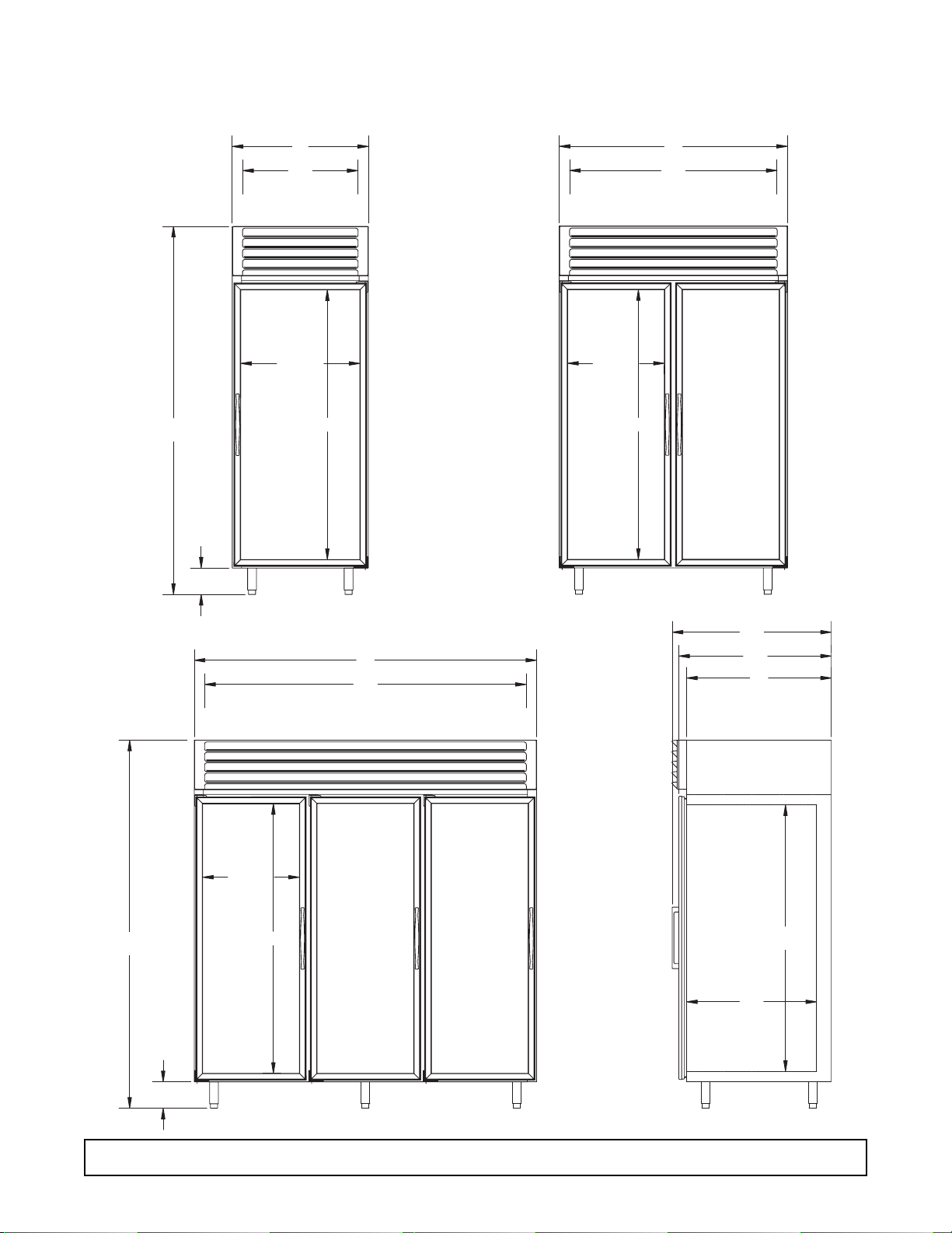
10 DIMENSIONAL DRAWINGS - Top Mount (Glass Door) Models
Low Temperature, Top Mount, Glass Pull Door Freezers
Dimensional Drawings
83w
61
GLASS
TYP.
52
474
INTERIOR
31
4
26
INTERIOR
26 w
GLASS
61
GLASS
6
21 d
GLASS
TYP.
83w
21 d
GLASS
TYP.
61
GLASS
TYP.
78
734
INTERIOR
364
34w
33
60d
INTERIOR
29d
INTERIOR
6
SIDE VIEW
Page 13

Low Temperature, Top Mount, Glass Pull Door Freezers
Specifications
SPECIFICATIONS - Top Mount Models 11
Specification 1-Door 2-Door 3-Door
Compressor Mount Top Top Top
Temperature Range 0° to 20° (-18° to 29°C) 0° to 20° (-18° to 29°C) 0° to 20° (-18° to 29°C)
Number of Doors 1 2 3
Door Construction Triple Pane Triple Pane Triple Pane
Hinge Type Torsion Bar Torsion Bar Torsion Bar
Number of Shelves 4 8 12
Shelf Type Cantilever Epoxy Coated Cantilever Epoxy Coated Cantilever Epoxy Coated
Shelf Adj. 3/4" 3/4" 3/4"
Insulation - CFC-Free Foam-in-Place Urethane Foam-in-Place Urethane Foam-in-Place Urethane
Wall Thickness 2 3/8" 2 3/8" 2 3/8"
Capacity - Gross 27.3 ft.
3
49.1 ft.
3
76.2 ft.
3
Capacity (1/2 gal. ice cream) 183 366 549
Shipping Weight (Approx.) 520 lbs. 760 lbs. 1010 lbs.
Compressor Size. 3/4 hp 1 hp 1 1/2 hp
Condenser Type Fin & Tube Forced Air Fin & Tube Forced Air Fin & Tube Forced Air
Evaporator Type Fin & Tube Forced Air Fin & Tube Forced Air Fin & Tube Forced Air
Refrigerant Type R-404A R-404A R-404A
Refrigerant Control Expansion Valv e Expansion Valve Expansion Valv e
Amp Rating 16 14.6 16
Electrical Specs. (V / Hz / Ph) 115 / 60 / 1 115 / 208-230 / 60 / 1 115 / 208-230 / 60 / 1
NSF NSF7 NSF7 NSF7
UL & CSA Listed Yes Yes Yes
Interior Finish Baked Enamel, Covered Corners Baked Enamel, Covered Corners Baked Enamel, Covered
Corners
Exterior Finish Baked Enamel Baked Enamel Baked Enamel
Sign Panel Optional Optional Optional
Lighting
2 Insul. 1500 Milliamp Fluor.Lamps 3 Insul. 1500 Milliamp Fluor.Lamps 4 Insul. 1500 Milliamp Fluor.Lamps
Page 14
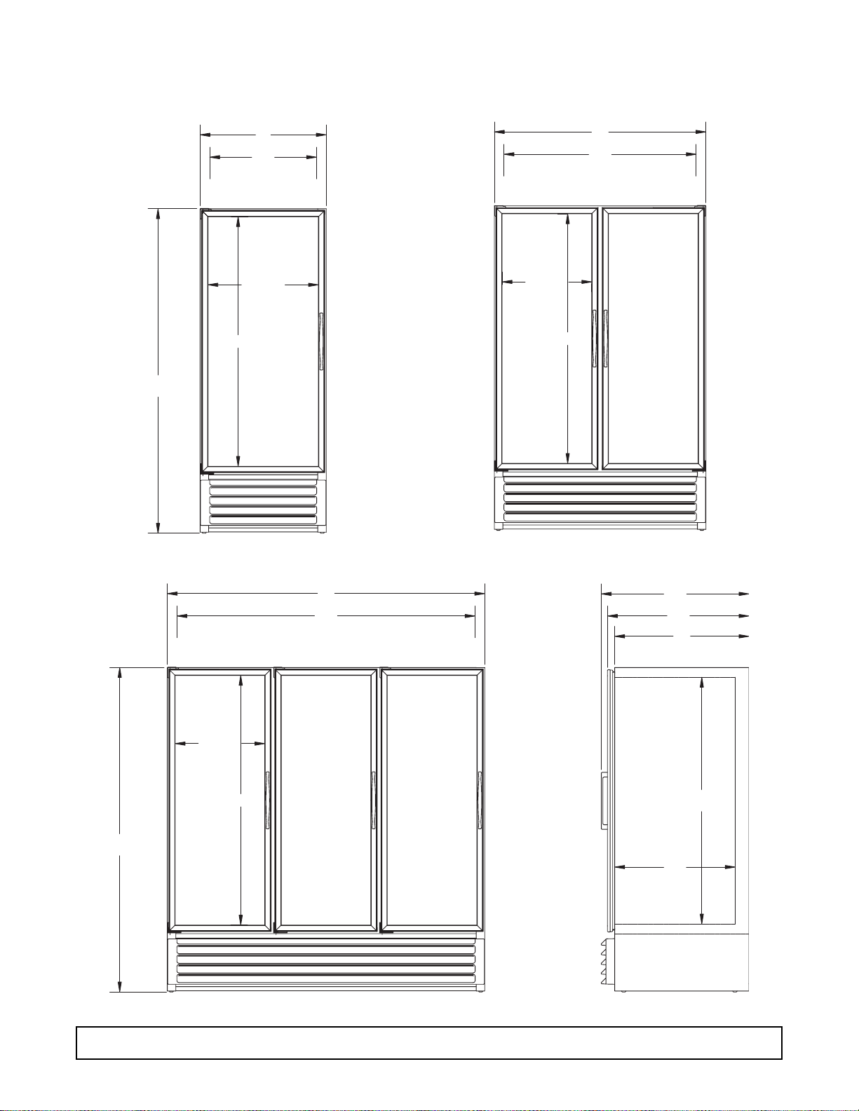
12 DIMENSIONAL DRAWINGS - Bottom Mount (Glass Door) Models
Low Temperature, Bottom Mount, Glass Pull Door Freezers
Dimensional Drawings
79 w
61
GLASS
31
264
INTERIOR
26 w
GLASS
21 d
GLASS
TYP.
61
GLASS
TYP.
52
474
INTERIOR
79w
21 d
GLASS
TYP.
61
GLASS
TYP.
78
734
INTERIOR
364
34w
33
INTERIOR
29d
INTERIOR
60d
SIDE VIEW
Page 15

Low Temperature, Bottom Mount, Glass Pull Door Freezers
Specifications
SPECIFICATIONS - Bottom Mount Models 13
Specification 1-Door 2-Door 3-Door
Compressor Mount Bottom Bottom Bottom
Temperature Range 0° to -20° (-18° to -29°C) 0° to -20° (-18° to -29°C) 0° to -20° (-18° to -29°C)
Number of Doors 1 2 3
Door Construction Triple Pane Triple Pane Triple Pane
Hinge Type Torsion Bar Torsion Bar Torsion Bar
Insulation - CFC-Free Foam-in-Place Urethane Foam-in-Place Urethane Foam-in-Place Urethane
Wall Thickness 2 3/8" 2 3/8" 2 3/8"
Capacity - Gross 27.3 ft.
3
49.1 ft.
3
76.2 ft.
3
Shipping Weight (Approx.) 516 lbs. 705 lbs. 984 lbs.
Compressor Size 3/4 hp 1 hp 1 1/2 hp
Condenser Type Fin & Tube Forced Air Fin & Tube Forced Air Fin & Tube Forced Air
Evaporator Type Fin & Tube Forced Air Fin & Tube Forced Air Fin & Tube Forced Air
Refrigerant Type R-404A R-404A R-404A
Refrigerant Control Expansion Valv e Expansion Valve Expansion Valv e
Amp Draw 14.6 13.0 16.0
Electrical Specs. (V / Hz / Ph) 115 / 60 / 1 208/230-60-1 208/230-60-1
NSF NSF7 NSF7 NSF7
UL & CSA Listed Yes Yes Yes
Interior Finish Baked Enamel, Covered Corners Baked Enamel, Covered Corners Baked Enamel, Covered
Corners
Exterior Finish Baked Enamel Baked Enamel Baked Enamel
Lighting
2 Insul. 1500 Milliamp Fluor.Lamps 3 Insul. 1500 Milliamp Fluor.Lamps 4 Insul. 1500 Milliamp Fluor.Lamps
Electrical Information 20 Amp Service Cord 20 Amp Service Cord 20 Amp Ser vice Cord
Page 16

52
83w
61
61
6
GLASS
GLASS
26 w
31
INTERIOR
21 d
GLASS
TYP.
GLASS
TYP.
474
INTERIOR
734
78
INTERIOR
61
21 d
GLASS
GLASS
TYP.
TYP.
29d
60d
INTERIOR
33
364
34w
INTERIOR
83w
SIDE VIEW
6
26
4
14 DIMENSIONAL DRAWINGS - Top Mount (Solid Door) Models
Low Temperature, Top Mount, Solid Pull Door Freezers
Dimensional Drawings
Page 17
Low Temperature, Top Mount, Solid Pull Door Freezers
Specifications
SPECIFICATIONS - Bottom Mount Models 15
Specification 1-Door 2-Door 3-Door
Compressor Mount Top Top Top
Temperature Range 0° to -20° (-18° to -29°C) 0° to -20° (-18° to -29°C) 0° to -20° (-18° to -29°C)
Number of Doors 1 2 3
Door Construction Foam-In-Place Foam-In-Place Foam-In-Place
Hinge Type Camlift / Spring Camlift / Spring Camlift / Spring
Number of Shelves 4 x 1 bottom rack 8 x 2 bottom racks 12 x 3 bottom racks
Shelf Type
Cantilever, Epoxy Coated Steel Wire Cantilever, Epoxy Coated Steel Wire Cantilever, Epoxy Coated Steel Wire
Shelf Adj. 3/4" 3/4" 3/4"
Insulation - CFC-Free Foam-in-Place Urethane Foam-in-Place Urethane Foam-in-Place Urethane
Wall Thickness 2 3/8" 2 3/8" 2 3/8"
Capacity - Gross 27.3 ft.
3
49.1 ft.
3
76.2 ft.
3
Shipping Weight (Approx.) 460 lbs. 660 lbs. 870 lbs.
Compressor Size 1/2 hp 1/2 hp 3/4 hp
Condenser Type Fin & Tube Forced Air Fin & Tube Forced Air Fin & Tube Forced Air
Evaporator Type Fin & Tube Forced Air Fin & Tube Forced Air Fin & Tube Forced Air
Refrigerant Type R-404A R-404A R-404A
Refrigerant Control Expansion Valv e Expansion Valve Expansion Valv e
Amp Draw (80° Running) 7.3 13.0 16.0
Electrical Specs. (V / Hz / Ph) 115 / 60 / 1 115/60/1 115/60/1
NSF NSF7 NSF7 NSF7
UL & CSA Listed Yes Yes Yes
Interior Finish Baked Enamel, Covered Corners Baked Enamel, Covered Corners Baked Enamel, Covered
Corners
Electrical Information 15 Amp Service Cord 20 Amp Service Cord 20 Amp Ser vice Cord
Page 18

Low Temperature, Top Mount, Solid Pull Door
Hardening/Flash Freezers -Specifications
Specification 1-Door Quad Door Quad Door
Hardening Cabinet Hardening Cabinet Flash Freezer
Compressor Mount Top - Top Top
Temperature Range 0° to -30° (-18° to -34°C) 0° to -30° (-18° to -34°C) 0° to -40° (-18° to -40°C)
Number of Doors 1 Outer, 2 Inner 4 Outer 4 Outer
Door Construction
Foam-In-Place on Outer Door
Foam-In-Place Foam-In-Place
Hinge Type Camlift / Spring Camlift / Spring Camlift / Spring
Number of Shelves 4 x 1 bottom rack 8 x 2 bottom racks 8 x 2 bottom racks
Shelf Type
Cantilever, Epoxy Coated Steel Wire Cantilever, Epoxy Coated Steel Wire Cantilever, Epoxy Coated Steel Wire
Shelf Adj. 3/4" 3/4" 3/4"
Insulation - CFC-Free Foam-in-Place Urethane Foam-in-Place Urethane Foam-in-Place Urethane
Wall Thickness 2 3/8" 2 3/8" 2 3/8"
Capacity - Gross 27.3 ft.
3
49.1 ft.
3
41.9 ft.
3
Shipping Weight (Approx.) 460 lbs. 660 lbs. 660 lbs.
Compressor Size 1/2 hp 3/4 hp 11/2 hp
Condenser Type Fin & Tube Forced Air Fin & Tube Forced Air Fin & Tube Forced Air
Evaporator Type Fin & Tube Forced Air Fin & Tube Forced Air Fin & Tube Forced Air
Refrigerant Type R-404A R-404A R-404A
Refrigerant Control Expansion Valv e Expansion Valve Expansion Valv e
Amp Draw (80° Running) 11.5 16.0 7.4
Electrical Specs. (V / Hz / Ph) 115 / 60 / 1 115/60/1 115/208-230/60/1
NSF NSF7 NSF7 NSF7
UL & CSA Listed Yes Yes Yes
Interior Finish Baked Enamel, Covered Corners Baked Enamel, Covered Corners Baked Enamel, Covered
Corners
Exterior Finish Baked Enamel Baked Enamel Baked Enamel
Electrical Information 20 Amp Service Cord 20 Amp Service Cord Conduit Connected
w/NEMA 5-20P Plug w/NEMA 5-20P Plug max. fuse size 15A
16 SPECIFICATIONS - Top Mount (Solid Door) Models
Page 19

SECTION II
Electrical
and
Refrigeration
Page 20

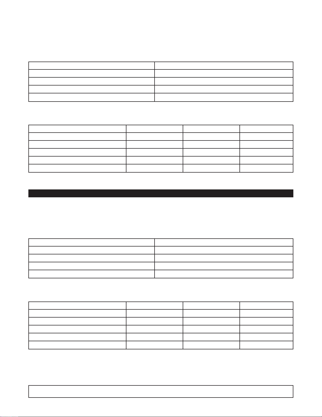
Compressor Model Number Copeland KAJB-007E-1AA
Cabinet V olts 115/60/1
Expansion Device Sporlan Y1232-FBS 1/4
Charge Refrig.Type / Oz. / Grams 404A / 18 oz. / 510 grams
ELECTRICAL & REFRIGERATION SPECIFICATIONS
Low Temp., Glass, 1-Door Freezers
SYSTEM COMPONENTS
AMBIENT 70°F / 21.1°C 80°F / 27°C 90°F / 32.5°C
Cavity Temp. (F/C) -6 / -21 -7 / -22 -9 / -23
Suction Pressure (PSIG / Kpa) 4.0 / 27.6 4.0 / 27.6 5.0 / 34
Discharge Pressure (PSIG / Kpa) 201/1385 233/1537 247/1703
Compressor Amps 9.9 9.6 9.8
Total Refrigeration Amps 13.7 13.4 13.6
SYSTEM PERFORMANCE
NOTE: REFER TO SERIAL DATA PLATE FOR REFRIGERANT TYPE & CHARGE.
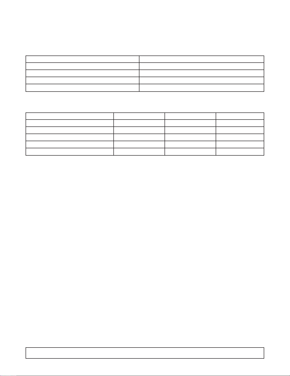
Compressor Model Number Americold HP121-1-3087
Recommended Operating Temp. Range (F/C) 0°F to -20°F (-18°C to -29°C)
Cabinet V olts 115/60/1
Expansion Device Sporlan Y1232-FBS 1/4
Charge Refrig.Type / Oz. / Grams R404A / 22 oz. / 623.7 grams
SYSTEM COMPONENTS
AMBIENT 70°F / 21.1°C 80°F / 27°C 90°F / 32.5°C
Cavity Temp. (F/C) -4 / -20 -5 / -21 -6 / -7
Suction Pressure (PSIG / Kpa) 12 8.7 12.5
Discharge Pressure (PSIG / Kpa) 194 210 220
Compressor Amps 2.9 2.7 2.8
Total Refrigeration Amps 5.4 5.4 5.4
SYSTEM PERFORMANCE
Low Temp., Solid, 1-Door Freezer
ELECTRICAL / REFRIGERATION SPECIFICATIONS 19
Page 21

Compressor Model Number Copeland KALB-010E-CAV
Recommended Operating Temp. Range (F/C) 0°F to -20°F (-18°C to -29°C)
Cabinet V olts 115/208-230/60/1
Expansion Device Sporlan Y1232-FBS 1/4
Charge Refrig.Type / Oz. / Grams R404A / 29 oz. / 822.9 grams
ELECTRICAL & REFRIGERATION SPECIFICATIONS
Low Temp., Glass, 2-Door Freezers
SYSTEM COMPONENTS
AMBIENT 70°F / 21.1°C 80°F / 27°C 90°F / 32.5°C
Cavity Temp. (F/C) -6 / -21 -6.5 / -21 -7.5 / -22
Suction Pressure (PSIG / Kpa) 6.7 / 46 7.0 / 48 7.6 / 52
Discharge Pressure (PSIG / Kpa) 213/1468 223/1537 250/1723
Compressor Amps 5.0 5.0 5.0
Total Refrigeration Amps 6.0 6.0 6.0
SYSTEM PERFORMANCE
NOTE: REFER TO SERIAL DATA PLATE FOR REFRIGERANT TYPE & CHARGE.
Compressor Model Number Copeland KAGB-005E-IAA
Recommended Operating Temp. Range (F/C) 0°F to -20°F (-18°C to -29°C)
Cabinet V olts 115/60/1
Expansion Device Sporlan Y1232-FBS 1/4
Charge Refrig.Type / Oz. / Grams R404A / 22 oz. / 623.7 grams
SYSTEM COMPONENTS
AMBIENT 70°F / 21.1°C 80°F / 27°C 90°F / 32.5°C
Cavity Temp. (F/C) -3 / -19 -4 / -20 -4.5 / -21
Suction Pressure (PSIG / Kpa) 9 / 62 9 / 62 9.5 / 65
Discharge Pressure (PSIG / Kpa) 222 / 1530 240 / 1654 265 / 1827
Compressor Amps 8.0 8.0 8.0
Total Refrigeration Amps 11.0 11.0 11.0
SYSTEM PERFORMANCE
Low Temp., Solid, 2-Door Freezer
20 ELECTRICAL / REFRIGERATION SPECIFICATIONS
Page 22
Compressor Model Number Copeland KATB-015E-CAV
Recommended Operating Temp. Range (F/C) 0°F to -20°F (-18°C to -29°C)
Cabinet V olts 115/208-230/60/1
Expansion Device Sporlan Y1232-FBS 1/2
Charge Refrig.Type / Oz. / Grams R404A / 42 oz. / 1190.7 grams
ELECTRICAL & REFRIGERATION SPECIFICATIONS
Low Temp., Glass, 3-Door Freezers
SYSTEM COMPONENTS
AMBIENT 70°F / 21.1°C 80°F / 27°C 90°F / 32.5°C
Cavity Temp. (F/C) -7 / -22 -8 / -22 -14 / -26
Suction Pressure (PSIG / Kpa) 5.0 / 34 6.5 / 44 8.5 / 58
Discharge Pressure (PSIG / Kpa) 191/1316 223/1606 262/1806
Compressor Amps 6.5 6.9 7.1
Total Refrigeration Amps 8.2 8.5 8.7
SYSTEM PERFORMANCE
NOTE: REFER TO SERIAL DATA PLATE FOR REFRIGERANT TYPE & CHARGE.
Compressor Model Number Copeland KAJB-007E-IAA
Recommended Operating Temp. Range (F/C) 0°F to -20°F (-18°C to -29°C)
Cabinet V olts 115/60/1
Expansion Device Sporlan Y1232-FBS 1/4
Charge Refrig.Type / Oz. / Grams 404A / 25 oz. / 708.75 grams
SYSTEM COMPONENTS
AMBIENT 70°F / 21.1°C 80°F / 27°C 90°F / 32.5°C
Cavity Temp. (F/C) -5 / -21 -6 / -21 -7 / -22
Suction Pressure (PSIG / Kpa) 7 / 48.3 7.5 / 51.7 8 / 55.2
Discharge Pressure (PSIG / Kpa) 205 / 1413 245 / 1689 270 / 1861
Compressor Amps 8.5 8.5 8.5
Total Refrigeration Amps 12.9 12.9 12.9
SYSTEM PERFORMANCE
Low Temp., Solid, 3-Door Freezer
ELECTRICAL / REFRIGERATION SPECIFICATIONS 21
Page 23

Compressor Model Number Copeland KAGB-005E-IAA
Recommended Operating Temp. Range (F/C) 0°F to -40°F (-18°C to -40°C)
Cabinet V olts 115/60/1
Expansion Device Sporlan Y1232-FBS 1/4
Charge Refrig.Type / Oz. / Grams R404A / 22 oz. / 623.7 grams
ELECTRICAL & REFRIGERATION SPECIFICATIONS
Hardening Cabinet, Solid, 1-Door Freezer
SYSTEM COMPONENTS
AMBIENT 70°F / 21.1°C 80°F / 27°C 90°F / 32.5°C
Cavity Temp. (F/C) -20 / -29 -20 / -29 -20 / -29
Suction Pressure (PSIG / Kpa) 4.0 / 27 6.0 / 41 6.6 / 46
Discharge Pressure (PSIG / Kpa) 180.0/1241 228/1572 234/1613
Compressor Amps 7.8 7.9 7.8
Total Refrigeration Amps 10.3 10.3 10.2
SYSTEM PERFORMANCE
Compressor Model Number Copeland KAJB-007E-IAA
Recommended Operating Temp. Range (F/C) 0°F to -40°F (-18°C to -40°C)
Cabinet V olts 115/60/1
Expansion Device Sporlan Y1232-FBS 1/4
Charge Refrig.Type / Oz. / Grams R404A / 22 oz. / 623.7 grams
ELECTRICAL & REFRIGERATION SPECIFICATIONS
Hardening Cabinet, Solid, Quad Door Freezer
SYSTEM COMPONENTS
AMBIENT 70°F / 21.1°C 80°F / 27°C 90°F / 32.5°C
Cavity Temp. (F/C) -16 / -27 -18 / -28 -18 / -28
Suction Pressure (PSIG / Kpa) 2.6 / 18 3.6 / 25 4.0 / 28
Discharge Pressure (PSIG / Kpa) 200/1379 224/1544 245/1689
Compressor Amps 7.9 7.9 7.8
Total Refrigeration Amps 11.1 11.0 10.9
SYSTEM PERFORMANCE
NOTE: REFER TO SERIAL DATA PLATE FOR REFRIGERANT TYPE & CHARGE.
22 ELECTRICAL / REFRIGERATION SPECIFICATIONS
Page 24
Compressor Model Number KALB-015E-CAV
Recommended Operating Temp. Range (F/C) 0°F to -40°F (-18°C to -40°C)
Cabinet V olts 115/208-230/60/1
Expansion Device Sporlan Y1232-FBS 1/2
Charge Refrig.Type / Oz. / Grams R404A / 29 oz. / 822.15 grams
ELECTRICAL & REFRIGERATION SPECIFICATIONS
Flash Freezer, Solid, Quad Door
SYSTEM COMPONENTS
AMBIENT 70°F / 21.1°C 80°F / 27°C 90°F / 32.5°C
Cavity Temp. (F/C) -19 -19 -20
Suction Pressure (PSIG / Kpa) 3.3 3.7 4.3
Discharge Pressure (PSIG / Kpa) 193 219 252
Compressor Amps 5.7 5.6 5.5
Total Refrigeration Amps 9.5 9.5 5.5
SYSTEM PERFORMANCE
ELECTRICAL / REFRIGERATION SPECIFICATIONS 23
Page 25

Door Heater 94.4 watts
115V 140 ohms 168 ohms 168 ohms
230V 477 ohms 585 ohms 585 ohms
110.9 watts
Perimeter Heater 63.8 watts
115V 207 ohms 230 ohms 230 ohms
230V 746 ohms 782 ohms 782 ohms
70.9 watts
Condensate Heater 174 watts 174 watts 174 watts
115V 76 ohms 76 ohms 76 ohms
230 V 257 ohms 257 ohms 257 ohms
205.8 watts
Drain Heater 6.0 watts 6.0 watts 6.0 watts
115V 2204 ohms 2204 ohms 2204 ohms
230V 7704 ohms 7704 ohms 7704 ohms
6.8 watts
Defrost Heater Solid Glass Solid Glass Solid Glass
16.5 ohms 16.5 ohms 16.5 ohms 46 ohms 10.6 ohms 30 ohms
800 watts 800 watts 800 watts 1250 watts 1250 watts 1927 watts
115 volts 115 volts 115 volts 240 volts 115 volts 240 volts
Lamp F60T10CWHO F60T10CWHO F6010CWHO
Evap. Fan Delay (Non-Pulse) Close 32° / Open 52° Close 32° / Open 52° Close 32° / Open 52°
Defrost Termination(Non-Pulse) Close 30° / Open 60° Close 30° / Open 60° Close 30° / Open 60°
Defrost Time/Temp
Failsafe 40 min. 40 min 40 min.
Hardening Cabinets
Defrost Time/Time 30 min. 30 min. N/A
Hardening Cabinet 73.5 watts
Center Mullion
Vertical N/A N/A
115V 179 ohms
230V 719 ohms
Hardening Cabinet 8.75 watts
Mullion 1511 ohms
115V 1548 volts N/A
230V 6194 ohms
CPR V alv e
4&6 10PSIG 10PSIG 10PSIG
GENERAL LOW TEMPERATURE FREEZER
COMPONENT SPECIFICATIONS
1-DOOR 2-DOOR 3-DOOR
24 ELECTRICAL / REFRIGERATION SPECIFICATIONS
Page 26

WIRING DIAGRAM REFERENCE
WIRING DIAGRAM REFERENCE 25
CONTROL
PANEL
LIGHTS,
FLUORESCENT SOLENOID
INCAND LIGHT,
RACEWAY EVAPORATOR
ANTI-SWEAT
HTR, RACEWAY
WIRING DIAGRAM REFERENCE
DOOR SWITCH,
RACEWAY
BT30CW-EXPR 26-0983-00
BT30CWFMS-2 00-0430-00
BT30FS-4 00-0051-00 00-0071-00 00-0062-00 00-0061-03 00-0061-04 00-0061-05 00-0050-02 00-0058-01
BT50FS-4 00-0051-00 00-0072-00 00-0062-00 00-0061-02 00-0061-04 00-0061-05 00-0050-02 00-0058-01
BT80FS-4 00-0051-00 00-0068-00 00-0062-00 00-0061-03 00-0061-04 00-0061-05 00-0050-02 00-0058-01
BTL30FS-4 00-0051-00 00-0072-00 00-0062-00 00-0061-04 00-0061-05 00-0050-02 00-0058-01
BTQ50FSHD-4 00-0054-00 00-0069-00 00-0063-00 00-0061-04 00-0050-02 00-0058-01
ST30FSBB-4 00-0051-00 00-0071-00 00-0062-00 00-0061-03 00-0061-04 00-0061-05 00-0050-02 00-0017-11
STL30FSBB-4 00-0051-00 00-0072-00 00-0062-00 00-0061-04 00-0061-05 00-0050-02 00-0017-11
T30HSP-4 00-0051-00 00-0072-00 00-0062-00 00-0061-04 00-0050-02
T30LGP-5 00-0107-00 00-0068-00 00-0109-00 00-0061-01 00-0061-04 00-0050-05 00-0067-01
T30LGPE-5 00-0107-00 00-0069-00 00-0112-00 00-0061-01 00-0061-04 00-0050-05 00-0067-04
T30LGPRBR-5 00-0107-00 00-0109-00 00-0061-01 00-0061-04 00-0050-05 00-0067-01 00-0060-00
T30LSP-5 00-0107-00 00-0071-00 00-0109-00 00-0061-01 00-0061-04 00-0050-05
T30LSPHD-5 00-0107-00 00-0072-00 00-0109-00 00-0061-01 00-0061-04 00-0050-05
T50HSQHP-4 00-0054-00 00-0069-00 00-0063-00 00-0061-04 00-0050-02
T50HSQL-4 00-0051-00 00-0072-00 00-0062-00 00-0061-04 00-0050-02
T50LGP-5 00-0108-00 00-0113-00 00-0110-00 00-0061-02 00-0061-04 00-0050-05 00-0067-02
T50LGPE-5 00-0107-00 00-0069-00 00-0112-00 00-0061-02 00-0061-04 00-0050-05 00-0067-04
T50LGPHD-5 00-0108-00 00-0113-00 00-0110-00 00-0061-02 00-0061-04 00-0050-05 00-0067-02
T50LGPR-5 00-0108-00 00-0110-00 00-0061-02 00-0061-04 00-0050-05 00-0067-02 00-0060-00
T50LSP-5 00-0107-00 00-0072-00 00-0109-00 00-0061-02 00-0061-04 00-0050-05
T50LSPR-5 00-0107-00 00-0109-00 00-0061-02 00-0061-04 00-0050-05 00-0060-00
T80LGP-5 00-0108-00 00-0113-00 00-0110-00 00-0061-03 00-0061-04 00-0050-05 00-0067-03
T80LGPE-5 00-0107-00 00-0069-00 00-0112-00 00-0061-03 00-0061-04 00-0050-05 00-0067-04
T80LGPR-5 00-0108-00 00-0110-00 00-0061-03 00-0061-04 00-0050-05 00-0067-03 00-0060-00
T80LSP-5 00-0107-00 00-0068-00 00-0109-00 00-0061-03 00-0061-04 00-0050-05
ULG30BF-5 00-0107-00 00-0069-00 00-0112-00 00-0061-02 00-0061-04 00-0050-05 00-0067-04
ULG30BS-5 00-0107-00 00-0068-00 00-0109-00 00-0061-01 00-0061-04 00-0050-05 00-0067-01
ULG50BC-5 00-0108-00 00-0113-00 00-0110-00 00-0061-02 00-0061-04 00-0050-05 00-0067-02
ULG50BF-5 00-0107-00 00-0069-00 00-0112-00 00-0061-01 00-0061-04 00-0050-05 00-0067-04
ULG50RD-5 00-0108-00 00-0110-00 00-0061-02 00-0061-04 00-0050-05 00-0067-02 00-0060-00
ULG80BC-5 00-0108-00 00-0113-00 00-0110-00 00-0061-03 00-0061-04 00-0050-05 00-0067-03
ULG80BF-5 00-0107-00 00-0069-00 00-0112-00 00-0061-03 00-0061-04 00-0050-05 00-0067-04
ULG80RD-5 00-0108-00 00-0110-00 00-0061-03 00-0061-04 00-0050-05 00-0067-03 00-0060-00
MODELS LADDER COMPRESSOR ELECT BOX
ULS30US-5 00-0107-00 00-0109-00 00-0061-03 00-0061-04 00-0050-05 00-0060-00
Page 27

LADDER DIAGRAM - 00-0051-00
26 WIRING DIAGRAM
Page 28

LADDER DIAGRAM - 00-0054-00
WIRING DIAGRAM 27
Page 29

LADDER DIAGRAM - 00-0107-00
28 WIRING DIAGRAM
Page 30

LADDER DIAGRAM - 00-0108-00
WIRING DIAGRAM 29
Page 31

COMPRESSOR WIRING DIAGRAM - 00-0068-00
30 WIRING DIAGRAM
Page 32

COMPRESSOR WIRING DIAGRAM - 00-0069-00
WIRING DIAGRAM 31
Page 33

COMPRESSOR WIRING DIAGRAM - 00-0071-00
32 WIRING DIAGRAM
Page 34

COMPRESSOR WIRING DIAGRAM - 00-0072-00
WIRING DIAGRAM 33
Page 35

COMPRESSOR WIRING DIAGRAM - 00-0113-00
34 WIRING DIAGRAM
Page 36

ELECTRICAL BOX WIRING DIAGRAM - 00-0062-00
WIRING DIAGRAM 35
Page 37

ELECTRICAL BOX WIRING DIAGRAM - 00-0063-00
36 WIRING DIAGRAM
Page 38

ELECTRICAL BOX WIRING DIAGRAM - 00-0109-00
WIRING DIAGRAM 37
Page 39

ELECTRICAL BOX WIRING DIAGRAM - 00-0110-00
38 WIRING DIAGRAM
Page 40

ELECTRICAL BOX WIRING DIAGRAM - 00-0112-00
WIRING DIAGRAM 39
Page 41

RACEWAY WIRING DIAGRAM - 00-0061-*
40 WIRING DIAGRAM
Page 42

EVAPORATOR WIRING DIAGRAM - 00-0050-*
WIRING DIAGRAM 41
Page 43

FLUORESCENT LIGHT WIRING DIAGRAM - 00-0067-*
42 WIRING DIAGRAM
Page 44

SOLENOID WIRING DIAGRAM - 00-0060-*
WIRING DIAGRAM 43
Page 45

CONTROL PANEL WIRING DIAGRAM - 00-0071-11
44 WIRING DIAGRAM
Page 46

CONTROL PANEL WIRING DIAGRAM - 00-0058-*
WIRING DIAGRAM 45
Page 47

SECTION III
Maintenance
and
Repair
The manufacturer requires compliance to all CGC
reclamation laws by service companies engaging
in system processing.
Page 48

WARNING
To avoid the possibility of an electrical shock,turn
OFF the thermostat and unplug the power cord of
the cabinet before cleaning or touching electrical
connections or parts.
Page 49

MAINTENANCE & REPAIR
PRE-SERVICE CHECK LIST
You may avoid the cost and inconvenience of an
unnecessary product call by first reviewing this check list
of the most frequently encountered situations that are
not the result of defective workmanship or materials.
COMPRESSOR RUNS TOO MUCH
1. A refrigerated cabinet automatically compensates for
product loading by running longer and more often.
Before calling for service, check running time for at
least one hour the first thing in the morning (before
store traffic starts).
2. Be sure the doors seal. A faulty gasket seal will cause
increased running time.
3. Check the room temperature.The warmer the room,
the more the compressor will run.
4. Check the condenser to be sure the face is clean.Dirt
and lint will raise pressures and increase running
time.Use a brush or vacuum to clean the condenser.
5. Be sure condenser fan operates.
6. Check to see that evaporator fans are running.
7. If product is too hard (cold), try setting the
Temperature Control (thermostat) warmer. This will
result in warmer cabinet temperature and reduced
running time.
8. Check insufficient ventilation to condenser.
CABINET DOES NOT OPERATE
1. Be sure cabinet is plugged in.
2. Check that breakers or fuses are good and all
switches in the supply line are ON.
3. Be sure that cabinet Master Power Supply Switch is
ON.
4. If you are in an area with voltage problems, try
shutting off all non-essential electrical equipment.
LIGHT IS OFF
1. If the cabinet is operating, be sure the lamp is
properly seated in sockets.
2. If cabinet is not running, check that Master Power
Supply Switch and Light Switch are ON, fuses are
okay, no switch in the supply is OFF, and that the
cabinet is plugged in.
CUSTOMER COMPLAINT ON STORED
PRODUCT
1. Check cleaning solutions used inside cabinet.
2. Check cleaning solutions, paint, or other
contaminants used in store maintenance.
3. Sometimes the ingredients used in some products or
containers will contaminate other products.
4. Be sure to follow a weekly schedule for cleaning
cabinet interior.
SERVICE
In the event of a malfunction, damage to the cabinet,
or if the cabinet requires service beyond the items in
the “Pre-Service Checklist,” contact your local service
company or the dealer from whom the cabinet was
purchased.
POWER FAILURE
Do not open the cabinet doors unnecessarily if power is
cut off due to electrical failure.The cabinet will start up if
the power supply returns, but will require sufficient time
to reach maximum cold storage performance.
CABINET FAILURE
1. If the cabinet has stopped operating, check that the
cabinet is securely plugged in and turned on.Contact
a licensed electrician to locate and correct any power
supply problems.
2. Do not open the cabinet doors unnecessarily.
3. Provisions for other storage of the product may be
required to prevent spoilage.
If you call for service, describe your problem and giv e the
following information to the service representative:
Cabinet Model No. ____________________________
Part No. ____________________________________
Serial No. __________________________________
(These numbers are located on a silver serial number
rating plate in the upper left side of the cabinet interior.)
MAINTENANCE & REPAIR 49
Page 50

TOOLS:
To provide full ser vice diagnostics and repairs on these
cabinets, the following tools are needed:
A Multimeter
An Electronic Leak Detector
An Electronic Micron Gauge
A Vacuum Pump capable of pulling to 50 microns
Four Hand Valves
A Compound Gauge Set
A cylinder of nitrogen with a regulator capable of 10 to
400 pounds.
Standard refrigeration hand tools, e.g.: wrenches, tube
cutter, swage and flare tools, wire strippers, wire crimp.
ers, wire cutters, slot and phillips head screwdrivers.
PRODUCT HISTORY
The first rule in servicing a refrigeration system is to
determine if the problem is an electrical or mechanical
failure.
First, try to obtain the product’s history of operation
from the customer.This will help identify the source of
the problem.
Good facts from the cabinet user can help identify
whether the problem is electrical, within the
refrigeration system, or a “misapplication by the user”.
Get the history of operation and failure by asking these
questions:
1) Were there any brown-outs or power outages that
they are aware of?
2) Is the cabinet on a dedicated circuit?
3) Has any other equipment in this area had
operational problems?
4) When was the last time the cabinet’s operation was
confirmed as working properly?
5) When was a problem noticed?
6) How long has the equipment run without this
problem? (Years? Weeks? Days? Hours?)
7) Was anything tried prior to your arrival?
The refrigeration system should only be entered if it is
absolutely necessary. It is critical that a clean,
uncontaminated system be maintained.
If a system is unable to reach the proper operating
temperature, a test of the unit’s mechanical
refrigeration components is required.
COMPRESSOR EFFICIENCY TEST
To test the compressor, place compound gauge on the
compressor’s suction port.
While the compressor is running, close off the suction
line so that only the port and valve are part of the
compressor’s low side.
When the valve is closed and vacuum has started, time
how long it takes to pull the compressor’s low side to its
lowest possible vacuum.
Compressors used on these cabinets should be capable
of pulling at least 20 to 22 inches of vacuum in less than
40 seconds.
Next, shut off the compressor and watch the gauge. A
one or two inch rise in pressure is acceptable, since a
small amount of freon may remain on the low side of the
compressor, after which the reading should stabilize.
If the pressure continues to rise, the discharge reeds in
the valve head ha ve f ailed, allowing high pressure gas to
return to the compressor.
If the compressor pulls less than 20 inches, the suction
reeds have failed.
If the compressor takes longer than 40 seconds to pull
to its ultimate low vacuum, one or both cylinders are not
functioning as they should. Any reading less than these
will require replacement of the compressor.
ENTERING THE SYSTEM
Entering the system should only be done as a last
resort. Extreme care must be used no matter what the
reason for entering the system. Of course there are
times when it cannot be avoided, such as component or
compressor replacement, or a leak within the system.
The system must also be entered any time you need to
obtain the operating pressures. Again, use extreme
caution to avoid any possible contamination.
Cabinets that use hermetic compressors typically do not
have valve ports, so therefore process stubs for both
suction and discharge sides of the system were added.
Line taps should only be used to obtain pressure
readings, and not for the reprocessing of the system.
The opening of a line tap is too restrictive for the
pressure of vacuum procedures.
On a hermetic compressor system, once you have
determined that reprocessing a system is required,
recover refrigerant and remove the line taps.
50 MAINTENANCE & REPAIR
Page 51

Install hand valves at the process stub ends. Hand
valves will be less restrictive to flow because of a larger
opening. They will also be easier to use during repair
procedures.
EVACUATION
Once the system has been cleaned and components
have been replaced, you are ready to initiate the final
servicing procedures necessary to achieve proper
cabinet operation. Drier should be replaced prior to
system processing.
Pull an evacuation to approximately 50 microns.
CHARGING
You should use a charging cylinder to measure in the
correct amount of refrigerant.The charging methods are:
1. Add the refr igerant to the system until you reach a
balanced pressure. This will give you an
approximate static charge.
2. Weigh in the refrigerant using a scale calibrated in
ounces.
The cabinet’s operation is now ready to be tested. A
final check of the refrigeration lines should be made
before running the cabinet.
Be sure the refrigeration lines are not kinked or
rubbing against each other.
Also check that the door seals properly. An air leak will
affect proper operation, and the cabinet’s ability to
reach its coldest temperature.
Run the cabinet at both 100% run, and a cycling
temperature for at least 24 hours. If the temperature
and pressures are correct, the system can be
considered repaired.
Hermetic systems should now have their process
stubs pinched off, hand valves removed and the ends
brazed shut.
MAINTENANCE & REPAIR 51
Page 52

COMPRESSOR INSTALLATION & MAINTENANCE
TO CHANGE THE COMPRESSOR:
1. Disconnect the power supply to the cabinet.
2. Disconnect the power supply leads at the
compressor.
3. Disconnect wires to relay and capacitors.
4. Remove relay and starting capacitor and install on
new compressor.
5. Remove defective compressor from condensing
unit base.
6. Set new compressor in place.
7. Reconnect relay and capacitor wires.
8. Reconnect power supply lead.
9. Leak test, evacuate, and weigh in charge.
CHANGING DRIER
If flare connected, make sure flares and faces of
fittings on new drier are clean and in good condition
before installing new drier.
If sweat connected, clean tubing close to original
drier before cutting tubing in clean area. Check that
ends of the replacement drier are clean, then make
brazed connection using as little heat as possible.
Cut tubing only with tube cutters, not hacksaws, to
avoid metal filings from entering the system. Driers
must be replaced any time you enter the system,
except when you are obtaining pressures.
SERVICE VALVES
The compressors on some cabinets have service
valves for measuring suction and discharge pressures.
Two types are used.The first type is connected directly
to the compressor body or shell and back seats to
connect gauges to the access port. The second is on
the end of a process tube and requires a gauge or
charging line with a depressing pin to open valve when
the connection is made.
This type valve should be tightly
capped except when making the
gauge connection.
TO CHECK FOR OPEN WINDINGS
Use a multimeter. Measure ohms between “C” and “R”
and between “C” and “S. ”
If windings are O.K., multimeter will show a resistance
reading between terminals.
If there is no reading, the compressor winding or
windings are open and the compressor should be
replaced.
TO CHECK FOR GROUNDED COMPRESSOR
Use multimeter.Touch probe from each terminal to an
unpainted surface of compressor body. If there is no
ground, there will be no change of the meter.
WARNING: Be Careful Not to Touch
Uninsulated Parts of the Meter Probes
A reading indicates a ground and the compressor
should be replaced.
If there is voltage at the compressor terminals and the
compressor tries, but does not run, check voltage at
the compressor terminals while attempting to start the
compressor.If the voltage at the compressor terminals
is below 90% of the nameplate voltage, it is possible
the motor may not have developed sufficient torque to
start. Check to determine if:
A.Wire sizes are adequate.
B. Electrical connections are tight.
C. The circuit is not overloaded.
D. The power supply is adequate.
A defective relay or capacitor may prevent the
compressor starting.
TO CHECK OUT THE RELAY
1. Disconnect the cabinet from the power supply.
2. Remove the wires from the relay.
3. Touch probes to the contact terminals. Meter
should show infinity if closed.
4. Touch probes to the terminals of coil. The meter
should show a resistance reading.
If items 3 and 4 are O.K., the relay is good. If items 3
and 4 are not as indicated, change the relay.
CAUTION:
52 MAINTENANCE & REPAIR
Page 53

TO CHECK CAPACITORS
1. Disconnect the cabinet from the power supply.
2. Make sure the capacitors are discharged before
touching terminal. (Shunt across the terminal of
capacitor with a heavy insulated wire.)
3. Remove the wires from the capacitors.
4. Any capacitor found to be bulging, leaking, or
damaged should be replaced.
5. Use a multimeter to check the run and start
capacitors for shorts or open circuits.
With a good capacitor, the indicator should first move
to a reading and then gradually increase to infinity.
If there is no reading change, an open circuit is
indicated.
If the multimeter remains on a low resistance reading,
a short circuit is indicated.
On run capacitor, touch probes to metal case and
each terminal. If meter show any reading, a ground
is indicated. All defective capacitors should be
replaced.
MAINTENANCE & REPAIR 53
Page 54

EVAPORATOR DRAIN PAN REPLACEMENT
54 MAINTENANCE & REPAIR
The evaporator drain pan is located in the upper interior of the cabinet. It
pivots down for ease of accessibility.
1. Disconnect the power of the cabinet.
2. Release R.H. and L.H. quarter-turn fasteners.
3. Drop the front of the pan and swing it down.
4. Disconnect the ground wire.
5. Raise the pan, unhook from back.
6. Remove the drain line from the drain hole.
7. Remove the pan from the cabinet.
8. Reconnect the power to the cabinet.
Page 55

CONDENSER AND ELECTRICAL BOX ACCESS
MAINTENANCE & REPAIR 55
The electrical box can be accessed by removing the front grill or control
panel.There are tabs on each end of control panel top.Remove lock down
screws and lift up on panel. By lifting panel, the key slots disengage from
the shoulder bushings located on each end of the panel.
TOP MOUNT MODELS
BOTTOM MOUNT MODELS
THERMOSTAT REPLACEMENT
Electro-Mechanical Control Systems
1. Remove front grill.
2. Snap off thermostat outer cover.
3. Remove conduit unit & bushing.
Page 56

1, 2, 3- DOOR ELECTRICAL BOX
Typical Arrangement of Components
56 MAINTENANCE & REPAIR
1. Handy Box (Hardware connection point)
2. Defrost Timer / Pulse Control Board
3. Contactor
4. Main Terminal Board
5. Light Ballast (Located at rear)
6. 9 Pin Quick Connect Plug-in
22
22
11
11
44
44
33
33
66
66
11
11
22
22
44
44
66
66
START KIT ELECTRICAL BOX
Run Capacitor not shown.
Page 57

EVAPORATOR FAN MOTOR REPLACEMENT (Rear Fan)
1. Disconnect the power to the cabinet and locate the
evaporator fan in the cabinet interior behind the
evaporator coil.
2. Remove the fan guard by rotating it counter
clockwise to the position shown.
3. Remove the fan and bracket assembly by rotating it
to the position shown.
4. Lower the fan assembly and remove the two scre ws
that fasten the motor to the bracket.
Note: To assist the removal of the guard and bracket,
press on the detent bumps to guide them out of the
obround holes.
MAINTENANCE & REPAIR 57
Page 58

FAN DELAY & DEFROST TERMINATION-PULSE SENSORS
Electro-Mechanical System Control
58 MAINTENANCE & REPAIR
FAN DELAY: FIG 1
1. Disconnect power supply from cabinet.
2.Turn two (2) quarter tur n fasteners located at each
end of the evaporator drain pan.
3. Remove the thermodisc and contact bracket from
the coil. Remove two (2) screws that hold the delay
to the bracket.
4. Disconnect the delay at the wiring bundle.
5. Replace with correct par t in reverse order
Evap.Fan Delay: Close 32° / Open 52°
DEFROST TERMINATION CONTROL: FIG. 2
1. CAUTION: Disconnect the power supply from
the cabinet.
2.Turn two (2) quarter tur n fasteners located at each
end of the evaporator drain pan.
3. Remove the thermodisc retainer clip.
4. Cut the wire ties that hold the wire to the
copper tubing.
5. Remove the thermodisc and contact bracket to
access the wiring bundle.
6. Install with the correct part. Retie at the wiring
bundle and resecure the disc to the suction line.
Defrost Ter mination: Close 30° / Open 60°
11
11
22
22
SENSOR HARNESS
1. Disconnect power supply from cabinet.
2. Cut plastic wire ties securing the insulation on
the #2 sensor and note the sensor position.
3. Note the position of the #1 sensor and cut the
remaining plastic wire ties.
4. Unplug the harness from the back wall of the
cabinet and remove the harness.
5. Replace with the new harness making sure
the plug is fully engaged in the receptacle at
the back of the cabinet and the sensors are
mounted in the same locations and positions
as the previous harness.
6. Bundle the excess wires and tie them
securely in place.
11
11
22
22
Page 59

DEFROST HEATER REPLACEMENT
MAINTENANCE & REPAIR 59
DISCONNECT THE POWER SUPPLY TO THE CABINET.
1.Turn quar ter tur n fasteners located on each end of the
evaporator pan assembly.
2. Evaporator drain pan assembly will hinge down.
3.The defrost heater is located beneath the evaporator coil.
4. Carefully install the new part being careful to not damage the
fin coil.
5. Reconnect the wiring and retie with plastic strips.
Hardening cabinet shown
Page 60

2- & 3-DOOR CONDENSATE HEATER REPLACEMENT
Bottom Mount Models
60 MAINTENANCE & REPAIR
1. Disconnect power supply from cabinet.
2. Disconnect the heater lead from the back of the
electrical box.
3. Determine if the heater ther modisc is open. If not,
remove heater from the bracket tabs.
4. Install with the correct part number, mount, and
reconnect.
CAUTION!
WIRES SHOULD BE WIRE-TIED UP AND
AWAY FROM THE CONDENSATE PAN!
Page 61

SHELVING / DRAWER
Installation & Adjustment
To install shelves or drawers in a level position, insert
the cantilever plate tabs into the rectangular holes in
the desired position on the shelf standard. Lower the
rear of the shelf so that the slots in the plate are
completely down over the bottom of the holes.
NOTE: Supporting the front of the shelf with one hand
while pushing down on the rear of the shelf will help
ease installation.
To slope shelves, insert the cantilever plate tabs into
the rectangular holes in the desired position on the
shelf standard. Lift up on the rear of the shelf so that
the top tab is locked behind the top of the rectangular
hole. Hold the rear of the shelf up while lowering the
front of the shelf until the bottom tab is inserted in the
appropriate hole in the shelf standard.
MAINTENANCE & REPAIR 61
Page 62

INSTRUCTIONS - SOLID / QUAD DOOR REMOVAL
Installation & Adjustment
62 MAINTENANCE & REPAIR
No File
Page 63

CAM HINGE DOORS – OPERATION & REMOVAL
(Solid Door Cabinets Only)
MAINTENANCE & REPAIR 63
HOLD-OPEN FEATURE
The doors can be opened up to a 95° angle and will
maintain that position for loading or unloading the
storage compartment. Refer to Fig. 1.
Door Removal
The door can be removed by opening door 180°.
Grasp door with one hand. Remove two screws
located in top bracket of door opening. Door can be
lifted up and away from the BTM Bracket pin.
NOTE: Door closer cartridge is spring loaded.
ALIGNING THE DOORS
Proper alignment of the cabinet doors will eliminate
hinge binding and provide correct gasket seal.
Top Bracket door opening slotted holes for up and
down adjustment.
Spring Cartr idge located in door, can be removed by
two screws Top of Door.
BTM Bracket Door opening slotted holes are for
adjustment Left or Right
Page 64

TORSION ROD HINGED DOORS - Maintenance & Removal
GLASS DOOR CABINETS ONLY
MAINTENANCE – ALIGNING DOORS
Proper alignment of the cabinet doors will eliminate
hinge binding and provide correct gasket seal.
1. Check the level of the cabinet and door alignment
by firmly closing each door.Observe the mo v ement
of the other doors. They should open slightly, then
close and seal.
2. The hinge wings fastened to the cabinet door have
slotted mounting holes for adjustment.
3. Additional adjustment can be made by adding
shims between the hinge wing and either the door
or the cabinet face.
REMOVING DOORS:
1. Loosen lower hex nut (Nut “A”) and release tension
on the torsion rod.
2. Remove the hitch pin from the upper hinge pin.
3. Hold the door steady and unscrew the pin at top of
the door.The door can now be lifted out of the lo wer
hinge- bracket
REINSTALLING DOORS:
1. Set lower square shaft on door in lower hinge
bracket
2. Insert top hinge pin and tighten to 12 ft./lbs.torque.
NOTE:Washer must be in place so top pin will not
loosen and disconnect from door hinge.
3. Insert hitch pin through hole in upper hinge pin.
4. Run Nut “A” up snug. (You may have to loosen Nut
“A” as you tighten tension as noted in Step 5.)
5. Set tension on door by tur ning square shaft in the
direction the door closes. Set tension so that the
door will self close when opened approximately 1".
(Do not overtighten so door will slam.) Tighten Nut
“A” so tension can be maintained.
NUT "A"
SQUARE
SHAFT
HINGE PIN
WASHER
HITCH
PIN
TORQUE ROD REMOVAL
1. Loosen nut “A” to remove door.
2. Attach vice grips to shaft.
3. Drive torque rod out of door.
4. Install new rod into keyway slot in door frame.
5. Reattach nut after installing door.
6. Turn shaft clockwise then lock nut “A”.
7. Add torque until door will close by itself.
64 MAINTENANCE & REPAIR
Page 65

DOOR GASKET REPLACEMENT
The gasket is replaceable on glass or solid door models.
A retainer is molded into the door frame.The door gasket
is then tapped into the retainer and secured for airtight
door seal.
1. Remove door from cabinet.
2. Lay door front down on a flat, firm, nonscratch surface.
3. Pr y up one corner of gasket with a putty knife or
screwdriver. Pull gasket from perimeter of door
retainer.Clean new gasket and straighten to insure
proper fit.
4. Pull gasket from perimeter of door retainer.
5. Clean new gasket and straighten to insure proper
fit.
6. Place gasket over retainer in door frame.
7. Using a rubber mallet, tap the gasket into the
retainer. (NOTE: Gasket can be soaked in warm
water to make pliable.)
8. Place door back onto cabinet.
MAINTENANCE & REPAIR 65
Page 66

CASTER INSTALLATION INSTRUCTIONS
66 MAINTENANCE & REPAIR
Page 67

METERING DEVICE REPLACEMENT
The refrigerant metering device in this cabinet is
expansion valv e.It is a Sporlan FBV 1/4-C.It is located
on the face of the ev apor ator coil behind the drain pan.
(Super heat setting 6° to 8° valve is field adjustable.)
1. Disconnect power to the cabinet.
2. Remove the evaporator drain pan.
3. Isolate the valve from the remainder of the system.
4. Remove the valve and replace with exact part
number new valve.
5. Reposition the sensing bulb in original location.
6. Replace the drain pan.
7. Reconnect power to the cabinet.
(Non-adjustable Shown)
MAINTENANCE & REPAIR 67
Page 68

CONDENSER FAN MOTOR REPLACEMENT
68 MAINTENANCE & REPAIR
The condenser fan motor is located directly behind the
condenser coil in the machinery compar tment.
1. Disconnect the power to the cabinet.
2. Remove the front top panel.
3. Remove the metal screen fan guard.
4. Disconnect the wire at the junction box.
5. Remove the motor from the fan motor
mounting bracket.
6. Replace with correct motor.
7. Reconnect the wires at the junction box.
8. Replace the fan guard screen.
9. Replace the front top panel.
10. Reconnect the power to the cabinet.
Page 69

MASTER POWER SUPPLY SWITCH REPLACEMENT
1. Disconnect power to the cabinet.
2. Remove the front panel.
3. Remove the screws holding the electrical
box cover.
4. Detach switch leads.
5. Remove the lock nut on exterior of the switch.
6. Replace with new switch.
7. Reattach the electrical leads.
8. Replace the cover with the screws.
9. Replace the front panel.
10. Reconnect the power to the cabinet.
The master power supply switch on the top mount
cabinets is located behind the front top panel, on the
lefthand side of the electrical supply box.
On the bottom mount cabinets, the master power
supply switch is located behind the lower front panel
on the electrical box assembly.
On scientific cabinets, the power key switch is
located on the front panel.
MAINTENANCE & REPAIR 69
Page 70

LIGHT SWITCH REPLACEMENT
On commercial models, the light switch is located
inside the cabinet. It is on the light channel assembly.
On scientific cabinets, the light switch is located on the
front control panel.
1. Disconnect the power to the cabinet.
2. Remove the plastic lamp shield. Remove the lamp
bracket from the cabinet.
3. Remove the lock nut on the switch body.
4. Disconnect wire leads.
5. Connect new switch.
6. Replace the lock nut.
7. Replace the lamp shield.
8. Reconnect the power to the cabinet.
70 MAINTENANCE & REPAIR
Page 71

The ballast is located in the machinery compar tment
(A), attached to the back of the electrical control box
(B).
1. Disconnect the power to the cabinet.
2. Remove the front panel.
3. Remove the cover panel on the electrical wiring box.
4. Disconnect the leads to the ballast.
5. Replace the ballast with correct par t.
6. Replace the electrical wiring box cover panel.
7. Replace the front panel.
8. Reconnect the power to the cabinet.
BALLAST REPLACEMENT
Figure 1
Figure 2
MAINTENANCE & REPAIR 71
Page 72

FLUORESCENT BULB REPLACEMENT
1. Remove the plastic outer lamp shield.
2. Grasp the bulb.
3. Raise the bulb up. Pull out of the socket.
4. Remove the lamp shields and the end caps.
5. Place a new b ulb in the shield.Attach the end caps.
6. Inser t the bulb into the cabinet, push up and snap
into place.
72 MAINTENANCE & REPAIR
Page 73

DISCONNECT POWER SUPPLY TO CABINET!
Center mullion heaters not foamed in place on later
models. The heater can be accessed from inside the
cabinet.
Remove lamp (if applicable).
Spread inner plastic extrusion apart. Working down
one side and then the other. Slide a putty knife about
3/4" between mullion back panel & the plastic
extrusion. Carefully pry back panel from the mullion.
This will expose the foam insulation. The mullion
extrusion will have to be opened up also in order to get
foam insulation out.The heater is taped in place.The
heater lead wires exit the mullion and are plugged into
a terminal board located just above the door opening
in a raceway. Install the new heater in the same
manner and reassemble in rev erse order (see photos).
CENTER MULLION HEATER REMOVAL
MAINTENANCE & REPAIR 73
Page 74

PERIMETER HEATER REMOVAL
1. Disconnect power to cabinet.
2. Allow trim to warm up.
3. Insert the edge of the putty knife 1/16" under the
outer flange of the trim breaker.
4. Rotate handle down to approx. 45°.
5. Bump the putty knife handle until breaker trim
releases (see figure 1).
6. Remove all trim in the same manner.
7. Locate perimeter heater exit points.
8. Pull defective heater from groove provided.
9 The perimeter heater is plugged into a terminal
board located in the upper of lower raceway
depending on the application.
10. Install new heater and reseal wire exit points.
11. Replace trim and seal with a silastic compound.
74 MAINTENANCE & REPAIR
Page 75

1. Disconnect the power supply to the cabinet.
2. Access the raceway (top or bottom mount) by
removing the front panels.
3. Remove the raceway cover.
4. Squeeze the plastic retainer and pop out of
raceway.
5. Disconnect the wires form the switch. (Switch has
common normally open and normally close
contacts).
Terminal board located in this raceway has a number
of functions:
1. Power to center mullion heater;
2. Power to perimeter heaters;
3. Power to door receptacles.
CABINET RACEWAY - DOOR SWITCH REPLACEMENT
MAINTENANCE & REPAIR 75
Page 76

TOUCH-UP PAINTING INSTRUCTIONS - SPRAY PAINT
TOUCH-UP PAINT
INSTRUCTIONS
1. Send to bare metal on affected area and its
edges until the edges are smooth or feathered.
This insures that you are spraying onto a clean
area that has adhesion.
2. Use and automotive primer (lacquer) over the
bare metal.
3. Scuff sand the primered are lightly.
4. Test spray can before using on cabinet surface.
Apply in short, even strokes holding can 10" to
12" from surface, and moving rapidly during use.
Apply paint in thin layers (4-5 layers minimum)
with air drying time in between coats. Scuff sand
very lightly between coats. This will remove
uneven spots or roughness and will create a high
gloss, smooth finish.
5. Use rubbing compound (preferred) or wax over
the finished area after a few days of
hardening/drying time.
76 THERMOSTAT BULB PLACEMENT
Page 77

CLEANING & MAINTENANCE
CLEANING THE CABINET EXTERIOR
Wipe the exterior occasionally with a cloth dampened
in mild detergent water; rinse, and wipe dry with a soft,
dry cloth. Do not use abrasive or caustic cleaners
or scouring pads.
CLEANING THE CONDENSER - FIG. 1
1. Periodic cleaning of the condenser, located in the
machinery compartment, can be easily
accomplished by brushing the coils with a soft brush
and/or using a vacuum cleaner with a brush
attachment.
2. Be sure that dirt, dust, and collection of other
debris do not build up to a point air circulation
through the condenser is restricted.
3. Clean the condenser at least twice a year.
CLEANING THE STORAGE
COMPARTMENT
IMPORTANT: Do not use any objects or cleaners
which may leave residues, odors, or particles.
Avoid the use of strong chemicals or abrasive
cleaners which may damage the interior surfaces
and contaminate product within the storage
area.
1. Remove product and store in another suitable
cabinet, if possible.Be sure to prevent spoilage of the
product which may occur if it is left at room
temperature.
2. Turn OFF the Master Power Supply Switch.
3. Remove the shelving.
4. Wash the inside surface of the doors and the entire
interior storage area with warm water and baking
soda solution—about a tablespoon of baking soda
per quart of water. Rinse thoroughly with clear water
and wipe dry. This procedure can also be used for
cleaning the door gaskets.
5.Wash, rinse, and dry the shelving while it is outside of
the cabinet, using the same procedure as described
for the storage area.
6. Be sure to correctly reinstall the shelving, turn ON the
Master Power Supply Switch, check the setting of the
Temperature Control, and allow time for cooling of the
storage area before storing product.
WARNING
To avoid the possibility of an electrical shock, turn OFF
thermostat and unplug the electric cord of the cabinet before
cleaning or touching electrical connections or parts.
CAUTION:
Make sure cabinet is disconnected from its power source prior to any
cleaning or maintenance.
FIG. 1
MAINTENANCE & REPAIR 77
Page 78

BT30CWFMS
GROUNDING
This appliance is equipped with a three-prong (grounding) plug for your protection against
shock hazards and should be plugged directly into a properly grounded three-prong
receptacle.Where a two-prong wall receptacle is encountered, it must be replaced with a
properly grounded three-prong receptacle in accordance with the national electrical code
and local codes and ordinances.The work should be done by a qualified electrician. (See
figure below.) Do not, under any circumstances, cut or remove the round grounding prong
from this plug.
WARNING
Consult a qualified electrician if you have any doubt about the grounding of your wall
receptacle. Only a qualified electrician can determine the polarization of your wall
receptacle, and only a properly installed three-prong receptacle assures the proper
polarization of your wall receptacle, and only a properly installed three-prong receptacle
assures the proper polarization with the appliance plug.
GROUNDING
TYPE WALL
RECEPTACLE
POWER SUPPLY
CORD WITH 3-PRONG
GROUNDING PLUG
FLAMMABLE MATERIAL STORAGE
To meet requirements for storing flammable material, cabinet has no opening, other than the
door, or any electrical components below compressor compartment.
NOTE: Do not modify cabinet or remove flammable material storage label on the front.
DEFROSTING & CLEANING
A complete defrost will be required periodically, depending on the usage of the cabinet. To
defrost, perform the following:
1. Unload product from the cabinet.
2. Pull power supply cord from wall receptacle.
3.To hasten process, set pans of warm water on shelves of storage compartment, or let a fan
blow into the storage area with the door open.
4.Wipe all the shelving and wall surfaces clean and dry.
5. Remove the shelves and shelf standards, if necessary for thorough cleaning.
6. Return all components. Plug in power supply cord.
7. Once the cabinet has attained desired temperature, reload the cabinet with product.
NOTE:
The door may be hard to open for a short period after closing. Wait a few seconds to allow
interior air pressure to balance.
Page 79

Compressor Model Number Americold-HP 121-1-3087
Recommended Operating Temp. Range +10°F to -20°F
Cabinet V olts 115/60/1
Expansion Device Cap Tube 8' x .036
Charge Refrig.Type / Oz. / Grams 404A / 14 oz. / 396.9 grams
ELECTRICAL & REFRIGERATION SPECIFICATIONS
Low Temp., Solid, 1-Door Freezers BT30CWFMS
SYSTEM COMPONENTS
AMBIENT 70°F / 21.1°C 80°F / 27°C 90°F / 32.5°C
Cavity Temp. (F/C) -9.8° -9.3° -9.3°
Suction Pressure (PSIG / Kpa) 7.8 8.7 10.1
Discharge Pressure (PSIG / Kpa) 207.1 236.4 266.3
Compressor Amps 2.9 2.9 3.0
Total Refrigeration Amps 3.0 3.0 3.1
SYSTEM PERFORMANCE
1-DOOR (SOLID) ELECTRICAL/REFRIGERATION SPECS. 81
Page 80

CONDENSING UNIT LAYOUT BT30CWFMS
Low Temp, Solid, 1-Door Freezers
82 CONDENSING UNIT LAYOUT
1. Compressor
2. PTC Relay & Overload
3.Thermostat Capillary
4. Electrical Box
5. Hot Gas Perimeter Loop
(Front Face)
6. Condenser
7. Condenser Fan Motor & Blade
8. Cold Wall Process Tube
9. Filter Drier
10. Cap Tube
11. High Side Service Valve
11
11
22
22
33
33
44
44
55
55
66
66
77
77
99
99
88
88
111100
00
111111
11
Page 81

ELECTRICAL BOX COMPONENTS BT30CWFMS
THERMOSTAT SPECIFICATIONS 83
The thermostat is located in the electrical box, just
behind the front grill as shown.
The thermostat capillary is routed through the back of
the electrical box and inserted in a bulb well that is
clamped to the cold wall evaporator.The bulb well is on
the top, lefthand side of the unit compartment.
1.Thermostat
2.Terminal Board
3. Star t Capacitor
4. Run Capacitor
5. Power Switch
33
33
44
44
55
55
22
22
11
11
Page 82

WIRING DIAGRAM BT30CWFMS
84 WIRING DIAGRAM
Page 83

BT30CWEXPR
EXPLOSION PROOF STORAGE
This model is also UL listed for storing Flammable Materials.
DO NOT MODIFY CABINET OR REMOVE LABEL ON THE FRONT WHICH SPECIFIES STORAGE LIMITS
CONTAINER REQUIREMENTS
Refer to the latest edition of the following codes to determine correct container requirements and
the definition of flammable or combustible liquids.
National Fire Protection Agency (NFPA) 45 Fire Protection for Laboratories using Chemicals.
National Fire Protection Agency (NFPA) 99 Health Care Facilities Chapter 7, Laboratories in Health
Related Institutions.
NFPA Address: Batterymarch Park, Quincy, MA 02269
You must follow these codes when storing flammable materials.
Page 84

GENERAL INSTALLATION INFORMATION
For satisfactory and safe operation, you must
thoroughly understand the operation of this cabinet
and conditions that could be dangerous if instructions
are not followed.
As the user of this cabinet, you are responsible to
understand how it must be installed for proper function
and operation. Any operator of the cabinet must be
given adequate training before placing the cabinet in
operation. You must be aware of WARNINGS called
out in the manual.You must follow all applicab le codes
during installation and operation.
The freezer complies with the following:
1. U.L. Listed, Commercial Freezer for Hazardous
Locations. Also Listed for Flammable Materials
Storage.Control number 47R6.
2. For use in Class 1, Division 1, groups C and D Haz-
ardous Locations.Operating Temperature Code, T4A.
3. Meets Requirements of OSHA 29CFR 1910.307.
4. Accepted for use:The City of New York
Department of Buildings
MEA 327-87-E
For your own benefit—take time to read this manual
and retain it for future refence.
REMOVING OUTER DOOR
If the assembled cabinet is too wide to move through
narrow doorways, the cabinet doors can be removed
as follows:
1. Open doors and lift door off the hinge butts. It is
not necessary to remove the hinge covers to
remove the door.
2. After the legs are on and the cabinet is in final
position, set the doors back on the hinge pins.
LOCATING THE CABINET
Select a location most convenient for usage, preferably
a clean, dry area, away from sources of heat such as
overhead blowers, radiators, ovens, or direct sunlight.
FOR SATISFACTORY OPERATION
1. The cabinet should be free standing with a
minimum of four (4") inches between the cabinet
rear and the wall. To allow air flow over the
compressor and machinery compartment, a
minimum of 12" overhead clearance should be
provided.
2. Level the cabinet so door will slowly close when
held open about four (4") inches and released.This
setting assures self closing if the door is closed
hard enough to rebound open.
CAUTION: REFRIGERATION LEAKS OR WET
INSULATION CAUSED BY DRILLING WILL VOID
THE WARRANTY!!!
ELECTRICAL SUPPLY REQUIREMENTS
The electrical power supply must be installed
according to the latest edition of the NATIONAL
ELECTRICAL CODE – specifically Article 510 –
Hazardous (Classified Locations - Specific).
Appropriate materials and wiring methods must
be used in order to comply with the current
National Electrical Code for Class 1, Group
Cand D area installation. All local and other
appropriate codes must be followed.
The installation must be made by a licensed
professional electrician and contractor.
POWER SPECIFICATION: 115 Volt, 60 Cycle, 1 Phase
RUNNING AMP:4.5 MIN. WIRE SIZE: 14 AWG.
GROUNDING
WARNING:
For personal safety, this cabinet must be properly
GROUNDED. The ground wire to the cabinet must be
installed on the green screw located in the
conduit outlet box. (Refer to drawing.)
The conduit outlet box is where the incoming power
wires are connected to the cabinet wires.
The incoming ground wire must be properly installed
from the power supply. Consult a licensed electrician if
you have any doubt about this wire being properly
installed.
BT30CWEXPR INFORMATION 87
Page 85

WARNING:
Be absolutely sure that the surrounding location has
been checked for the absence of explosive
concentrations before any electrical work is started.
Overcurrent Protection: 15 amps. (If fuses are used
use time delay type.)
CAUTION: TO PREVENT IGNITION OF
HAZARDOUS ATMOSPHERES, DISCONNECT THE
PRODUCT FROM THE SUPPLY CABINET CIRCUIT
BEFORE OPENING ELECTRICAL BOXES. KEEP
ASSEMBLY TIGHTLY CLOSED WHEN IN OPERATION.
The thermostat dial is calibrated in °F, but doesn’t
indicate temperatures inside the storage
compartment. Typical performance for thermostat
control settings are listed below.
Cabinet thermostats are factory preset for 20°F:
Thermostat Setting Cavity Temp.
+25°F +16°F
+10°F +4°F
88
BT30CWEXPR INFORMATION
Page 86

Compressor Model Number Tecumseh-AE 800AT-421-A4
Recommended Operating Temp. Range (F/C) + 10°F to -20°F (-12° C TO -27°C)
Cabinet V olts 115/60/1
Expansion Device Cap Tube 12' x .031
Charge Refrig.Type / Oz. / Grams R-134A / 19 oz. / 538.6 grams
ELECTRICAL & REFRIGERATION SPECIFICATIONS
Low Temp., Solid, 1-Door Freezer BT30CWEXPR
SYSTEM COMPONENTS
AMBIENT 70°F / 21.1°C 80°F / 27°C 90°F / 32.5°C
Cavity Temp. (F/C) -5/-21 -5 / -21 +5 / -15
Suction Pressure (PSIG / Kpa) 2.5 / 4 1 / 6 4.2 / 27
Discharge Pressure (PSIG / Kpa) 95 / 655 141 / 972 117 / 1220
Compressor Amps 2.5 2.5 2.6
Total Refrigeration Amps 2.6 2.6 2.7
SYSTEM PERFORMANCE
1-DOOR (SOLID) ELECTRICAL/REFRIGERATION SPECS. 89
Page 87

90 CONDENSING UNIT LAYOUT
CONDENSING UNIT LAYOUT BT30CEXPR
Low Temp, Solid, 1-Door Freezers
1. Compressor
2. PTC Relay & Overload (Sealed Enclosure)
3.Thermostat
4.Thermostat Adjustment (Enclosed)
5. Liquid Line Process Tube (High Side)
6. Compressor Process Tube (Low Side)
7. Cold Wall Process Tube (Low Side)
8. Hot Gas Perimeter Loop
9. Condenser Inlet & Outlet
10. Capillary Tube Inlet
11
11
22
22
33
33
44
44
55
55
66
66
77
77
111100
00
88
88
99
99
Page 88

CABINET REAR VIEW BT30CWEXPR
The condenser is attached to the rear of the cabinet
via the hold down brackets as shown.
The condenser consists of a 2-piece series circuit
arrangement.
CABINET REAR VIEW 91
Page 89

TEMPERATURE CONTROL BT30CW-EXPR
The temperature control is located on the unit
compartment, behind the front grill.
To change the cabinet temperature:
1. Remove the two screws that hold the cover in place.
2 Adjust the temperature control knob to the desired
cavity temperature.Replace the cover.
The thermostat dial is calibrated in degrees
Fahrenheit, but does not indicate temperatures inside
the storage compartment. Typical performance for
thermostat control settings is listed below. Cabinet
thermostats are factory preset for 0°F.
SWITCH HOUSING COVER REMOVED
IMPORTANT:
Use only factory authorized
replacement parts and procedures.
CAUTION:
Always disconnect supply circuits before
removing explosion proof cover.
REPLACEMENT OF SWITCHES
Types E121 & F120
1. Remove cover, (2) switch mounting screws, switch
and insulator.
2. Disconnect (3) switch wires at switch ter minal.
3. Install new switch and wire per SET POINT
ADJUSTMENTS.
4. Mount switch and insulator inside enclosure and
recalibrate per SET POINT ADJUSTMENTS.
SET POINT ADJUSTMENTS
NOTE: For set point adjustments and recalibration,
connect control to a calibrated temperature
source and stabilize unit.
TYPE E121
Adjust set point by turning external knob and pointer to
desired setting on scale.
Recalibration—adjusting set point after replacing
switch(es) and/or thermal assembly:
Slowly turn adjustment knob until switch transfers.
Compare switch transf er point to actual temperature .If
they do not agree, loosen set screws on adjustment
knob and align pointer to indicate actual temperature.
92 TEMPERATURE CONTROL
Page 90

THERMOSTAT BULB PLACEMENT BT30CWEXPR
The Thermostat Bulb is routed through a hole
provided on the top, lefthand side of the unit
compartment as shown below(1).
11
THERMOSTAT BULB PLACEMENT 93
The bulb is located 2" from the side wall and at the center line of the tank top as shown.
Page 91

COMPRESSOR RELAY & OVERLOAD BT30CWEXPR
94 CPMPRESSOR RELAY & OVERLOAD
The PTC relay and overload are located within welded pipe assembly as shown below (cap removed).
11
22
1. Compressor Overload
#T.I. 4TM762PHBYY-53
2. Compressor PTC Relay
#T.I. 8EA402
Page 92

TROUBLESHOOTING CHARTS
TROUBLE COMMON CAUSE REMEDY
UNIT WILL NOT RUN.
Blown Fuse. Check power for “live” circuit. If outlet is
“dead” but building has power, replace the
fuse.Try to determine the cause of the
overload or short circuit
Low Voltage. Check outlet with voltmeter. Should check
115V plus or minus 10%.
If circuit is overloaded, either reduce load or
have electrician install separate circuit.
If unable to remedy any other way, install
auto-transformer.
Open motor or temperature control. Jumper across terminals of control. If unit
runs and connections are all tight, replace
control. Power element may have lost
charge or points may be dirty. Repair or
replace thermostat.
Open relay. Check relay. Replace if necessary.
Open overload. Check overload.Replace if necessar y
Open compressor. Check compressor.Replace if necessary.
Open service cord. Check with ohmmeter at unit. If no circuit
and current is indicated at outlet, replace
or repair.
Broken lead to compressors or cold Repair or replace broken leads.
control.
Service cord not plugged in. Plug in cord.
CABINET TOO W ARM.
Thermostat position set too warm, not Turn knob to colder position.
allowing unit to operate often enough.
Fan motor not running. Check and replace fan motor if necessary.
Shortage of refrigerant Check for leaks. Repair, evacuate and
recharge system.
Not enough air circulation around Relocate cabinet or provide clearance to
cabinet. allow sufficient circulation.
Dirty condenser or obstructed Clean the condenser and the ducts.
condenser ducts.
Thermostat control capillary not Refer back to removal/installation
properly installed. instructions detailed in this manual.
TROUBLESHOOTING 95
Page 93

TROUBLE COMMON CAUSE REMEDY
CABINET RUNS
Not enough air circulation around Relocate cabinet or prov ide proper clearances
CONTINUOUSLY.
cabinet or circulation is restricted. around cabinet.Remove restriction.
Cooling large quantities of product or Explain to customer that heavy loading
heavy loading. causes long running time.
Refrigerant charge undercharged Check, evacuate and recharge with proper
or overcharged. charge.
Room temperature too warm. Ventilate room as much as possible.
Thermostat defective. Check control.If it allows unit to operate all
the time, replace control.
NOISY OPERATION.
Loose flooring or floor not firm. Tighten flooring or brace floor.
Tubing contacting cabinet or other tubing. Move tubing gently!
Cabinet not level. Level cabinet.
Compressor mechanically grounded. Replace compressor mounts.
Fan hitting drain pan or Move fan.
mechanically grounding.
Shipping bands rubbing. Make sure all shipping bands have been cut
and removed.
Loose fan blades or motor. Tighten fan blades and/or motor.
Loose parts or refrigeration or electrical Tighten all loose fittings. Move misplaced
lines out of place. lines.
UNIT CYCLES ON
Short relay. Replace relay
OVERLOAD.
Weak overload protector. Replace overload protector.
Low voltage. Check outlet with voltmeter. Under load voltage
should be 115V plus or minus 10%. Check
for several cabinets on same circuit or
extremely long or underseed cord being used.
Short compressor. Check with meter and also ground before
replacing.
CABINET LIGHTS
Light switch off or defective. Tr y new bulb or bulbs. Inspect lampholders
WILL NOT WORK.
for signs of bad connections.
COMPRESSOR
Incorrect voltage. Check voltage to compressor terminal
WILL NOT RUN.
board.Voltage must be plus or minus 10% of
nameplate voltage.
96 TROUBLESHOOTING
Page 94

TROUBLE COMMON CAUSE REMEDY
UNIT RUNS
Abnormally high, heavy use of cabinet. Heavy usage requires more operation
TOO MUCH.
Check usage and correct or explain.
Shortage of refrigerant. Unit must run Put in the normal charge and check for
longer and will operate at a lower leaks.
than normal suction pressure.
Overcharge of refrigerant.Excess- Remove excess charge.
ively cold or frosted suction liner
results in lost refrigeration effort.
Restricted air flow over condenser Correct the condition.
or air or non-condensable gases
in system.
High room temperature. Check for temperature variance.Correct
condition.
Compressor inefficient. Replace.
Thermostat setting too cold. Raise setting.
UNIT SHORT CYCLES.
Cycling on overload because of high/low Check voltage, head pressure and air
line voltage with variance more or less passages. Repair and correct condition.
than 10% from 115 volts.May also
be caused by head pressures too high.
PRODUCT T OO COLD.
Thermostat set too cold. Set warmer.(Setting #1 is the warmest;#7 is
the coldest.)
Thermostat bulb contact bad. If the bulb contact is bad, the bulb
temperature will lag behind the sleeve
temperature, causing the unit to run longer
and make the cabinet too cold.Make sure
bulb makes good contact with the bulb well.
Room temperature abnormally low. Correct conditions.
PRODUCT T OO WARM.
Thermostat set too warm. Set colder. (setting #1 is the warmest; #7
the coldest.
Thermostat contact points dirty Clean or replace thermostat.
or burned.
Thermostat out of adjustment. Readjust or change thermostat.
Excessive service load or abnormally Educate customer about problems that are
high room temperature. caused by improper loading and excessive
room temperature fluctuations.
Excessive frost accumulation. Defrost the cabinet.
TROUBLESHOOTING 97
Page 95

COMPRESSOR – TROUBLESHOOTING CHARTS
TROUBLE COMMON CAUSE REMEDY
WON’T START. NO HUM.
Open line circuit. Check wiring, fuses, receptacle.
Protector open. Wait for reset—check current.
Control contacts open. Check control, check pressures.
Open circuit in stator. Replace stator or compressor.
WON’T START. HUMS
Improperly wired. Check wiring against diagram.
INTERMITTENTLY.
(cycling on protector)
Low line voltage. Check main line voltage, determine location of
voltage drop.
Open starting capacitor. Replace starting capacitor.
Relay contacts not closing. Check by operating manually. Replace relay if
defective.
Open circuit in start winding. Check stator leads. If leads are all right,
replace compressor.
Stator winding grounded (normally Check stator leads.If leads are all right
will blow fuse.) replace compressor.
High discharge pressure. Eliminate cause of excessive pressure.Make
sure discharge shut-off and receiver valves
are open if applicable.
Tight compressor. Check oil level – correct binding condition, if
possible.If not, replace compressor.
Weak starting capacitor or one weak Replace.
capacitor of a set.
COMPRESSOR STARTS –
Low line voltage. Bring up voltage.
MOTOR WON’T GET OFF
ST AR TING WINDING.
Improperly wired. Check wiring against diagram.
Defective relay. Check operation – replace relay if defective.
Running capacitor shorted. Check resistances. Replace capacitor if
defective.
Starting and running windings shorted. Check capacitance – replace if defective.
Starting capacitor weak or one of a Check capacitance.Replace if defective.
set open.
High discharge pressure. Check discharge shutoff valves.
Check pressure.
Tight compressor. Check oil level.Check binding. Replace
compressor if necessary.
98 TROUBLESHOOTING
Page 96

TROUBLE COMMON CAUSE REMEDY
COMPRESSOR STARTS
Low line voltage. Bring up voltage.
& RUNS BUT CYCLES
ON PROTECTOR.
Additional current passing through Check for added fan motors and pumps
protector. connected to wrong side of protector.
Suction pressure too high. Check compressor for proper application.
Discharge pressure too high. Check ventilation, restrictions and overcharge.
Protector weak. Check current - replace protector if
defective.
Running capacitor defective. Check capacitance.Replace if defective.
Stator partially shor ted or grounded. Check resistances; check for ground.Replace
if defective.
Inadequate motor cooling. Correct cooling system.
Compressor tight. Check oil level.Check for binding condition.
Unbalanced line (three-phase). Check voltage of each phase.If not equal,
correct condition of unbalance.
Discharge valve leaking or broken. Replace valve plate.
STARTING CAPACITORS
Short cycling. Reduce number of starts to 20 or less per
BURNT OUT.
hour.
Prolonged operation on starting Reduce starting load (install crankcase
winding. pressure limit valve), increase voltage if
low – replace relay if defective.
Relay contacts sticking. Clean contacts or replace relay.
Improper relay or incorrect relay setting. Replace relay.
Improper capacitor. Check parts list for proper capacitor rating:
mfd. and voltage.
Capacitor terminals shorted by water. Install capacitors so terminals won’t be wet.
RUNNING CAPACITORS
Excessive line voltage. Reduce line voltage to not over 10% above
BURNT OUT.
rating of motor.
High line voltage and light load. Reduce voltage if over 10% excessive.
Capacitor voltage rating too low. Install capacitors with recommended voltage
rating
Capacitor terminals shorted by water Install capacitors so terminals won’t be wet.
RELAYS BURNT OUT.
Low line voltage. Increase voltage to not less than 10% above
motor rating.
Excessive line voltage. Reduce voltage to not more than 10% above
motor rating.
Incorrect running capacitor. Replace with correct capacitor.
Short cycling. Reduce number of starts per hour.
Relay vibrating. Mount relay rigidly.
Incorrect relay. Use relay recommended for specific motor
compressor.
TROUBLESHOOTING 99
Page 97

FLUORESCENT LAMP – TROUBLESHOOTING CHARTS
TROUBLE COMMON CAUSE REMEDY
NORMAL END OF LIFE.
Normal failure.Active material on Replace lamp promptly.
Lamp won’t operate.Flashes momen-
cathodes exhausted.
tarily and goes out or blinks on and
off. Ends probably blackened.
SHORT LIFE.
Wrong lamp type used. Replace with lamp type marked in owner’s
manual.
Wrong type of starter. Replace with correct starter.
Ballast not supplying the specified Replace with correct ballast for rating for
electrical values. lamp size.
Wrong type of ballast used. Replace ballast with proper type.
Too low or too high voltage. Check primar y voltage with range
specified on ballast name plate.
Poor circuit contact (likely at lamp- Lampholders should be rigidly mounted
holders). and lamp securely seated.
Ballast improperly or incompletely Study ballast label wiring diagram and
connected. check connections.
Too many lamp starts. Average life for most lamps is dependent on
number of starts and hours of operation.
END BLACKENING.
Normal end of life. Replace lamp promptly.
Dense blackening at one end or both,
extending 2"-3" from base.
Mercury deposit – generally within Should evaporate as lamp is operated.
1" of lamp end.
Poor circuit contact likely at the Lampholders should be rigidly mounted
lampholder. and lamp securely seated.
Ballast improperly or incompletely Study ballast wiring instructions and check
connected. connections.
Wrong type lamp used. Replace with correct lamp type.
Wrong type of starter or defective Replace with proper starter.
starter causing on/off blinking or
prolonged flashing at each start.
Ballast installed not supplying the Replace with ballast of correct rating for
specified electrical values. lamp size.
Line voltage too low or too high. Check line voltage with range specified on
ballast plate.
Ballast improperly or incompletely Study ballast label wiring instructions and
connected. check connections.
The manufacturer uses standard fluorescent lamps in ail of its applications. Standard one- and two-lamp ballast
circuits are used.
Replacement lamps should be purchased over the counter from a local electrical wholesaler.
The table below indicates general problems that ma y be encountered with fluorescent lighting applications , possible
causes, and corrective maintenance suggestions.
100 TROUBLESHOOTING
Page 98

TROUBLE COMMON CAUSE REMEDY
NO STARTING EFFORT
Open lamp cathode circuit due to If open, circuit is shown by continuity test or
OR SLOW STARTING.
broken cathode, air leak, or by viewing end of bulb against a pinhole
open weld. of light. Replace lamp.
Wrong lamp type used. Replace with lamp type indicated in owner’s
manual.
Starter at end of life. Replace starter.
Starter sluggish. Replace starter.
Ballast installed not supplying the Replace with correct ballast of correct
specified electrical values. rating for lamp size.
Temperature cold air contact to Correct installation of lamp protection
bulb. tubes, or shields to prevent cold air effects.
Circuit voltage. Check voltage and correct if possible.
DECREASED LIGHT
Temperature operation, cold air Properly install jacketed lamps where
OUTPUT. Full illumination of
affects lamp performance. applicable.
bulbs requires correct assembly
of all components of lighting system.
Circuit voltage. Check voltage and correct if possible.
Ballast improperly or incompletely Study ballast label wiring instructions and
connected. check connections.
Dust or dirt on lamp or fixture. Clean.
BLINKING ON/OFF:
Normal failure. Active material on Replace lamp promptly.
Accompanied by shimmering
cathodes exhausted.
effect during “lighted” period.
Possible lamp fault in some lampholders. Replace lamp.Investigate further if
successive lamps blink or flicker during
“lighted” period.
Wrong type of starter or defective starter. Replace with proper starter.
Ballast installed not supplying the Replace with correct ballast with correct
specified electrical circuit. rating for lamp size.
Circuit voltage. Check voltage and correct if possible.
Loose circuit contact. Lampholders should be rigidly mounted and
lamp securely seated.
OVERHEATED BALLAST.
Wrong lamp type used. Replace with correct lamp number located in
owner’s manual.
Wrong ballast used.Wrong voltage Replace ballast.
rating.
Circuit voltage. Check voltage and correct to design
specifications.
Ballast improperly or incompletely Study ballast label. Correct if installed
connected. wrong.
TROUBLESHOOTING 101
Page 99

REMOTE CABINET
WIRING & PIPING
INFORMATION
Page 100

TYPICAL REMOTE UPRIGHT INSTALLATION (Top Mount)
MAINTENANCE & REPAIR 105
NOTE:
1. All refrigeration and electrical materials between
condensing unit and cabinets are to be supplied by
the installing contactor.
2. Suction lines must be insulated with 1/2" thick
aramflex or equal their entire length.
3. Refrigeration lines should be run as shor t and direct
as possible.
4.To aid oil drainage, horizontal suction lines should be
pitched downward at least 1/2" per 10 feet of run.
5.To insure oil return, a “P” trap must be installed in the
suction line a the foot of every riser.
6. Liquid line not shown - Do not run liquid line inside
insulation with suction line.
 Loading...