

Page 1

REFRIGERATOR & FREEZER
Phone: (888) 845
-
9800 Fax: (800) 253
-
5168 Website:
www.beverageair.com
LV / RI / RID / RB / FB
(Lumavue, Reach-In and Bottom Mount Refrigerator and Freezer )
Installation, Operation and Troubleshooting Manual
R290 VERSION
1
809-114A Rev B 2017-03-30
Page 2

THANK YOU!
Thank you for purchasing a Beverage-Air cabinet. This series has passed our strict quality control
inspection and meets the high standards set by Beverage-Air Refrigeration! You have made a quality
investment that with proper maintenance will give you many years of reliable service!
Please read the following installation and maintenance instructions before installing or using your unit. If
you have any questions, Please call our Technical Service Department at (800) 684-1195.
Important Information, Please Read
* PLEASE READ THESE INSTRUCTIONS CAREFULLY BEFORE INSTALLING OR USING, IF
RECOMMENDED PROCEDURES ARE NOT FOLLOWED, WARRANTY CLAIMS MAY BE DENIED.
* Your warranty registration information is located on the next page of this manual. Please complete he
card and submit it to Beverage-Air Refrigeration within TEN days of installation. Failure to properly
register equipment may limit or void the warranty.
* Beverage-Air Refrigeration reserves the right to change specifications and product design without
notice. Such revisions do not entitle the buyer to corresponding changes, improvements, additions, or
replacements for previously purchased equipment.
REMEMBER, SAFETY FIRST. PLEASE BE SAFE AT ALL TIMES
When using electrical appliances, basic safety measures should always be taken. These include, but are
NOT limited to:
-following manufacturers installation instructions
-not allowing children to climb on or around equipment
-having service done only by qualified technicians
IMPORTANT – HC MODELS
Please use care when moving or handling this equipment. It is
equipped with flammable refrigerant and damage to refrigerant
tubing will increase the risk of a leak.
When service is required, seek factory authorized technicians
trained to safely maintain and service systems that utilize
flammable refrigerants, such as R290. RSES offers such
training and certification.
Use factory authorized replacement parts to minimize the risk of
possible ignition.
809-114A Rev B 2017-03-30
2
Page 3
IMPORTANT
3779 Champion Blvd,
INFORMATION
This cooler has passed all Quality Control Inspections
and meets the high standards of Beverage-Air Refrigeration.
This inspection includes complete refrigeration system, cabinet construction, and finish
IMPORTANT
PLEASE RETAIN FOR YOUR RECORDS
You may mail this completed page to Beverage-Air Refrigeration or register on line at
www.Beverage-Airrefrigeration.com
You may mail this completed page to Beverage-Air or register on line at www.beverage-
NOTE: The mail-in form must be filled out and forwarded to Beverage-Air by the
air.com
installer or customer within 10 days after start-up. Failure to do this may
NOTE: The mail-in form must be filled out and forwarded to Beverage-Air by the
invalidate the warranties. Retain this information for your records.
installer or customer within 10 days after start-up. Failure to do this may
invalidate the warranties. Retain this information for your records.
Winston-Salem, NC 27105
TEL: (888) 845-9800
FAX: (800) 253-5168
Cabinet Model No.____________
Cabinet Serial No.____________
WARRANTIES NOT VALID UNLESS REGISTERED AT FACTORY
WITHIN 10 DAYS AFTER START-UP DATE.
ORIGINAL DATE OF
INSTALLATION________________________________________________________
CUSTOMER
NAME______________________________________________PHONE____________________
STREET_______________________________________STATE_______ZIP CODE__________
DEALER’S
NAME____________________________________PHONE____________________________
STREET________________________________________STATE_______ZIP CODE________
809-114A Rev B 2017-03-30
3
Page 4

LIMITED WARRANTY
(Continental US Only)
The Seller warrants to the original purchaser, equipment manufactured by the Seller shall be free from
defects in material or workmanship for which it is responsible. The Seller’s obligation under this warranty
shall be limited to replacing or repairing at Seller’s option, without charge, F.O.B. Seller’s factory, any part
found to be defective and any labor and material expense incurred by Seller in replacing or repairing such
part, such warranty to be limited to a period of twelve (12) months from the date of installation, provided,
however, installation occurs within three (3) months of date of purchase and equipment is in normal use
and service and is installed in accordance with manufacturer’s recommendations and provided terms of
payment have been fully met. All labor shall be performed during regular working hours. Overtime
premium charges shall be at the Buyers expense.
Proof of purchase must be provided to the Seller to validate warranty. This warranty is valid only if
equipment is properly installed, started-up, and inspected by the dealer or authorized Beverage-Air
Service agent.
Removal or alteration of the serial/data plate from any equipment shall be deemed to release Seller from
all warranty obligations, expressed or implied.
This warranty does not cover Thermostat, Controller, Thermometer, or Defrost Timer calibration and/or
adjustment, freight damage, normal maintenance items outlined in the Owner’s Manual, adjustment of
door mechanisms, or replacement or door gaskets, light bulbs, fuses, or batteries. The warranty does not
cover installation, start-up, normal maintenance, food loss or other consequential damage.
Any repairs or replacement of defective parts shall be performed by Seller’s authorized service personnel.
Seller shall not be responsible for any costs if the work is performed by other than Seller’s authorized
personnel. Reimbursement claims for part(s) or labor service costs must be made in writing. Model,
cabinet serial numbers and installation location must be shown on the claim. A receipted bill from the
servicing agency must accompany the claim, together with full details of the service problems, diagnosis
and work performed. Beverage-Air will determine at its sole discretion whether further documentation on
a claim is to be submitted.
Seller shall not be liable for consequential damages of any kind which occur during the course of
installation of equipment or which result from the use or misuse by Buyer, it’s employees or others of the
equipment supplied. Hereunder, and Buyers sole and exclusive remedy against seller for any breach of
the foregoing warranty or otherwise shall be for the repair or replacement of the equipment or parts
thereof affected by such breach.
The foregoing warranty shall be valid and binding upon Seller if, and only if, Buyer loads operates and
maintains the equipment supplied hereunder in accordance with the instruction manual provided to Buyer.
Seller does not guarantee the process of manufacture by Buyer or the quality of the product to be
produced by the equipment supplied hereunder and Seller shall not be liable for any prospective lost
products or profits of Buyer.
THE FOREGOING WARRANTY IS EXCLUSIVE AND IN LIEU OF ALL OTHER EXPRESS AND
IMPLIED WARRANTIES WHATSOEVER. SPECIFICALLY THERE ARE NO IMPLIED WARRANTIES OF
MERCHANTABILITY OR OF FITNESS FOR A PARTICULAR PURPOSE. The foregoing shall be sellers
sole and exclusive obligation and Buyers sole and exclusive remedy for any action, whether in breach of
contract or negligence. In no event shall Seller be liable for a sum in excess of the purchase price of the
item.
809-114A Rev B 2017-03-30
4
Page 5

TABLE of CONTENTS
1. Introduction
1.1 Beverage-Air Refrigeration / Freezer 7
1.2 Glossary of Terms 7
2 Installation
2.1 Receiving and Inspection 9
2.2 Uncrating 9
2.3 Placement 9
2.4 Set-up 10
2.5 Leveling, Shelves and Bumper Install 10
2.6 Cleaning 12
2.7 Power Supply 12
2.8 Controller 12
2.9 Installation Checklist 12
3 Unit Start-up
3.1 Sequence of Operations 13
3.2 Electronic Controller 15
A. Roll In 10
B. Reach In 10
3.1.1 Refrigerator 13
3.1.2 Freezer 14
3.2.1 Control Panel Display 15
3.2.2 Control Panel Connections 15
3.2.3 Keyboard Functions 16
3.2.4 Changing the Set point 17
3.2.5 Viewing the current Probe Temperature 18
3.2.6 Electronic Controller Parameters 19
3.2.7 How To View Alarms 20
3.2.8 Entering StandBy Mode 21
3.2.9 Exiting StandBy Mode 21
4 Preventative Maintenance
4.1 Daily Exterior 22
4.2 Weekly Interior 22
4.3 Monthly Condenser 22
4.4 Periodic Gaskets 22
4.5 Effectively Cleaning Stainless Steel 23
5 Trouble Shooting Chart
5.1 General 25
5.2 Refrigerator Ladder Diagram 26
5.3 Freezer Ladder Diagram 27
809-114A Rev B 2017-03-30
5
Page 6

INTRODUCTION
1.1 Description
Beverage-Air Refrigeration products, refrigerators and freezers, are distinctly designed to accommodate a
wide variety of food service needs and situations. Beverage-Air products are designed to keep
refrigerated products at 38 F, while frozen products are kept at 0 F for maximum safety and freshness.
1.2 Glossary of Terms
Compressor - The compressor is the heart of the system. The compressor does just what it’s name
states. It compresses the low pressure refrigerant vapor from the evaporator and compresses it into a
high pressure vapor. The inlet to the compressor is called the “Suction Line”. It brings the low pressure
vapor into the compressor. After the compressor compresses the refrigerant into a high pressure Vapor,
the vapor is pumped into the “Discharge Line”.
Condenser Coil - The “Discharge Line” leaves the compressor and runs to the inlet of the condenser coil
located on top of the cabinet. Because the refrigerant is compressed, it is a hot high pressure vapor (as
pressure goes up – temperature goes up). The hot vapor enters the condenser coil and starts to flow
through the tubes. Cool air is blown across the outside of the finned tubes of the condenser coil (usually
by a fan or water with a pump). Since air is cooler than the refrigerant, heat moves from the refrigerant to
the cooler air (energy goes from hot to cold – “latent heat”). As the heat is removed from the refrigerant, it
reaches it’s “saturated temperature” and starts to condense (change states), into a high pressure liquid.
The high pressure liquid leaves the condenser coil through the “liquid line” and travels to the “metering
device”. Sometimes running through a filter dryer first, removes any dirt or foreign particles.
Defrost - The term is used to identify the function of a refrigerator or freezer to remove frost or ice from
the internal evaporator coil.
Differential - An increment between where the compressor turns on and off.
Setpoint - This is the refrigerator or freezer cut out temperature set by the operator. Prior to shipping,
refrigerators are factory preset at 35°F and freezers are factory preset at -4°F.
809-114A Rev B 2017-03-30
6
Page 7
INSTALLATION
I
WARNING:
WARNING: If it is necessary to move the cooler after removal from the skid,
remove all doors and carefully push the unit at a point of no more than 36” from
the bottom to avoid damage. It is an NSF requirement that all rollin-in/roll-thru units
be sealed to the floor upon installation.
2.1 Receiving and Inspecting
Prior to shipping, all Beverage-Air products are factory tested for performance and thoroughly inspected
to ensure they are free of any defects. Upon receipt, carefully examine the unit for any damage that may
have occurred during shipping and delivery. Any damage, discrepancies, overages, or shortages should
be noted on the carrier’s Bill of Lading and a freight claim must be immediately filed with the carrier. If
damage is noted after receipt, contact the carrier’s local terminal and file a freight claim. In either case, IT
IS IMPORTANT THAT ALL ORIGINAL CARTONS, CRATES, AND INTERIOR PACKAGING MATERIAL
ARE SAVED UNTIL INSPECTION HAS BEEN MADE BY THE DELIVERING CARRIER
NOTE: If the unit is laid down for any reason, the fluids in the compressor will drain out. To
prevent damage to the unit it MUST be allowed to sit upright for a minimum of One (1) hour prior
to starting up unit.
2.2 Uncrating
* Tools Needed: ¾” box wrench, adjustable wrench, level, flat head screw driver, and box cutter.
1. First, remove the cardboard top capping, all clear tape, and all staples including those at the b
bottom of the cardboard carton and skid.
2. Next, start from the top of the carton. Using the box cutter, carefully make one continuous
cut to the bottom of the skid. Remove cardboard carton and discard.
*Note: additional clear plastic protective wrap is applied directly to any product with a glass door.
3. Then, move unit as close to final position as possible before removing the skid.
UNIT MUST BE BLOCKED AND SECUREDWHEN
REMOVING SKID
4. Finally, tip the unit forward and remove the skid. Remove the shipping bolts using the ¾” box
wrench while cabinet is held in one direction. Then repeat the process while the cabinet is held in
the opposite direction.
2.3 Placement
Consider the following when selecting a location for your cooler:
1. Clearance: 3” between the back of the cabinet and the wall
2. Floor Load: the floor on which the cooler is located must be even and level, free from
vibrations, and strong enough to support the combined weights of the unit and maximum
product load.
3. Ventilation
4. Power Outlet: Dedicated power outlet is located within 8 feet of length of cord.
809-114A Rev B 2017-03-30
7
Page 8
INSTALLATION
2.4 Cooler Set-up for Reach In units
With Legs or Casters
WARNING: unit must be blocked and secured prior to installing casters
1. Legs and casters must be screwed in by hand. Use the threaded holes located on the bottom
of the cabinet. None of the threads on the leg or caster stem should be visible once
screwed in. Once the caster cannot be turned any further, use the ¾’ box wrench to
tighten the nut in between the mounting plate and the wheel of the caster until snug.
2. Tilt the cabinet in one direction approximately 8” and block it securely with pieces of 2x4
lumbers or other suitable material.
3. Screw in the two accessible legs/casters
4. Repeat this procedure with unit secured in the opposite direction so as to access the
remaining legs/casters
2.5 Leveling, Bumpers and Shelves
2.5.1 Leveling:
Cabinets must be leveled when installed. Level should be measured on the headrail.
Failure to level your cabinet may result in door not sealing, closing correctly, or
condensed water draining not draining properly.
For cabinets with legs, rotate the foot of the leg with an adjustable wrench to achieve
desired height for leveling.
For cabinets with casters, leveling can be achieved by placing large washers in between
the ½’ stud and the holes located on the bottom of the case.
2.5 Leveling, Bumpers and Shelves
2.5.2 Shelves:
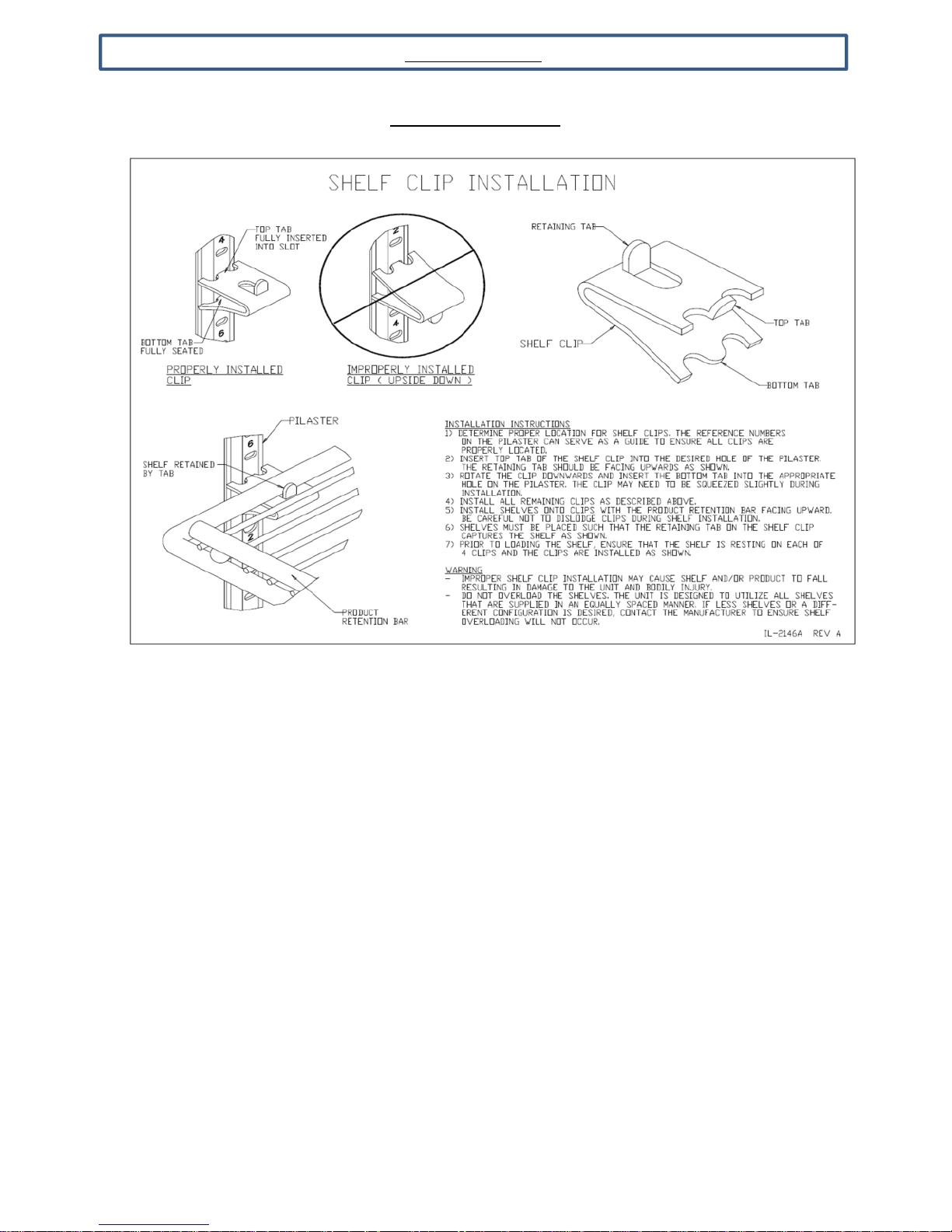
All cabinets with shelves are supplied with pilasters and shelf clip supports. Shelves are
easily installed by inserting the shelf support clips into the pilasters so that they fit
tightly.
Adjust the shelf so that the smaller fill wires run from front to rear and the shelf frame
wire rest the shelf on the clips.
809-114A Rev B 2017-03-30
8
Page 9
INSTALLATION
SHELVING ASSEMBLY
809-114A Rev B 2017-03-30
9
Page 10
INSTALLATION
2.6 Cabinet Cleaning
Warning: Cabinet MUST NOT SHARE A RECEPTACLE with another piece of equipment
WARNING: DO NOT clean with any product containing bleach or ammonia. Rinse
with clean water before drying with clean cloth.
Prior to use, the interior and exterior surfaces of the cabinet should be cleaned thoroughly with warm
water, mild detergent, and a soft cloth. Apply with a dampened cloth and wipe in the direction of the metal
grain. Then allow to air dry with the doors open. Only use a clean soft cloth. See detailed cleaning
instructions in the Preventative Maintenance section below.
2.7 Electrical supply
115 volt self-contained units are provided with a 15 or 20 amp power chord with plug that is shipped
coiled on top of the cabinet. The power cord is equipped with a three prong (grounding) plug which is to
be used in an appropriately rated and dedicated three prong (grounding) receptacle.
*NOTE: have a wall outlet checked by a qualified electrician for polarity and proper grounding
prior to plugging in the power cord.
For units not provided with a power cord, the electrical connection should be made by a qualified
electrician and in accordance with local electrical codes. The electrical requirements are located on the
rating (or data plate) located on the left hand side of the interior of the cabinet. Use of a dedicated circuit
with separate grounding wire is required.
2.8 Controller
The controls are designed for the refrigeration units to maintain a product temperature of 38 F and the
freezers to maintain a product temperature of 0 F. See section 3.1 for control display information.
2.9 Installation Checklist
After the cabinet has been installed, leveled, and cleaned as described above, refer to the following check
list:
Check for proper electrical hook-up.
Check that all clearances are in line with the aforementioned guidelines.
Check that cabinet is level.
* NOTE: Once the unit has been started and reaches proper storage temperatures, it may be
loaded with product. For proper energy efficiency and airflow we recommend a minimum1”
clearance between product and side walls, 4” clearance between product and ceiling, and 1”
clearance from the bottom of the unit.
10
809-114A Rev B 2017-03-30
Page 11
UNIT STARTUP
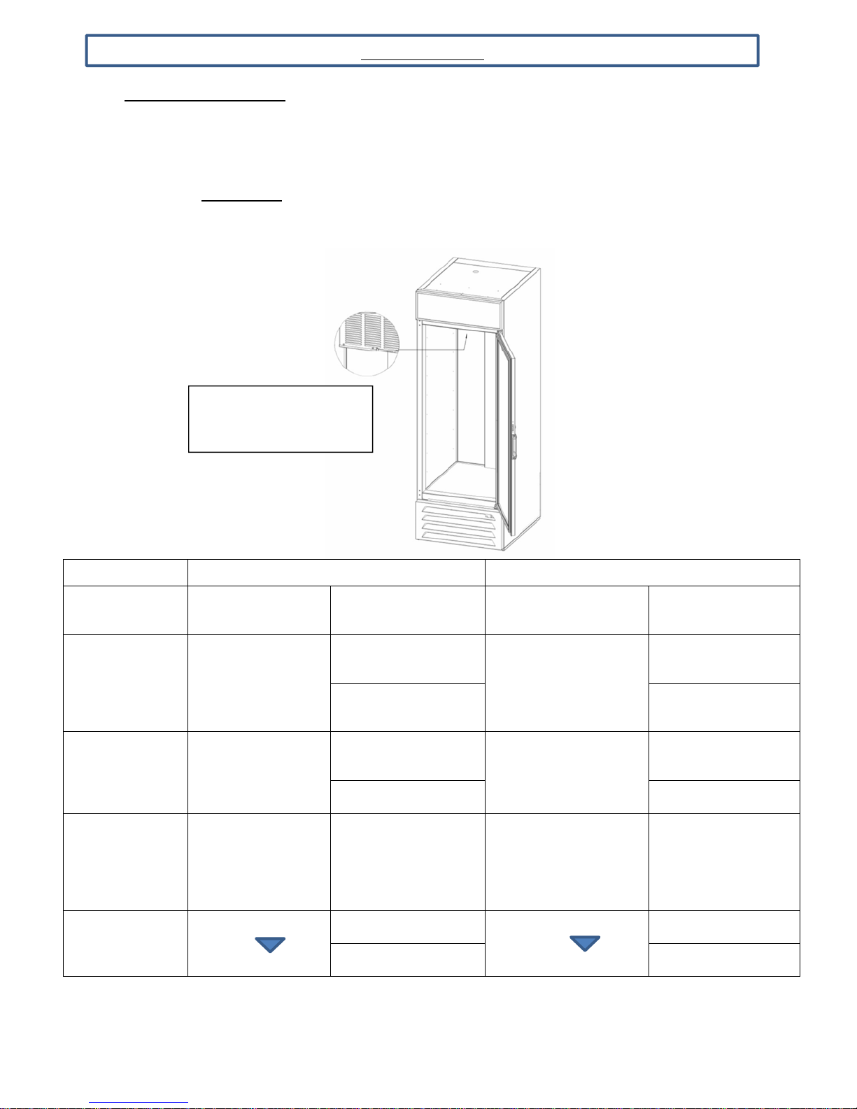
3.1 Sequence of Operations
THE LV, RI, RID, RB & FB MODELS OPERATIONS ARE CONTROLLED THROUGH THE
USE OF AN ELIWELL®NEW 974 CONTROLLER
3.1.1 Refrigerator
The refrigerator operates based on the air temperature measured by the probe located at the
return air.
PROBE IS LOCATED
BEHIND EVAPORATOR
COVER
COMPONENT OPERATION
Compressor turns
on when the air
COMPRESSOR
CONDENSER
FAN
EVAPORATOR
FAN
LIGHT
temperature at the
probe is above the
sum of the set point
and the dead band
The Condenser Fan
turns on when the
Compressor is
running
The Evaporator Fan
runs continuously.
When the unit is
plugged in, the
Evaporator Fan will
run.
The light will turn on
when the is
pressed
ON OFF
CONTROLLER
ACTION
The Compressor
Contact is energized
(nEW974 - Terminal
#4)
The Condenser Fan is
wired to the
Compressor Contact
(nEW974 - Terminal
#4)
The Evaporator Fan is
connected directly to
incoming power, not
through the controller.
The Light Contact is
energized
(nEW974 - Terminal
#3)
OPERATION
Compressor turns off
when the air
temperature at probe is
equal to or less than
the set point
The Condenser Fan
turns off when the
Compressor is not
running
The Evaporator Fan
runs continuously.
When the unit is
plugged in, The
Evaporator Fan will run.
The light will turn off
when the
is pressed
CONTROLLER
ACTION
The Compressor
Contact is de-
energized
(nEW974 - Terminal
#4)
The Condenser Fan
is wired to the
Compressor Contact
(nEW974 - Terminal
#4)
The Evaporator Fan
is connected directly
to incoming power,
not through the
controller.
The Light Contact is
de-energized
(nEW974 - Terminal
#3)
809-114A Rev B 2017-03-30
11
Page 12
UNIT STARTUP
Condition
Compressor
Condenser
Fan
Evaporator
Fan
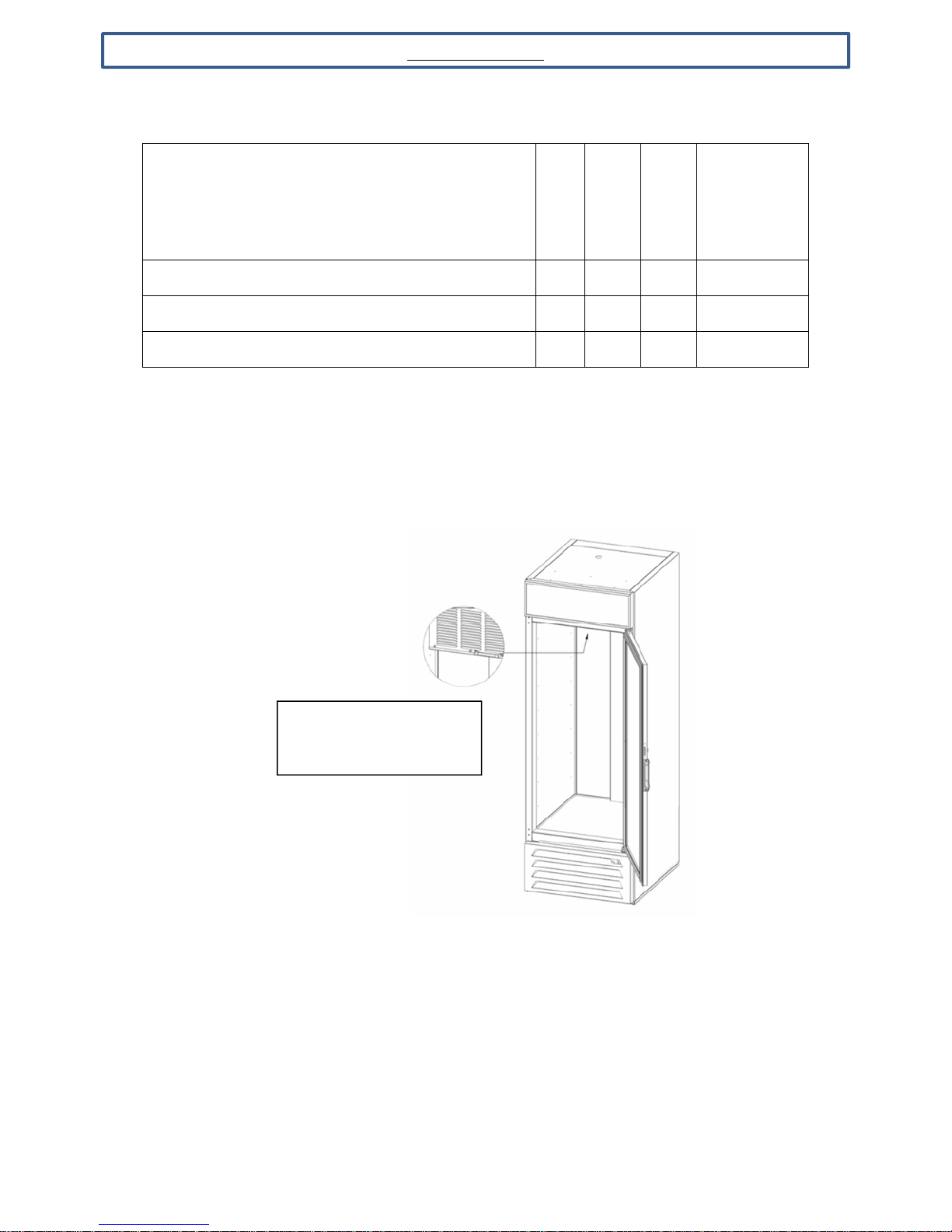
Cabinet Temp > Setpoint + Deadband ON ON ON ON or OFF
Cabinet Temperature <= Sepoint OFF OFF ON ON or OFF
Defrost OFF OFF ON ON or OFF
3.1.2 Freezer
The freezer operates based on the air temperature measured by the probe located at the return
air.
Lights
PROBE IS LOCATED
BEHIND EVAPORATOR
COVER
12
809-114A Rev B 2017-03-30
Page 13
UNIT START UP
ON OFF
The Condenser Fan is
(
nEW974
-
Terminal #4)
(
nEW
974-Terminal #4)
The
Evaporator Fan is
(
nEW974
-
Terminal #4)
(
nEW
974-Terminal #4)
The
Door/Face Heater
The
Door/Face Heater
The Light Contact is
(nEW
974-Terminal #
3)(
nEW
974-Terminal #
3
)
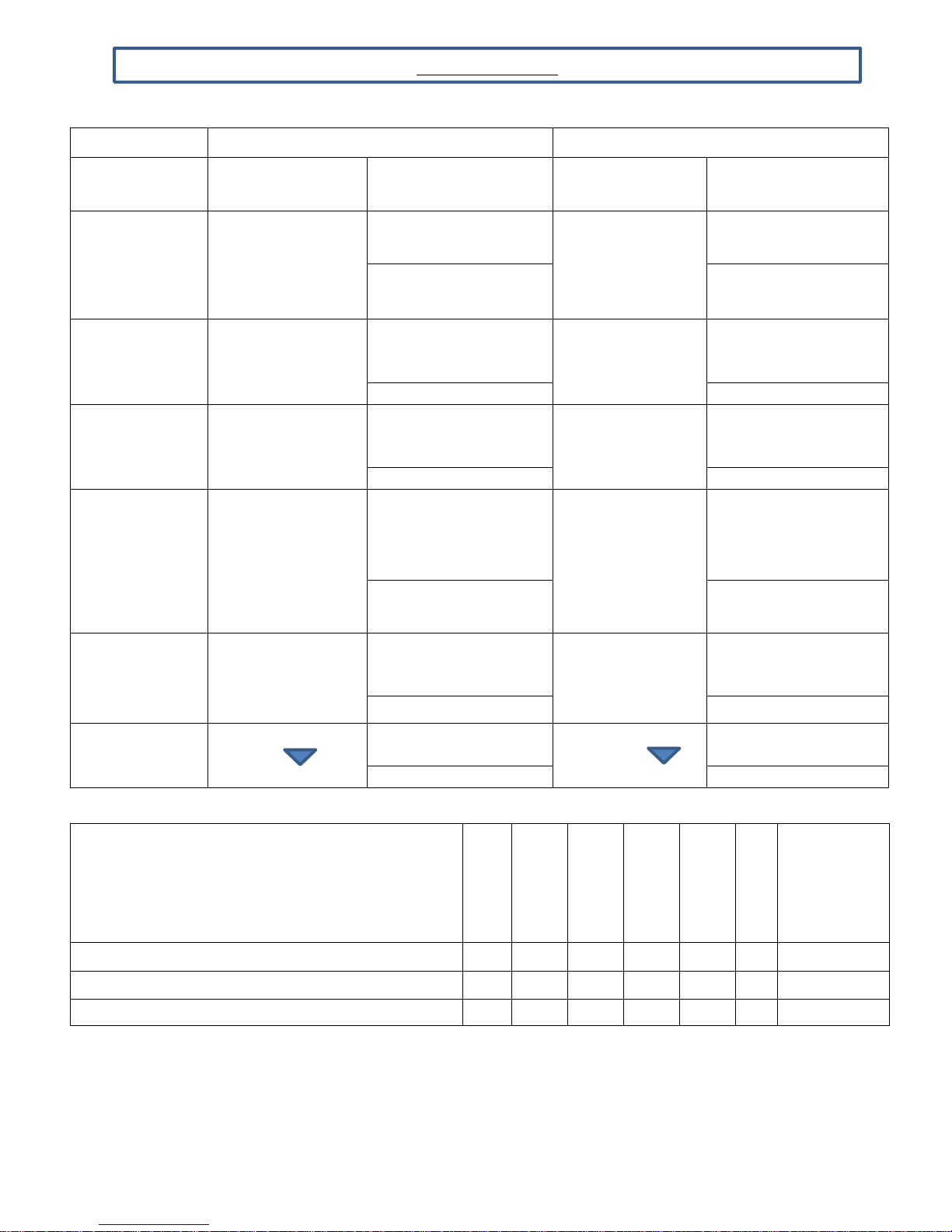
COMPONENT OPERATION
Compressor turns
on when the air
COMPRESSOR
CONDENSER
FAN
EVAPORATOR
FAN
DEFROST
HEATER
FACE/DOOR
HEATERS
LIGHT
temperature at the
probe is above the
sum of the set point
The Condenser Fan
turns on when the
Compressor is
running
The Evaporator Fan
turns on when the
Compressor is
running
The Defrost Heater
is on a timer; set at
4 to 6 equally
spaced defrost
periods each day
The Face & Door
Heaters turn on
when the
Compressor is
running
The light will turn on
when the is
pressed
CONTROLLER
CONTROLLER
OPERATION
ACTION
The Compressor
Contact is energized
(nEW974 - Terminal #4) (nEW974 - Terminal #4)
wired to the
Compressor Contact
wired to the
Compressor Contact
The Defrost Heater
Contact is energized
(nEW974 - Terminal #2) (nEW974 - Terminal #2)
are wired to the
Compressor Contact
(nEW974 - Terminal #4) (nEW974 - Terminal #4)
energized
Compressor turns
off when the air
temperature at
probe is equal to or
less than the set
point
The Condenser
Fan turns off when
the Compressor is
not running
The Evaporator
Fan turns off when
the Compressor is
not running
When either the
defrost is not
scheduled or the
temperature at
defrost probe has
reached the defrost
termination
temperature.
The Face & Door
Heaters turn off
when the
Compressor is not
running
The light will turn
off when the
is pressed
Contact is de-energized
Contact is de-energized
The Light Contact is de-
ACTION
The Compressor
The Condenser Fan is
wired to the
Compressor Contact
The Evaporator Fan is
wired to the
Compressor Contact
The Defrost Heater
are wired to the
Compressor Contact
energized
Condition
Cabinet Temp > Setpoint + Deadband ON ON ON OFF ON ON ON or OFF
Cabinet Temperature <= Sepoint OFF OFF OFF OFF OFF ON ON or OFF
Defrost OFF OFF OFF ON OFF ON ON or OFF
809-114A Rev B 2017-03-30
13
Compressor
Condenser
Fan
Evaporator
Fan
Defrost
Heater
Face/Door
Heater
Drain Heater
Lights
Page 14
UNIT STARTUP
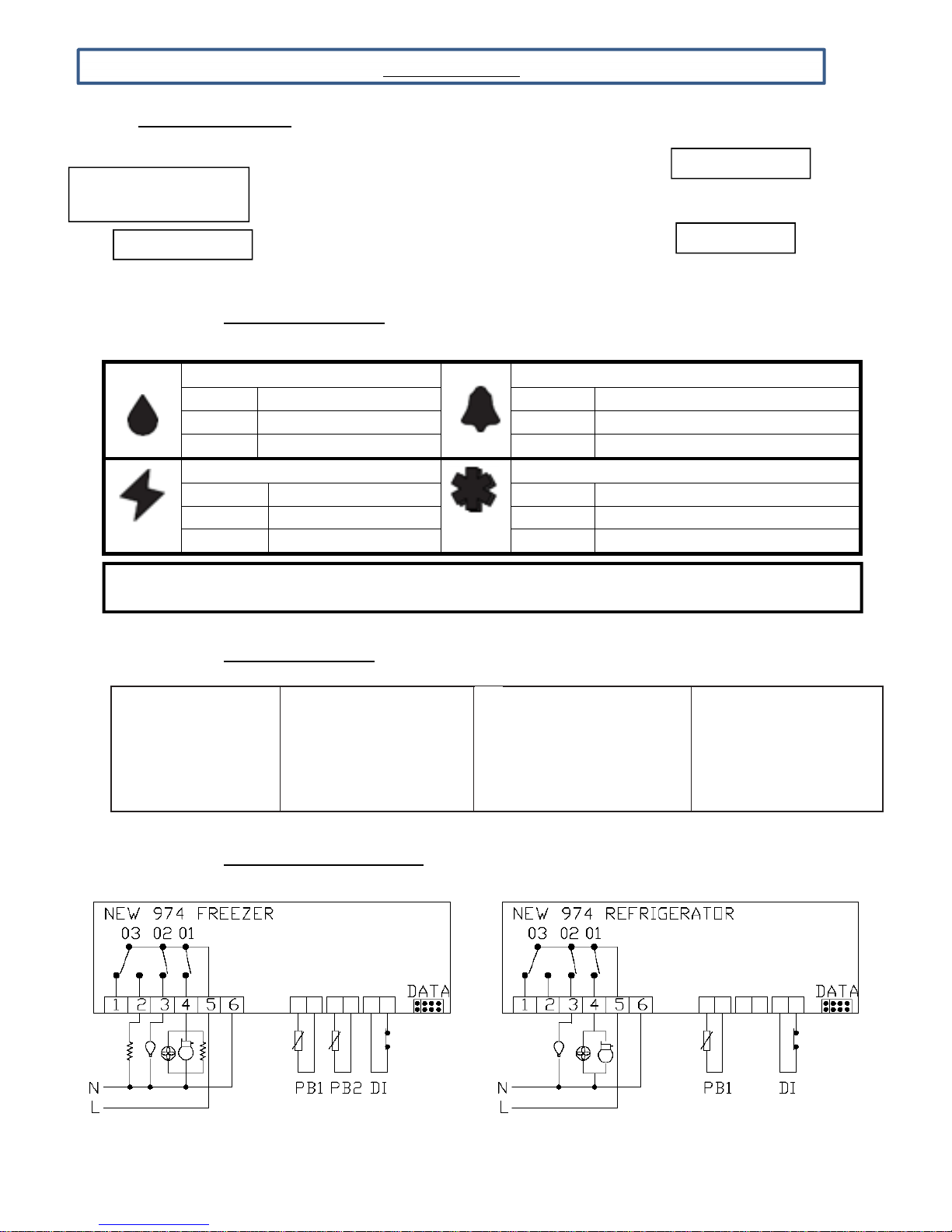
3.2 Electronic Controller
Defrost LED
STAND
-
BY (ESC)
SET (ENTER)
MANUAL DEFROST
LIGHT ON/OFF
(FREEZER)
3.2.1 Control Panel Display
On fixed: Automatic defrost active On fixed: ALARM Present
Flashing: Manual defrost active Flashing: ALARM Silenced
Off: Defrost is off Off: No Alarm
Aux LED Compressor LED
On fixed:
Off:
AUX output active
AUX output Off
Alarm LED
On fixed: Compressor active
Flashing: Delay, protection or activation blocked
Off: No Alarm
NOTE: When switched on, the instrument panel performs a lamp test and for a few seconds, the display and LEDs flash to verify
their condition and proper operation.
3.2.2 Keyboard Functions
UP
Press and release
•
Scrollsthemenuitems
•
Increases the values
DOWN
Press and release
•
Scrollsthemenuitems
•
Decreases the values
STAND-BY (ESC)
Press and release
•
Returnsuponelevel with respect to
the
current menu
•
Confirms the parameter value
SET (ENTER)
Press and release
•
Accesses the machine status menu
and
displaysanyalarms(if present)
3.2.3 Control Panel Connections
809-114A Rev B 2017-03-30
14
Page 15

UNIT START UP
3.2.4 Changing the Setpoint
Press and release the button to enter the machine status menu.
The screen will display SP
Press and release the button again to see the current set point value (see image
below).
To adjust to a different value press and release the and buttons.
Press and release the button to accept the value.
Press and release the button to exit out of the machine status menu.
809-114A Rev B 2017-03-30
15
Page 16

UNIT START UP
3.2.5 Viewing the current Probe Temperature
Press and release the button to enter the machine status menu.
The screen will display SP
Use the and buttons to change the display to S1
Press and release the button to view the current sensor value.
16
809-114A Rev B 2017-03-30
Page 17
UNIT START UP
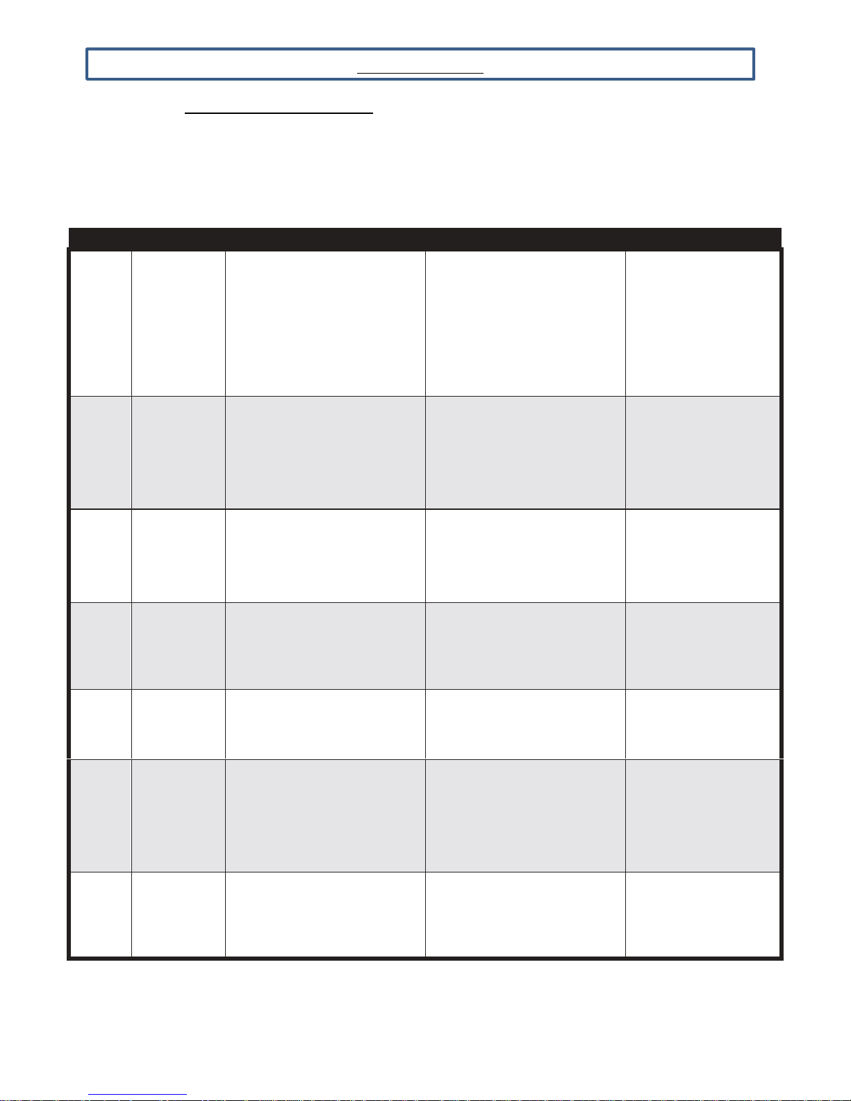
3.2.6 Electronic Controller Alarms
Label
Descripti
Cause
Effects
Troubleshooting
alarm on D.I.
The alarm condition is always signaled by the alarm icon . To turn off the relative icon will continue
flashing.
NOTE: If alarm exclusion times are in progress (AL folder of the parameter table), the alarm is not
signaled.
• Display of label E1
• Fixed alarm icon
E1
Pb1probe
error (cell)
• Reading of values outside the
operating range
• Probe is inoperable /short
circuit/open
• Disabling of the max/min
alarm regulator
• Compressor operation
based on the
• Check the type of
probe (NTC)
• Check the probe wiring
• Replace the probe
parameters P0 and P1
• Display of label E2
• Fixed alarm icon
• Defrosting ends due to time
out (d3)
• The evaporator fans are
• Check the type of
probe (NTC)
• Check the probe wiring
• Replace the probe
E2
Pb2 probe
error
(defrosting)
• Reading of values outside the
operating range
• Probe is inoperable/short
circuit/open
disabled
Ht
Lt
EA
ES
OP
HIGH alarm
Pb1
temperature
LOW alarm
Pb1
temperature
External
alarm
Energy
Saving +
reduced set
point
Alarm
Door
open
Value read by Pb1 > A2 after
time equal to A7.
(see ‘TEMP. ALARMS
MAX/MIN’)
Value read by Pb1 < A3 after
time equal to A7.
(see ‘TEMP. ALARMS
MAX/MIN’)
Activation of the digital
input (i3 = 6)
• Activation of the digital
input (i3 = 1,5, 8)
• Activation from key if H1...3=2
(see paragraph Key
Functions)
Activation of the digital input
(i3 = 4) (for a time greater than
r1)
• Recording of label Ht in the AL
folder
• Fixed alarm icon
• No effect on regulation
• Recording of label Lt in the AL
folder
• Fixed alarm icon
• No effect on regulation
• Recording of label EA in the
ALfolder
• Fixed alarm icon
• Display of label ES
alternating with the
setpoint value
• Regulation to the value set at
C5 parameter.
• Recording of label OP in the
ALfolder
• Fixed alarm icon
Wait for the value ready
by Pb1 to return below
A2-A1
Wait for the value ready
by Pb1 to return above
A3+A1.
Check and remove
the external cause
that caused the
• D.I. Open
• Press associated with
the functionkey
• Close the door
• Delayed function
defined by A6
809-114A Rev B 2017-03-30
17
Page 18
UNIT START UP
3.2.7 How to View Alarms
Press and release the button to enter the machine status menu.
The screen will display SP
Use the and buttons to change the display to AL
Press and release the button to view the alarm(s)
If more than one alarm is present, use the and buttons to scroll through them.
18
809-114A Rev B 2017-03-30
Page 19

UNIT START UP
3.2.8 How to Enter the StandBy Mode
The Stand By Mode is used to remove power from the condensing unit (Compressor &
Condensing Fan) so the coil can be cleaned or the unit defrosted without having to disconnect the power
from the unit)
In Refrigerator models the Evaporator Fan will continue to run
In Freezer models, power is disconnected from the Evaporator Fan, so it does not run.
Press and release the button for 5 seconds until St is displayed
Press and hold the button to confirm. OF will be displayed, the unit is now in
Standby mode.
3.2.9 How to Exit the StandBy Mode
Press and release the button for 5 seconds until St is displayed
Press and hold the button to confirm. The cabinet temperature will be displayed, the
unit is now in Normal Operation
809-114A Rev B 2017-03-30
19
Page 20
PREVENTA
TIVE MAINTENANCE
4.1 Daily, Exterior
1 - Clean the surface with a sponge and dilute mild detergent. Use a non-abrasive cleaner that
does NOT contain chlorine.
2 - Rinse with clean water before drying with clean soft cloth.
3 - Polish with a soft cloth, wiping with the grain of the metal.
4 - Once a week wipe with a film cutting agent or stainless steel polish to maintain finish.
4.2 Weekly, Interior
1 - Remove all food, food related items, and shelves.
2 - Disconnect power to the cabinet at the main power supply circuit breaker
3 - Remove loose food particles from interior floors, walls, and ceiling
4 - Scrub all interior surfaces and door gaskets with a warm (100-120F) detergent solution
and a soft nylon bristle brush
5 - Rinse with clean water and allow to air dry
6 - Re-install the shelves
7 - Restore power to the cabinet by resetting main power supply circuit breaker
8 - Return food to the cabinet when temperature indicator displays safe food temperature
4.3 Monthly, Condenser
The condenser coil is located right behind the front grille on top of the cabinet. It should be
inspected once a month and cleaned as required. Vacuum clean all surfaces of the condenser.
Make sure no fins are bent or damaged in the process. If there are bent fins, carefully straighten
them so that air can flow through the coils. Failure to keep the condenser coil clean will lead to
poor performance, excessive power consumption and compressor failure and may result in loss
of property. Failure to keep the condenser coil clean may void the limited warranty.
4.4 Periodic, Gaskets
1 Visually inspect the door gaskets for a tight seal on all four sides. Inspect for any type of
damage such as rips, tears, stiffness, or cracks.
2 If any such condition exists, the magnet will not seal and the gasket will need replaced.
3 Cleaning the gasket requires the use of mild dish detergent and warm water.
4 Next, thoroughly rinse and dry the gasket.
809-114A Rev B 2017-03-30
20
Page 21
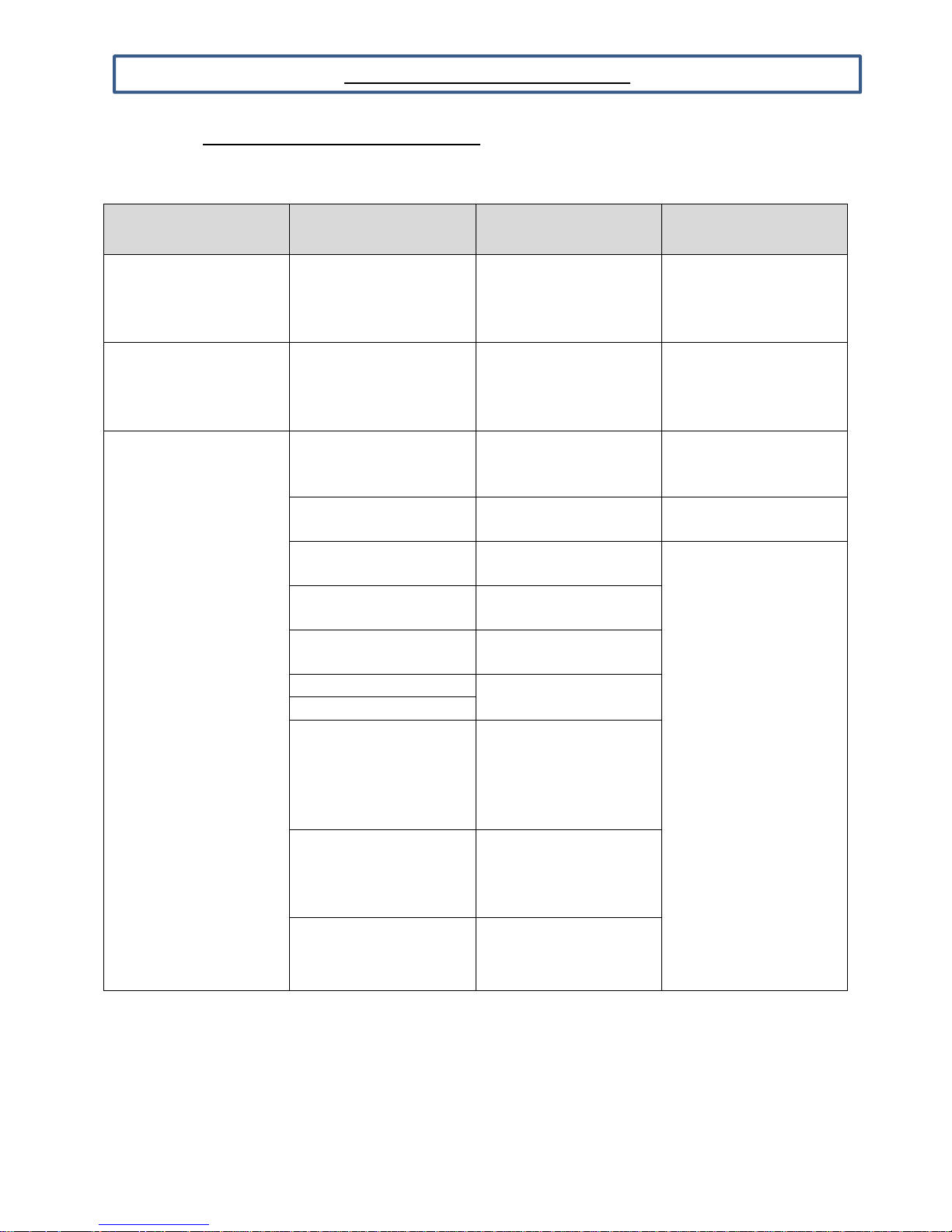
PREVENTATIVE MAINTENANCE
4.5 Effective Methods for Cleaning Stainless Steel
Type of Cleaning
Routine Cleaning
Smears and Fingerprints
Stubborn Spots and Stains,
Baked-On Splatter, and
Other Light Discolorations
Cleaning
Agent
Soap or ammonia, or
detergent and water.
Arcal 20, Lac-O-NU, Lumin
Wash O'Cedar Cream
Polish, Stainless Shine.
Allchem Concentrated
Cleaner.
Samae, Twinkle or Cameo
Copper Cleaner.
Grade FFF Italian pumice,
whit- ing, or talc.
Liquid NuSteal.
Paste NuSteal or DuBois
Temp.
Copper's Stainless Steel
Cleaner Revere Stainless
Household cleansers, such
as Old Dutch, Lighthouse,
Sun- brite, Wyandotte,
Bab-O, Gold Dust, Sapolio,
Bon Ami, Ajax, or Comet.
Grade F Italian pumice,
Steel Bright, Lumin
Cleaner, Zud, Restoro, Sta-
Clean, or Highlite.
Penny-Brite or Copper-
Brite.
Method of
Application
Sponge with cloth, then
rinse with clear water and
wipe dry
Rub with cloth as directed
on the package.
Apply with damp sponge
or cloth
Rub with damp cloth.
Rub with damp cloth.
Rub with dry cloth. Use
small amount of cleaner.
Rub with dry cloth using a
small amount of cleaner.
Apply with damp sponge
or cloth.
Rub with a damp cloth.
May contain chlorine
bleaches. Rinse
thoroughly after use.
Rub with a damp cloth.
Rub with a dry cloth
using a small amount of
cleaner.
Effective
Finish
Satisfactory for use on all
finishes.
Satisfactory for use on all
finishes. Provides barrier
film to minimize prints.
Satisfactory for use on all
finishes.
Satisfactory for use on all
finishes if rubbing is light.
Use in direction of polish
lines on No. 4 (polished)
finish. May scratch No. 2
(mill) and Nos. 7 and 8
(polished) finishes.
809-114A Rev B 2017-03-30
21
Page 22
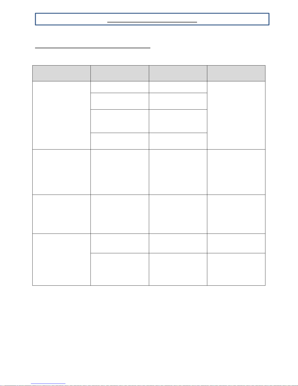
PREVENTATIVE MAINTENANCE
4.5 Effective Methods for Cleaning Stainless Steel
Type
of Cleaning
Heat Tint or Heavy
Discoloration
Burnt-On Foods and
grease
Fatty Acids, Milkstone
(where swabbing or
rubbing is not practical)
Tenacious Deposits,
Rusty Discolorations,
Industrial Atmospheric
Stains
Hard Water Spots and
Scale
Cleaning
Agent
Penny-Brite or Copper-
Brite.
Past NuSteel, DuBois
Temp, or Tarnite.
Revere Stainless Steel
Cleaner. Allen Polish,
Steel Bright, Wyan- dotte,
Bab-O, or Zud.
Revere Stainless Steel
Cleaner.
Easy-Off, De-Grease-It,
4 to 6% hot solution of
such agents as
trisodium phosphate or
sodium tripolyphosphate
or 5 to 15% caustic
soda solution.
Oakite No. 33, Dilac
Texo 12, Texo N. Y.,
Flash-Klenz, Caddy
Cleaner, Turco Scale
4368 or Permag 57.
Vinegar.
5% oxalic acid, 5%
sulfamic acid, 5 to 10%
phosphoric acid, or
Dilac, Oakite No. 33,
Texo 12, Texo N. Y.
Method of
Application
Rub with a dry cloth.
Rub with a dry cloth or
stainless steel wool.
Rub with a damp cloth.
Apply with damp sponge or
cloth.
Apply generous coating.
Allow to stand for 10-15
minutes. Rinse.
Repeated application
may be necessary.
Swab and soak with
clean cloth. Let stand 15
minutes or more
according to directions
on package, then rinse
and dry.
Swab or wipe with cloth.
Rinse with water and
dry.
Swab or soak with cloth.
Let stand 10-15
minutes. Always follow
with neutralizer rinse,
and dry.
Effective
Finish
Use in direction of
polish lines on No. 4
(polished) finish. May
scratch No. 2 (mill) and
Nos. 7 and 8 (polished)
finishes.
Excellent removal,
satisfactory for use on
all finishes.
Satisfactory for use on
all finishes.
Satisfactory for all
finishes.
Satisfactory for all
finishes. Effective on
tenacious deposits or
where scale has built
up.
809-114A Rev B 2017-03-30
22
Page 23
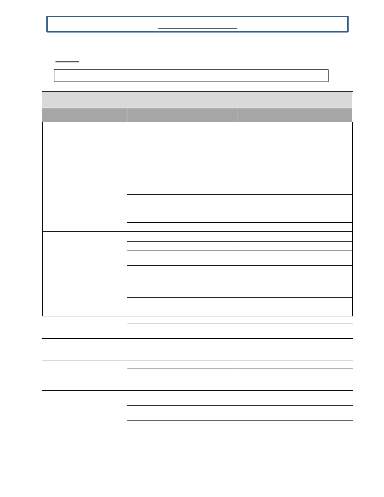
TROUBLE SHOOTING
WARNING:
ALL
SERVICING MUST COMPLY WITH STATE AND FEDERAL
EGULATIONS
5.1 General
SERVICE AND REFRIGERATION SYSTEM CHART ANALYSIS
Malfunction Possible Cause Solution
Compressor will not start –
no hum
Compressor starts and runs
but unit does not begin to
cool on initial start-up (MT
Bare Tube Condenser
Models only)
Unit runs OK, but short
cycles
Unit operates long or
continuously
Start capacitor open,
shorted or blown.
Run capacitor open,
shorted or blown.
Relay defective or burned
out.
Space temperature too
high.
Cooler freezing beverage Temperature control Reset control
Unit noisy
Line cord not plugged in Plug cord in
Ambient is below 60°F
Overload protector.
Cold control. Differential set too close
Overcharge. Reduce refrigerant charge.
Air in system. Recover and recharge.
Undercharge. Fix leak and recharge with refrigerant.
Dirty condenser Clean condenser
Shortage of refrigerant. Fix leak, add charge, correct charge
Temp control contacts stuck or
frozen
Evaporator coil iced. Defrost
Restriction in refrigeration system. Determine location and remove.
Relay contacts not opening properly. Replace relay
Low voltage to unit. Determine reason and correct.
Improper relay. Replace.
Improper capacitor. Determine correct size and replace.
Excessively high line voltage (110%
of rated max).
Line voltage too high or too low. Determine reason and replace.
Relay being influenced by loose
vibrating mounting.
Control setting too high. Reset control.
Overcharged with refrigerant
Inadequate air circulation. Improve air movement
Loose parts or mountings Find and tighten
Tubing rattle Reform to be free of contact
Bent fan blade causing vibration Replace blade
Fan motor bearings worn Replace motor
Warm unit to above 60°F prior to initial
start-up.
Check wiring diagram for correct
wiring
Replace Temp control
Determine reason and correct.
Remount rigidly.
Recover refrigerant and recharge with
Proper charge specified on data plate
809-114A Rev B 2017-03-30
23
Page 24
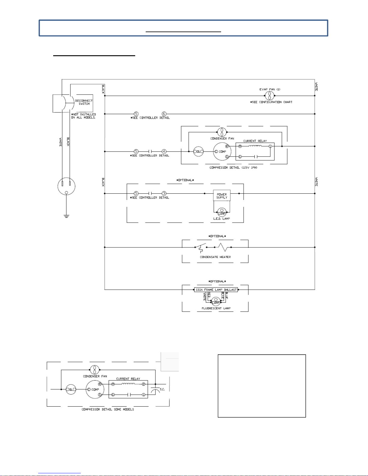
5.2 Refrigerator Ladder Diagram
LEGEND
TROUBLE SHOOTING
SPE Models Only
RC – Run Capacitor
SC – Start Capacitor
OL – Overload
- Eliwell Controller Terminal
- Connection Point
ICR – Control Relay
809-114A Rev B 2017-03-30
24
Page 25
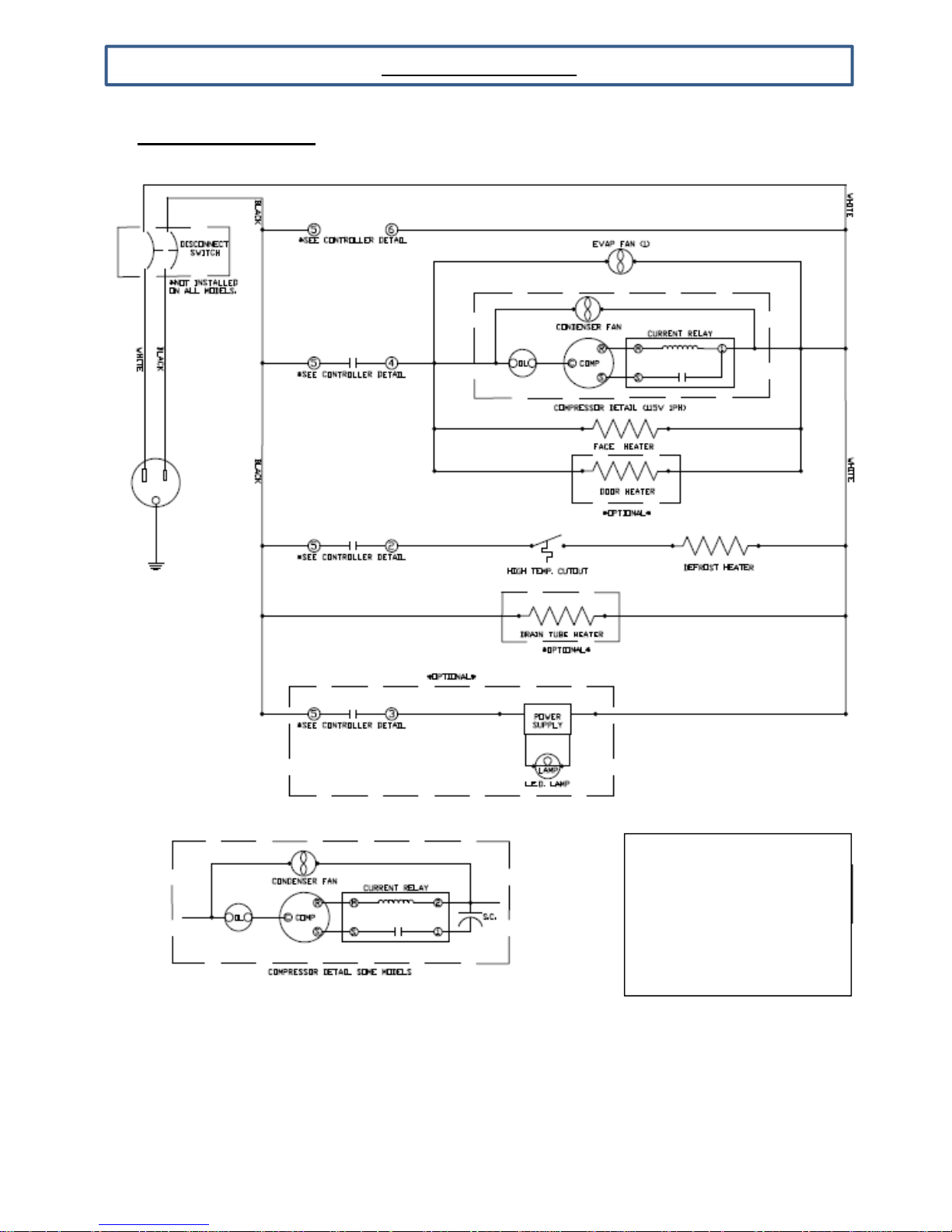
5.3 Freezer Ladder Diagram
LEGEND
TROUBLE SHOOTING
809-114A Rev B 2017-03-30
RC – Run Capacitor
SC – Start Capacitor
OL – Overload
- Eliwell Controller Terminal
- Connection Point
ICR – Control Relay
25
Page 26
APPENDIX
SERVICE RECORD
809-114A Rev B 2017-03-30
26
 Loading...