

Page 1

SERVICE &
INSTALLATION
MANUAL
ICE CREAM
DIPPING
CABINETS
R-404A Refrigerant
1/2003 51-1468-01
CARRIER COMMERCIAL REFRIGERATION, INC.
Providing BEVERAGE-AIR • FRIGIDAIRE • KELVINATOR • UNIVERSAL NOLIN Products/Services
Page 2

If additional information is necessary, call the factory.
Our toll free number is 1-800-684-1199.Technical
assistance engineers are willing to assist you in any way
possible. Office hours are from 8:00a.m. to 5:30 p.m.,
Eastern Standard Time.
Important information is contained in this manual which should
be retained in a convenient location for future reference.
MODEL DESIGNATION INFORMATION
115V, 60HZ
PART # MODEL # DATA PLATE
52-1961-35 BRT-68 BRT68
52-2077-02 BRT68P BRT68
52-2077-04 BRT68W BRT68
52-1961-36 BRT90 BRT90
52-2077-03 BRT90P BRT90
52-2077-05 BRT90W BRT90
EXPORT 220V, 50HZ
PART # MODEL # DATA PLATE
52-1961-31 EBRT-68 EBRT68
52-1961-41 EBRT68P EBRT68
52-1961-32 EBRT90 EBRT90
52-1961-42 EBRT90P EBRT90
EXPORT 220V, 60HZ
PART # MODEL # DATA PLATE
52-1961-33 KBRT-68 KBRT68
52-1961-34 KBRT90 KBRT90
Manual effective for models produced January, 2003. Starting ser ial number 6527372.
Page 3
SECTION I
Introduction
Page 4

blank
Page 5
Dipping Cabinets - Introduction
These Dipping Cabinets are designed to merchandise ice
cream or yogurt-type products.Dipping cabinets are
produced in three sizes: 8,12,and 16 facings of ice cream
containers.The cabinet systems contain CFC free refr igerant,
metered into the system by a capillary tube.The evaporator
is a cold wall which has the refrigerant lines strapped to the
inner liner of the cabinet.The condenser is a bare tube
mounted on a pullout machinery compartment tray for ease
of servicing. All electrical controls are easily accessible for
repair.The temperature within the cabinet is controlled
thermostatically, allowing for maintenance of correct dipping
temperatures.
Mechanical equipment may require repair at times.This
manual presents information that is helpful in maintaining,
diagnosing,and repairing these cabinets .
The high level of quality built into these units will allow for
many years of trouble-free operation.
INTRODUCTION 3
Page 6

TABLE OF CONTENTS
4TABLE OF CONTENTS
Due to Frigidaire’s policy of continuous quality improvement, specifications are subject to change without notice.
INTRODUCTION
Introduction ........................................................................ 3
Table of Contents ................................................................4
Cabinet Specifications / Dimensional Data: BRT-68 ............ 5
Cabinet Specifications / Dimensional Data: BRT-90 ............ 6
Handling & Installation ...................................................... 7
PRINCIPLES OF OPERATION
General Information - Refrigeration Systems.................... 11
BRT-68 Electrical & Refrigeration Information .................. 13
BRT-90 Electrical & Refrigeration Information .................. 14
EBRT-68 & KBRT-68 Electrical &Refrigeration Info ........ 15
EBRT-90 & KBRT-90 Electrical &Refrigeration Info ........ 16
BRT-68 & BRT-90 Wiring Diagram .................................. 17
EBRT/KBRT-68 & 90 Wiring Diagram .............................. 18
MAINTENANCE & REPAIR
Pre-Service Check List ...................................................... 21
General Maintenance Information .................................... 22
Compressor Installation / Diagnostics .............................. 24
Cleaning & Maintenance .................................................. 26
Cleaning the Lid ................................................................ 27
Lid Seal Replacement ...................................................... 28
Lid Gasket Replacement .................................................. 29
Lid Pivot Bushing Assembly Replacement ...................... 30
Center & End Pivot Rod Replacement .............................. 31
Fluorescent Lamp Holder/Light Starter Socket Replac. .... 32
Fluorescent Bulb & Starter Replacement .......................... 33
Thermostat Replacement .................................................. 34
Master Power Supply Switch / Light Switch Removal ...... 35
Condenser Fan Motor Replacement .................................. 36
Ballast Replacement ........................................................ 37
Metering Device / Heat Exchanger Replacement .............. 38
Cabinet Troubleshooting Guide ........................................ 39
Compressor Troubleshooting Guide ................................ 42
Fluorescent Lamp Troubleshooting Guide ........................ 45
PARTS LISTS
Cabinet Parts .................................................................. 48
Lamp Assembly Parts ...................................................... 50
Condensing Unit Parts ...................................................... 52
Electrical Parts .................................................................. 54
Lid Parts .......................................................................... 56
Page 7
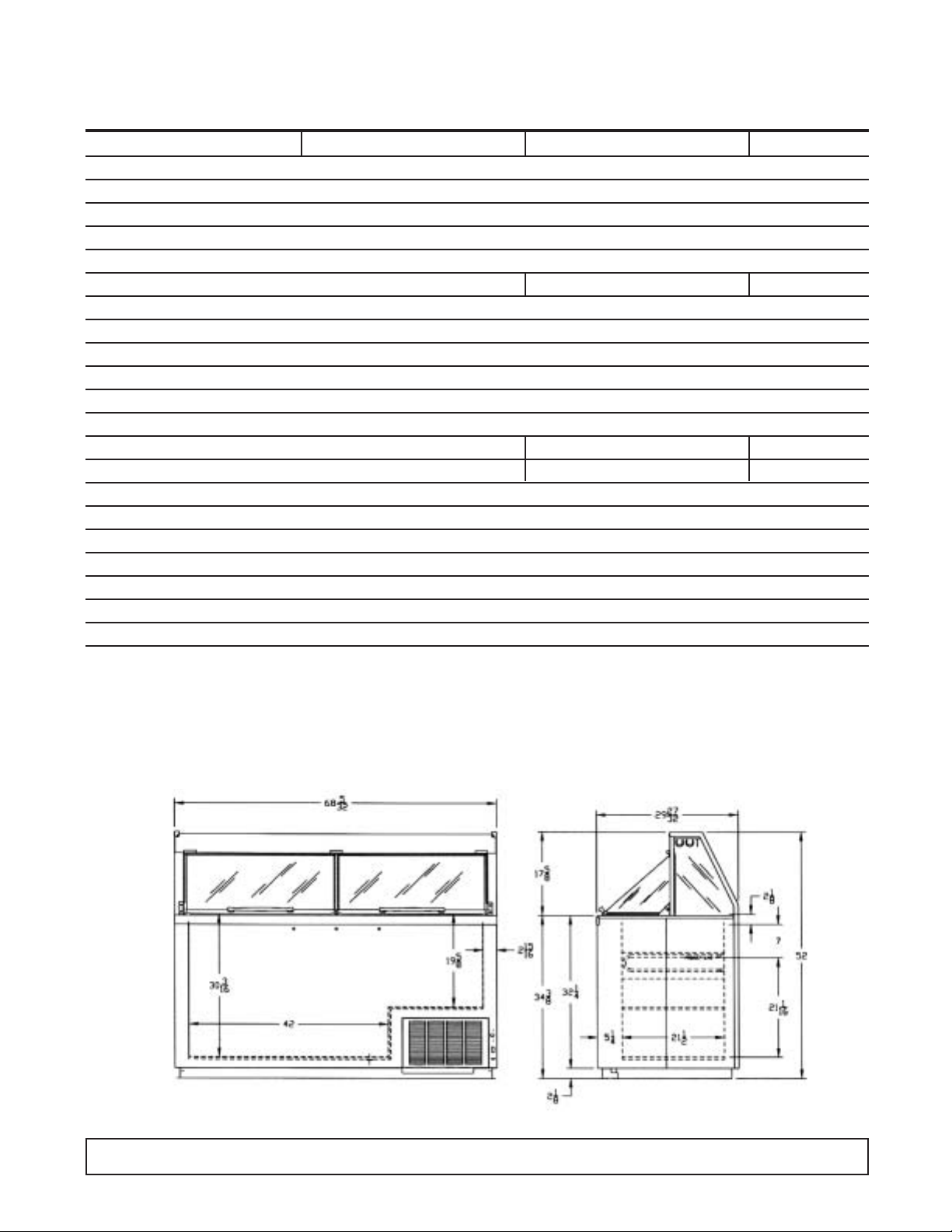
INTRODUCTION 5
CABINET SPECIFICATIONS
BRT68 EBRT68 KBRT68
Temp. Range +10°F to -8°F
Capacity 19.1 Cu. Ft.
Capacity (3 Gal. Tubs) 20
Facings (3 Gal. Tubs) 12
Storage (3 Gal. Tubs) 8
Compressor Size 1/3 Hp. 3/4 Hp. 3/4 Hp.
Shipping Weight (App.) 644 lbs.
Condenser Type Bare Tube
Evaporator Type Cold Wall - Refrigerated Cross Bars
Refrigerant R-404A
Refrigerant Control Capillary Tube
Defrost System Manual
Rated Amps 8.0 4.1 4.1
Electrical Specs. 115V, 60 Hz., 1 Ph. 220V, 50 Hz., 1Ph 220V, 60 Hz., 1 Ph.
Power Cord No. 16AWG
NSF Listing NSF1
Canopy Construction S.S. Top with Glass Ends Straight or Curved Front Glass
Lids (Plexiglass) 2 Lids
Interior Finish White Baked Enamel on Galvanized Steel
Exterior Finish White Baked Enamel
Lighting Two 40 Watt Bulbs
DIMENSIONAL DATA
REAR VIEW END VIEW
Page 8

6 INTRODUCTION
CABINET SPECIFICATIONS
BRT90 EBRT90 KBRT90
Temp. Range +10°F to -8°F
Capacity 24.4 Cu. Ft.
Capacity (3 Gal. Tubs) 28
Facings (3 Gal. Tubs) 16
Storage (3 Gal. Tubs) 12
Compressor Size 1/3 Hp. 3/4 Hp. 3/4 Hp.
Shipping Weight (App.) 754 lbs.
Condenser Type Bare Tube
Evaporator Type Cold Wall - Refrigerated Cross Bars
Refrigerant R-404A
Refrigerant Control Capillary Tube
Defrost System Manual
Rated Amps 8.0 4.1 4.1
Electrical Specs. 115V, 60 Hz., 1 Ph. 220V, 50 Hz., 1Ph 220V, 60 Hz., 1 Ph.
Power Cord No. 16AWG
NSF Listing NSF1
Canopy Construction S.S. Top with Glass Ends Straight or Curved Front Glass
Lids (Plexiglass) 2 Lids
Interior Finish White Baked Enamel on Galvanized Steel
Exterior Finish White Baked Enamel
Lighting Two 40 Watt Bulbs
DIMENSIONAL DATA
REAR VIEW END VIEW
Page 9

HANDLING & INSTALLATION-Illuminated Dipping Cabinets
INTRODUCTION 7
FREIGHT DAMAGES AND SHOR TAGES
IMPORTANT
The cabinet was inspected and packaged at the
factory, and should have arrived in excellent
condition. The transportation company or other
parties involved in the shipment are responsible for
loss and/or “damage.” Always make an inspection
before and after uncrating, pref erab ly at the point of
unloading by the transportation company.
INSPECTING FOR DAMAGES
Note:
Always use care when removing shipping tape,
blocks, pads, hardware or other material. Contact
your dealer or distributor if technical assistance
is required.
Check the cartons or containers. If these are damaged
in any way, open them and inspect the contents in the
driver’s presence. If damage is detected, do the
following:
1. Have the driver note the nature and extent of the
damage on the freight bill.
2. Notify the transportation company’s office to request
an inspection. Carrier claim policies usually require
inspections to be made within 15 days of delivery.
3. If damage is noticed, file a claim with the
transportation company.
FILING A CLAIM
File a claim for loss at once with the transportation
company for:
A. A cash adjustment B. Repairs C. Replacement
When filing your claim, retain all packaging materials
and receipts.
HANDLING THE CABINET
Note:
The refrigeration system of the cabinet is designed
to operate with the cabinet located on a flat surface.
Do not tilt the cabinet more than 30° to any side. If
the cabinet must be tilted on an angle for handling or
moving purposes, allow it to sit in an upright position
20 to 30 minutes prior to operating.
CHOOSE A LOCATION
This model cabinet should be situated to allow proper air
circulation. The cabinet must be installed on sturdy, level
floor and positioned so that it can be plugged into a
properly grounded three-prong electrical wall outlet. The
electrical outlet should not be controlled by a wall switch
which might be turned off accidentally.
UNCRATING THE CABINET
The cabinet should be moved as close as possible to
the operating location before removing the skid. Be
sure to follow the steps in the “INSPECTING FOR
DAMAGES” instructions.
INSTALLING THE CABINET
Whenever possible leave the crate skid on the cabinet
until it is moved close to the final position. When it is
necessary to move the cabinet through a doorway, it
may be necessary to remove the crate skid.
Run the cabinet down to storage temperature before
adding product.
CAUTION
A. Do not locate cabinet where sunlight or drafts from
fans, air conditioners or open doors can affect product
temperature.
B. Run cabinet before building in or attaching panels or
accessories.
C. Employee side access panel must be kept clear for
adjustments and service.
D. Cabinet must be installed on the finished floor to
assure rear raceway cover and condensing unit
(employee side) can be pulled or removed for service.
DO NOT seal in with cover molding or caulking in the
area where condensing unit pulls out.
E. Do not use extension cords to power this equipment.
Run any necessary electrical, water supply and drain
lines before setting the cabinet in position. Shim under
the cabinet as necessary to level it. N.S.F. approval
requires sealing the cabinet to the floor. This can be
done by applying a bead of mastic sealer between the
cabinet bottom flange and the floor.
Should several cabinets be set up in a row, space is
provided in the rear toe space for routing electrical and
plumbing lines.Access to this space requires removing
screws and the metal cover which runs the length of the
cabinet.
Rivnuts are provided on the operator's side for
mounting dipperwell and other accessories.
CABINET START-UP
Once the cabinet has been located in its permanent
location and the proper power and grounding have
been provided, the following items must be checked or
completed:
A. Cut and remove the compressor hold-down band (if
applicable) so the compressor “floats” freely.
Page 10
B. Check for traces of oil on the compressor pan which
could mean a broken or leaking refrigeration line.
UNDER NO CIRCUMSTANCE SHOULD THE
COMPRESSOR BE STARTED WHEN OIL IS
PRESENT UNTIL INSPECTED BY A SERVICE
TECHNICIAN.
C. INSPECT THE FACTORY WIRING FOR TERMINALS
THAT MIGHT HAVE VIBRATED LOOSE IN
SHIPPING. TIGHTEN ALL SCREW TYPE
TERMINALS.
D. Check the refrigeration lines to see that they are
“free” and no damage was done during shipping.
E. Check fan blade for free operation.
F. Turn on the main po wer s witch.Once the compressor
starts, the voltage should be checked at the
compressor terminals to determine if there is proper
voltage to the compressor. The voltage should not
exceed the 10% above or below the rated
compressor voltage.
EXAMPLE: If the voltage reads 115 volts with no load
and it drops below 103 volts when the compressor
starts, it may indicate that the supply wiring is too small
or that the wire run is too long.
G. Listen for any unusual noise such as lines vibrating,
etc. Correct the problem by tightening screws,
slightly bending tubing, etc.
H.The temperature control thermostat which is located
in the rear post is factory set for average conditions.
A customer adjustment requires a coin or
screwdriver to turn the slotted shaft.A numbered dial
makes it easy to keep track of adjustments. #1 is
warmest setting and #7 is coldest setting. An “OFF”
position is provided for your convenience in
defrosting the cabinet.
I. Allow the cabinet to pull down and cycle prior to
loading with product (Approx. 24 hours).
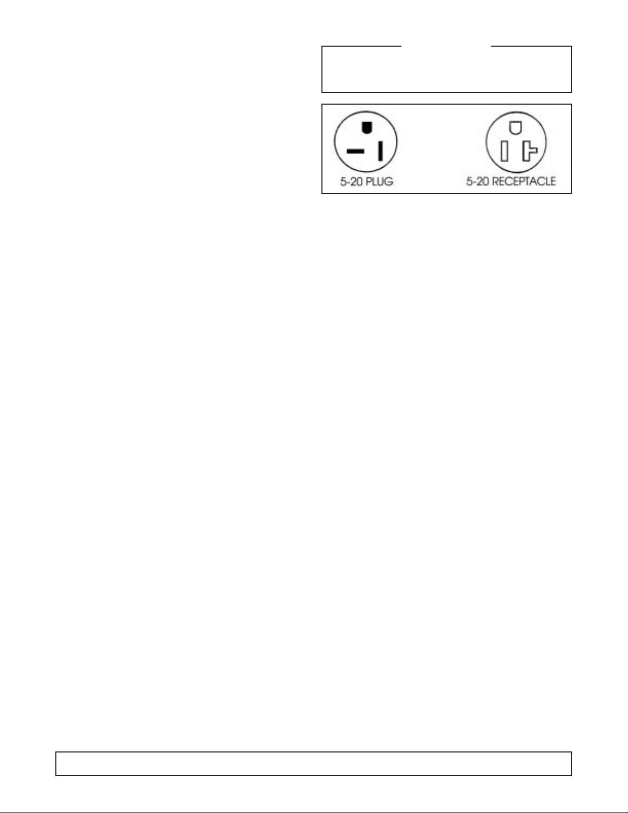
GROUNDING INSTRUCTIONS
This appliance is equipped with a three-prong
(grounding) plug for your protection against shock
hazards.The appliance should be plugged directly into
a properly grounded three-prong receptacle.
Where a two-prong wall receptacle is encountered, it
must be replaced with a properly grounded three-prong
receptacle in accordance with the National Electrical
Code and local codes and ordinances. The work must
be done by a licensed electrician.
IMPORTANT
Do not, under any circumstance, cut or remove the
round grounding plug from the appliance plug.
WARNING
Consult a licensed electrician if you have any doubt
about the grounding of your wall receptacle. Only a
licensed electrician can determine the polarization of
your wall receptacle. Only a properly installed threepronged wall receptacle assures the proper
polarization with the appliance plug.
IMPORTANT USAGE INSTRUCTIONS
Dipping Cabinet
The cabinet must be located in an area free from air
drafts created by open doors, air conditioning ducts,
and fans. The cabinet should not be located in the
direct sunlight.
The rear grill must be clear of any obstructions so the
intake and exhausting of air f or the condensing unit can
move freely.
Dipping cabinets are designed for use in an air
conditioned store. This cabinet is designed for
merchandising, not hardening of the product.
High humidity can cause fogging of the lid and front glass.
High temperatures, installation of warm product and
heavy usage can cause the product to soften. This
condition will be more noticeable at the top of the cans.
The corners of the cabinets are the coldest areas.
These areas should be used for product that is more
difficult to keep firm.
Frost and ice act as insulators.The need for defrosting
will depend on usage and product firmness.
If the frost is scraped daily with a plastic scraper,
intervals between complete defrosting may be
extended.
Thermostat adjustments should be made one
increment warmer or colder allowing 24 hours between
adjustments to allow the product to stabilize.
8 INTRODUCTION
Page 11

SECTION II
Pr inciples of
Operation
Page 12

blank
Page 13

GENERAL INFORMATION - REFRIGERATION SYSTEMS
PRINCIPLES OF OPERATION 11
FIGURE 1
Basic refrigeration is based upon the Second Law of
Thermodynamics … “Heat will always flow from a warm
object to and be absorbed by an object of substance of
colder temperature.”
The purpose of a mechanical refrigeration system is to
provide for efficient and continuous cooling.
In order for this to take place, the system must provide
a means to transfer heat from the products being
refrigerated to an area that will not affect the product
(See Figure 1).
This is accomplished through the circulation of
refrigerant contained in conductive tubing, past the area
where the products are stored.
The refrigerant absorbs the heat from the product area
and transports it to where the heat can be dissipated
into the air outside the cabinet. Four essential
components are needed in a simple refrigeration
system:
An Evaporator
A Compressor
A Condenser
and a Refrigerant Flow Metering Device
The purpose of the evaporator is to draw the heat from
the product or storage area. As low temperature, low
pressure liquid refrigerant enters the evaporator, it
begins to boil or vaporize as it absorbs the heat of the
product and cabinet interior.
The vaporized refrigerant is drawn through the
evaporator by the compressor , in addition to causing the
necessary flow of refrigerant within the circuit.
The compressor also increases the pressure of the
vaporized refrigerant flowing from the compressor to the
condenser.
The increased pressure causes the temperature of the
refrigerant to rise above the ambient temperature of the
room.
This condition allows the heat in this vaporized high
pressure refrigerant to be released into the room’s
ambient environment.
As heat is released, the vaporized refrigerant returns to
a liquid state.
If there is a large amount of heat to be released, this
heat transfer is increased by using a fan to ensure a
constant flow of cooler ambient air through the
condenser coil.
Page 14

The cooled liquid refrigerant leaves the condenser
under high pressure and travels to the refrigerant flow
metering device.
This device regulates the flow of refrigerant into the
evaporator.
By restricting this flow, the liquid refrigerant mo ves to the
evaporator under low pressure.(See FIGURE 1)
This lower pressure is necessary for the refrigerant to
have the capability to vaporize and absorb heat.
The cycle will continue until the desired temperature
within the product area is reached.
At this point, the compressor shuts off and the
refrigerant cycle is interrupted until further cooling is
required.
This simple refrigeration system is known as a single
stage system. It is the most common refrigeration
system and is used for applications where the product
area temperatures do not exceed -20° Fahrenheit.
The single stage system is used on product dipping
cabinets.
Product dipping cabinets utilize a cold wall evaporator.
(See FIGURE 2).
Here the refrigerant lines actually contact the product
area’s inner wall. Heat is transferred through the wall
and into the refrigerant.
To understand how the refrigerant system creates cold
temperatures, it is important to understand how the
temperatures of the area into which the heat will be
dissipated affect the system’s performance.
Simply stated, a refrigerant system’s ability to cool a
product area is dependent upon the unit’s ambient
environment.
For example, a single stage system dissipating heat
throught its condenser into a 60°F ambient environment
is capable of cooling a cabinet’s interior to a lower
temperatue than an identical system operaing in an
80°F ambient environment.
To understand the complete heat transfer and extraction
process in systems, let’s discuss the function of the
major system components.
There are three components in each system used for
transferring heat. They are the Evaporator, the
Compressor, and the Condenser.
Heat is transferred through the refrigerant lines by the
compressor. This heated refrigerant arrives at the
condenser for dissipation.
The heat transfers to the e vapor ator because it is colder .
The heat then moves through the compressor and
leaves the cabinet at the condenser, where it transfers
or dissipates into the cooler room air.
This heat transfer continues until the system has
absorbed all the heat it is capable of removing, and has
pulled down to the coldest temperature possible, or it
has reached its thermostatic set point and shuts off.
On product dipping cabinets, the copper evaporator
lines are strapped to the inner tank walls to form a cold
wall evaporator.
This is foamed into place with two inches of urethane
instulation to form a rigid bond between the outer shell
and inner liner, which is another metal barrier used for
strength and insulation separation.
The direction of the refrigerant flow is from the top to the
bottom.
The cold wall evaporator is not serviceable within the
walls of the cabinet because of the foam construction.
FIGURE 2
12 PRINCIPLES OF OPERATION
Page 15
PRINCIPLES OF OPERATION 13
SYSTEM INFORMATION - BRT-68
ELECTRICAL
REFRIGERATION -
Refrig.Charge: R-404A / 25 oz./ 708.75 grams / No.4 Stat Position
Compressor Manufacturer: Americold
Model: HP-127-1
Ph.: 1 Hz.: 60
Volts: 115 Amps: 4.2
Overload Protector Manufacturer: Americold
Start Relay Manufacturer: Americold
Start Capacitor V.: 125 M.F.: 189-227
Run Capacitor VAC: 370 M.F.: 20
Condenser Manufacturer: Heatcraft
Condenser Manufacturer: G.E.
Fan Motor Model:5KSM51GG3784
Condenser Diameter: 9.5" # Blades: 3
Fan Blade Width of Blades:1 29/32"
Power Cord A.W.G.: 16
A.: 15 V.: 125
Light Ballast Manufacturer: G.E.
Model: 89G457
Fluorescent Manufacturer: G.E.
Lamp F40T12CW
Evaporator Cold Wall
Capillary Tube 7' of .042
Thermostat Manufacturer: Ranco
F.L.A.: 25
V.: 120/250 L.R.A.: 100
Warm Cut-in 11° Warm Cut-out —
Mid Cut-in -12° Mid Cut-out -24°
Cold Cut-in — Cold Cut-out -34°
AMBIENT TEMPERATURE 70°F / 21.1°C 80°F / 27°C 90°F / 32.5°C
Suction Pressure - C.O. PSIG/Kpa 9 / 62 10 / 69 11 / 76
Discharge Pressure - C.O. PSIG/Kpa 198 / 1365 230 / 1586 268 / 1848
Compressor Amps 4.2 4.2 4.3
Total Cabinet Amps 6.1 6.1 6.2
Cavity Temperature 0°F / -17°C 1°F / -17°C 2°F / -16°C
Page 16

14 PRINCIPLES OF OPERATION
SYSTEM INFORMATION - BRT-90
ELECTRICAL
REFRIGERATION -
Refrig.Charge: R-404A / 27 oz./ 765.45 grams / No.4 Stat Position
Compressor Manufacturer: Americold
Model: HP-127-1
Volts: 115 Amps: 4.2
L.R.A.: — Ph.: 1 Hz.: 60
Overload Protector Americold #1456-3321
Start Relay Americold #1456-3374
Start Capacitor V.: 125 M.F.: 189-227
Run Capacitor V: 370 M.F.: 20
Condenser Manufacturer: Heatcraft
Condenser Manufacturer: G.E.
Fan Motor Model:5KSM51GG3784
Condenser Diameter: 9.5" # Blades: 3
Fan Blade Width of Blades:1 29/32"
Power Cord A.W.G.: 16
A.: 15 V.: 125
Light Ballast Manufacturer: G.E.
Model: 8G3706
Fluorescent Manufacturer: G.E.
Lamp F40T12CW
Evaporator Cold Wall
Capillary Tube 7' of .042
Thermostat Manufacturer: Ranco
F.L.A.: 25
V.: 120/240 L.R.A.: 100
Warm Cut-in 11° Warm Cut-out —
Mid Cut-in -12° Mid Cut-out -24°
Cold Cut-in — Cold Cut-out -34°
AMBIENT TEMPERATURE 70°F / 21.1°C 80°F / 27°C 90°F / 32.5°C
CONTROL SETTINGS #4 C.S. #4 C.S. #4 C.S.
Suction Pressure - C.O. PSIG/Kpa 9 / 62 10 / 69 12 / 82
Discharge Pressure - C.O. PSIG/Kpa 207 / 1427 234 / 1613 262 / 1806
Compressor Amps 3.8 3.8 3.9
Total Cabinet Amps 6.3 6.3 6.3
Cavity Temperature -0.5°F / -18°C -0.3°F / -17.9°C -1.2°F / -18.4°C
Page 17
PRINCIPLES OF OPERATION 15
SYSTEM INFORMATION -
EBRT-68
(220V / 50 Hz)
ELECTRICAL KBR T-68 (220V / 60 Hz)
REFRIGERATION -
Refrig.Charge: R-404A / 25 oz./ 708.75 grams / No.4 Stat Position
Compressor Mfg: Copeland (3/4 HP)
Model: KAMB-007E-CAV
Phase: 1 Hz.:50
Overload Protector Model No.: 071-0092-29
Start Relay G.E. 3ARR3CT3E5
Pick up: 340-360
Drop out: 45-115
Model No.: 040-0001-03
Start Capacitor V: 220
M.F.: 145-174
Condenser Manufacturer: Heatcraft
Condenser Manufacturer: G.E.
Fan Motor Model: KSM51GG3705
Condenser Diameter: 91⁄2
"# Blades: 3
Fan Blade Width of Blades: 1
29
⁄32"
High Pressure Ranco
Switch Preset 400 PSIG Diff 100 PSIG
Power Cord A.W.G.: 16
Amp: 15
Light Ballast Mfg:Vossloh Schwabe
Model: L36.291 (50 Hz)
Robertson: 1-4026 (60 Hz)
Fluorescent Manufacturer: G.E.
Lamp F40T12CW
Evaporator Cold Wall
Capillary Tube 9' of .042
Thermostat Manufacturer: Ranco
F.L.A.: 25
V.: 125/250 L.R.A.: 100
Warm Cut-in 11° Warm Cut-out —
Mid Cut-in -12° Mid Cut-out -24°
Cold Cut-in — Cold Cut-out -34°
AMBIENT TEMPERATURE 70°F / 21.1°C 80°F / 27°C 90°F / 32.5°C
CAVITY TEMPERATURE 2°F / -17°C 4°F / -16°C 6°F / -14°C
Suction Pressure - C.O. PSIG/Kpa 8 / 55 10 / 69 12 / 82
Discharge Pressure - C.O. PSIG/Kpa 188 / 1296 225 / 1551 253 / 1744
Compressor Amps 7.2 7.1 7.1
Total Cabinet Amps 9.5 9.3 9.4
Page 18

16 PRINCIPLES OF OPERATION
SYSTEM INFORMATION -
EBRT-90
(220V / 50 Hz)
ELECTRICAL KBR T-90 (220V / 60 Hz)
REFRIGERATION -
Refrig.Charge: R-404A / 27 oz./ 765.45 grams / No.4 Stat Position
Compressor Mfg: Copeland (3/4 HP)
Model: KAMB-007E-CAV
Phase: 1 Hz.:50
Overload Protector Copeland
Model No.: 071-0092-20
Start Relay G.E. 3ARR3CT3E5
Start Capacitor V: 220
M.F.: 145-174
Run Capacitor V: 370
M.F.: 10
Condenser Manufacturer: Heatcraft
Condenser Manufacturer: G.E.
Fan Motor Model: KSM51GG370E
115V / 60 Hz. / Ph. 1
Condenser Diameter: 91⁄2
"# Blades: 3
Fan Blade Width of Blades: 1
29
⁄32"
High Pressure Ranco
Switch Preset 400 PSIG Diff 100 PSIG
Power Cord A.W.G.: 16
V.: 220 Amp: 15
Light Ballast Mfg:Vossloh Schwabe
Model: L36.291 (50 Hz)
Robertson: 1-4025 (60 Hz)
Fluorescent Manufacturer: G.E.
Lamp F40T12CW
Evaporator Cold Wall
Capillary Tube 9' of .049
Thermostat Manufacturer: Ranco
Model No.: 9540N46
F.L.A.: 25
V.: 125/250 L.R.A.: 100
Warm Cut-in 11° Warm Cut-out —
Mid Cut-in -12° Mid Cut-out -24°
Cold Cut-in — Cold Cut-out -34°
AMBIENT TEMPERATURE 70°F / 21.1°C 80°F / 27°C 90°F / 32.5°C
CAVITY TEMPERATURE 2°F / -17°C 4°F / -16°C 7°F / -14°C
Suction Pressure - C.O. PSIG/Kpa 8 / 55 10 / 69 12 / 82
Discharge Pressure - C.O. PSIG/Kpa 228 / 1572 257 / 1772 284 / 1958
Compressor Amps 7.4 7.5 8
Total Cabinet Amps 9.5 9.3 10
Page 19

WIRING DIAGRAM 17
WIRING DIAGRAM - BR T-68 & BRT-90
SUPPLY
FAN MOTOR
(BLUE)
WHITE
SWITCH
(BROWN)
BLACK
(115/60 ONLY)
BALLAST
LIGHT
SWITCH
MOTOR PROTECTOR
PROTECTOR
CONTROL
R
C
FAN MOTOR
COMPRESSOR
WIRE DIAGRAM
KDC67/87-BRT68/90
00-2368-00 Rev B
S
1
2
(PTCR)
3
4
RUN CAP.
START CAP.
S
LAMP
MOTOR
TEMP.
(PTCR)
1
2
4
3
TERMINAL BOX
COMPRESSOR
BLUE
S
LAMP
WHITE
BLUE
LAMP
S
BLUE
(BLACK-220)
BLUE
(BLACK-220)
BALLASTBALLAST
NOTE: 115/60
NOTE: 115/60
SHOWN
SHOWN
220/60
220/60
WHITE LEAD.
SAME LESS
WHITE LEAD.
SAME LESS
BLUE
BLACK
YELLOW
WHITE
(115/60 ONLY)
BLACK
TEMP.
BLK.BLK.
CONTROL
BLACK
BLACK
START CAP.
BLACK
BLACK
LIGHT
SWITCH
( SEE NOTES)
(115/60 ONLY)
BLACK
RUN CAP.
BLACK (BROWN)
WHITE (BLUE)
SWITCH
SUPPLY
BOARD
TERMINAL
1
3
5
BLACK
L1
BLACK
(BROWN)
WHITE
RED (EXTRA)
2
4
6
WHITE
(BLUE)
(L2) N
BLACK
BLUE
BLUE
WHITE
220 VAC. 60 Hz.-10
POWER SUPPLY
115 VAC. 60 Hz.-10
POWER SUPPLY FOR
EXPORT MODELS ONLY
ELECTRICAL INFORMATION.
SEE SERIAL PLATE FOR
Page 20

WIRING DIAGRAM - EBR T-68 / EBRT-90
KBR T-68 / KBRT-90
18 WIRING DIAGRAM
SWITCH
SUPPLY
FAN MOTOR
(BLUE)
WHITE
GFCIFUSE
(BROWN)
LIGHT
BLACK
CONTROL (NC)
HIGH PRESSURE
(USED ON BRT-90
AND H-16 MODELS
SWITCH
ONLY.)
BALLAST
R
C
CAPACITOR. SEE COMPRESSOR
TERMINAL BOX.
S
PROTECTOR
+
+
-
P
CONTROL
HIGH PRESSURE
OPEN 350 20
CLOSE 250 20
NOTE; BLUE WIRE CONNECTS
TO #2 ON COMPRESSOR
TERMINAL BOARD WHEN
HIGH PRESSURE CONTROL
IS NOT USED.
FAN MOTOR
-
COMPRESSOR
WIRING DIAGRAM
00-C-2342-00 B
EKDC/KKDC-67/87 &
EBRT/KBRT-68/90
ONLY ON MODELS WITH RUN
CAPACITOR. SEE COMPRESSOR
TERMINAL BOX.
RELAY
1
5
S
RUN CAP.
BLEED RESISTOR
2
CONTROL
TEMP.
TERMINAL BOX
COMPRESSOR
ONLY ON MODELS WITH RUN
MOTOR
BLUE
START CAP.
POTENTIAL
S
LAMP
P
2
1
2
1
3
R
C
BLUE
LAMP
BLUE
BLACK
WHITE
LAMP
S
BLACK
BLACK
S
BALLAST
BALLAST
BLACK
YELLOW
BLACK
CONTROL
TEMP.
BLACK
POTENTIAL
BLACK
RELAY
125
BLACK
LIGHT
SWITCH
WHITE
BLACK
WHITE
BLACK
RUN CAP.
WHITE
FUSE
(SOME MODELS)
WHITE
TERMINAL
ELB
(SOME MODELS)
START CAP.
1
BOARD
3
5
WHITE
WHITE
WHITE
RED (EXTRA)
2
4
6
SUPPLY
SWITCH
BLUE
BLACK
L1
(BROWN)
BLUE
WHITE
(L2) N
(BLUE)
OR
220 VAC. 60 Hz.-10
POWER SUPPLY FOR
220 VAC. 50 Hz.-10
EXPORT MODELS ONLY
SEE SERIAL PLATE FOR
ELECTRICAL INFORMATION.
Page 21

SECTION III
Maintenance
& Repair
Page 22

WARNING:
To avoid the possibility of an electrical shock,
turn OFF thermostat and unplug the power cord
of the cabinet before cleaning or touching
electrical connections or parts.
Page 23

PRE-SERVICE CHECK LIST
MAINTENANCE & REPAIR 21
You may avoid the cost and inconvenience of an
unnecessary service call by first reviewing this check
list of the most frequently encountered situations that
are not the result of system component failure.
COMPRESSOR RUNS TOO MUCH
1. A refrigerated cabinet automatically compensates for
service loading by running longer and more often.
Before calling for service, check running time for at
least one hour the first thing in the morning (before
store traffic starts).
2. Be sure doors seal. A faulty gasket seal will cause
increased running time.
3. Check the room temperature.The warmer the room,
the more the compressor will run.
4. Check the condenser to be sure the face is clean.
Dirt and lint will raise the pressures and increase
running time. Use a brush or vacuum to clean the
condenser.
5. Check to see that condenser fans are running.
6. If product is too hard, (cold) try setting the
temperature control (thermostat) warmer. This will
result in warmer cabinet temperature and reduced
running time.
CABINET DOES NOT OPERATE
1. Be sure the cabinet is plugged in.
2. Check that the breakers or fuses are good and all
switches in the supply line are ON.
3. Be sure that cabinet Master Supply Switch is ON.
4. If you are in an area with voltage problems, try
shutting off all non-essential electric equipment.
LIGHT IS OFF
1. If the cabinet is operating, be sure the lamp is
properly seated in sockets.
2. If the cabinet is not running, check that Master Supply
Switch of cabinet is ON, fuses are okay, no switch in
the supply is off and the cabinet is plugged in.
CUSTOMER COMPLAINT
OR STORED PRODUCT
1. Check cleaning solutions used inside cabinet.
2. Check cleaning solutions, paint or other contaminants used in store maintenance.
3. Sometimes the ingredients used in some products or
containers will contaminate other products.
4. Be sure to follow a weekly schedule for cleaning
cabinet interior.
SERVICE
In the event of a malfunction, damage to the cabinet, or
if the cabinet requires service beyond the items in the
“Pre-Service Check List,” contact your local
refrigeration service company or the dealer or
distributor you purchased the unit from.
POWER FAILURE
Do not open the cabinet doors unnecessarily if power is
cut off due to electrical failure.The cabinet will star t up
if the power supply returns, but will require sufficient
time to reach maximum cold storage performance.
CABINET FAILURE
1. If the cabinet has stopped operating, check that the
cabinet is securely plugged in and turned on.Contact
a licensed electrician to locate and correct any power
supply problems.
2. Do not open the cabinet lids unnecessarily.
3. Provisions for other storage of the product may be
required to prevent spoilage.
If you call us for service, describe the problem and give
the information from the following list to the service
representative:
Cabinet Model ______________________________
Part Number ________________________________
Serial Number ______________________________
(These are located on a serial number rating plate
inside of the machinery compar tment of the cabinet.)
Page 24

SECTION III
MAINTENANCE & REPAIR
22 MAINTENANCE & REPAIR
TOOLS:
To provide full service diagnostics and repairs on these
cabinets the following tools are needed:
A V olt Meter
An Amp Meter
An Ohm Meter or tiplet meter to handle all three functions
An Electronic Leak Detector
An Electronic Micron Gauge
A Vacuum Pump capable of pulling to 50 microns
Four Hand Valves
A Refrigerant Reclaimer
A Compound Gauge Set
A cylinder of nitrogen with a regulator capable of 10 to
400 pounds.
Standard refrigeration hand tools like:wrenches, tubing
cutter, swage and flare tools, wire strippers, wire
crimpers, wire cutters, standard and phillips head
screwdrivers.
PRODUCT HISTORY
The first rule in accurately servicing a refrigeration
system is to determine if the problem is an electrical or
mechanical failure within the refrigeration system.
First, try to obtain the product’s history of operation
from the customer.This will help identify the source of
the problem.
Good facts from the cabinet user can help identify
whether the problem is electrical, within the
refrigeration system, or a “misapplication by the user.”
Get the history of operation and failure by asking these
questions:
1) Were there any brown-outs or power outages that
they are aware of?
2) Is the cabinet on a dedicated circuit?
3) Has any other equipment in this area had
operational problems?
4) When was the last time the cabinet’s operation was
confirmed as working properly?
5) When was a problem noticed?
6) How long has the equipment run without this
problem? (Years? Weeks? Days? Hours?)
7) Was anything tried prior to your arrival?
8) Was the warm-up fast, as in three to six hours, or
over a prolonged time, as in three to five days?
9) If the cabinet was running for a long time, was the
temperature recovery after entering the cabinet
always within an hour, or did it appear as though
recovery time was longer as usage went on?
The refrigeration system should only be entered if it is
absolutely necessary. It is critical that a clean,
uncontaminated system be maintained.
If a system is unable to reach the proper operating
temperature, a test of the unit’s mechanical
refrigeration components is required.
COMPRESSOR EFFICIENCY TEST
If the cabinet has a semi-hermetic compressor, begin
by testing the compressor’s efficiency.
To test a semi-hermetic compressor, place compound
gauge on the compressor’s suction port.
While the compressor is running, close off the suction
line so that only the port and valve are part of the
compressor’s low side.
When the valve is closed and v acuum has started, time
how long it takes to pull the compressor’s low side to its
lowest possible vacuum.
Compressors used on these cabinets should be
capable of pulling at least 20 to 22 inches of vacuum in
less than 40 seconds.
Next, shut off the compressor and watch the gauge. A
one or two inch rise in pressure is acceptable, since a
small amount of freon may remain on the low side of the
compressor, after which the reading should stabilize.
If the pressure continues to rise, the discharge reeds in
the valve head are bad, allowing high pressure gas to
return to the compressor.
If the compressor pulls less than 20 inches, the suction
reeds are bad in the valve head.
If it takes longer than 40 seconds to pull the
compressor, to its ultimate low vacuum, one or both
cylinders are not functioning as they should. Any
reading less than these will require replacement of the
compressor.
Page 25

MAINTENANCE & REPAIR 23
ENTERING THE SYSTEM
Entering the system should only be done as a last
resort. Extreme care must be used no matter what the
reason is for entering the system. Of course there are
times it cannot be avoided, such as component or
compressor replacement, or a leak within the system.
The system must also be entered any time you need to
obtain the operating pressures. Again, use extreme
caution to avoid any possible contamination.
Cabinets that use semi-hermetic compressors allow
easy access through the valve ports.
Cabinets using hermetic compressors do not have
valve ports, this product has process stubs for both
suction and discharge sides of the system.
Line taps should only be used to obtain pressure
readings, and not for reprocessing a system. The
opening of a line tap is too restrictive for pressure of
vacuum procedures.
Install hand valves at the process stub ends. Hand
valves will be less restrictive to flo w because of a larger
opening. They will also be easier to use during repair
procedures.
EVACUATION
Once the system has been cleaned and components
have been replaced, you are ready to initiate the final
servicing procedures necessary to achieve proper
cabinet operation.
Pull an evacuation to approximately 50 microns. You
can be sure that any contaminants that can affect the
system’s operation are now removed.
Use this time to check any joints for potential leaks.
CHARGING
You should use a charging cylinder to measure in the
the correct amount of refrigerant. The charging
methods are:
1) Add the refrigerant to the system until you reach a
predetermined balanced pressure.This will give you
an approximate static charge.
2) Weigh in the refrigerant using a scale calibrated in
ounces.
The cabinet’s operation is now ready to be tested. A
final check of the refrigeration lines should be made
before running the cabinet.
Be sure the refrigeration lines are not kinked or rubbing
against each other.
Also check that the door seals properly. An air leak will
affect proper operation, and the cabinet’s ability to
reach its coldest temperature.
Run the cabinet a both 100% run and also at a cycling
temperature for at least one da y. If the temperature and
pressures are correct, the system can be considered
repaired.
Hermetic systems should now have their process stubs
pinched off, hand valves removed and the ends brazed
shut.
Page 26

COMPRESSOR INSTALLA TION & MAINTENANCE / DIAGNOSTICS
24 MAINTENANCE & REPAIR
HOLD DOWN BOLTS
All models with Copeland compressors have hold down
bolts. The compressor has a metal hold down band
strapping it tightly to the cabinet body. This band should
be removed and discarded upon installation. If
compressor does not float freely, keep backing off all of
the retaining nuts until it does.
CHECKING COMPRESSOR THAT WON’T
START ON CORD CONNECTED CABINETS
1. Check that the supply plug is in wall outlet and that
outlet has the proper voltage.
2. Check that the cabinet thermostat is on a numerical
setting.
If items 1 & 2 are OK:
3. Pull condensing unit out of the cabinet and remove
compressor terminal cover. Check proper voltage at
terminals.
TO CHANGE THE COMPRESSOR:
1. Disconnect the power supply to the cabinet.
2. Disconnect power supply leads at the compressor.
3. Disconnect the wires to the relay and capacitors.
4. Remove the rela y and starting capacitor and install on
the new compressor.
5. Remove the defective compressor from the
condensing unit base.
6. Set the new compressor in place.
7. Reconnect the relay and capacitor wires.
8. Reconnect the power supply lead.
9. Leak test, evacuate, and weigh in charge.
TO CHANGE THE DRIER
If flare connected, make sure flares and faces of
fittings on new drier are clean and in good condition
before installing new drier.
Cut tubing only with tube cutters, not hacksaw’ s , to av oid
metal filings from entering the system. Driers must be
replaced any time you enter the system, except when
you are obtaining operating pressures.
SERVICE V ALVES
The compressors on some cabinets have service valves
for measuring suction and discharge pressures. Two
types are used.The first type is connected directly to the
compressor body or shell and back seats to connect
gauges to the access port. The second (Schrader type)
is on the end of a process tube and requires a gauge or
charging line with a depressing pin to open valve when
the connection is made.
CAUTION
This type valve should be tightly capped except
when making the gauge connection.
TO CHECK FOR OPEN WINDINGS
Use a multimeter. Measure ohms between “C” and “R”
and between “C” and “S”.
If windings are OK, multimeter will show a resistance
reading between terminals.
If there is no reading, the compressor, winding or
windings are open and the compressor should be
replaced.
TO CHECK FOR GROUNDED COMPRESSOR
Use multimeter.Touch probe from each terminal to an
unpainted surface of compressor body. If there is no
ground, there will be no change of the meter.
WARNING: Be Careful Not to Touch
Uninsulated Parts of the Meter Probes.
A reading indicates a ground and the compressor
should be replaced.
If there is voltage at the compressor terminals and the
compressor tries, but does not run, check voltage at the
compressor terminals while attempting to start the
compressor.If the voltage at the compressor terminal is
below 90% of the nameplate voltage, it is possible the
motor may not have developed sufficient torque to start.
Check to determine if:
A.Wire sizes are adequate.
B. Electrical connections are loose.
C. The circuit is overloaded.
D. The power supply is adequate.
A defective relay or capacitor may prevent the
compressor starting.
TO CHECK OUT THE RELAY
1. Disconnect the cabinet from the power supply.
2. Remove the wires from the relay.
3. Touch probes to the terminals. Meter should show
infinity if closed.
4.Touch probes to the terminals of coil. The meter
should show a resistance reading.
If items 3 & 4 are OK, the relay is good. If items 3 & 4
are not as indicated, change the relay.
Page 27

MAINTENANCE & REPAIR 25
COMPRESSOR INSTALLA TION & MAINTENANCE / DIAGNOSTICS
TO CHECK CAPACITORS
1. Disconnect the cabinet from the power supply.
2. Make sure the capacitors are discharged before
checking. (Shunt across the terminal of capacitor
with a heavy insulated wire.)
3. Remove the wires from the capacitors.
4. Any capacitor found to be bulging, leading, or
damaged should be replaced.
5. Use a multimeter to check the run and start
capacitors for shorts or open circuits.
A. Set ohmmeter to X1000 scale.
B. Standardize equipment
C. Touch probes to capacitor terminals.
1. With a good capacitor, the indicator should
first move to zero and then gradually increase
to infinity.
2. If there is no movement of the ohmmeter, an
open circuit is indicated.
3. If the ohmmeter indicator moves to zero, and
remains there or on a low resistance reading,
a short circuit is indicated.
On run capacitor, touch probes to metal case and each
terminal. If meter shows any deflection, a ground is
indicated. All defective capacitors should be replaced.
Page 28

CLEANING & MAINTENANCE
26 MAINTENANCE & REPAIR
CLEANING THE CABINET EXTERIOR
Wipe the exterior occasionally with a cloth dampened in
mild detergent water; r inse, and wipe dry with a soft,
dry cloth. Do not use abrasive or caustic cleaners or
scouring pads.
CLEANING THE CONDENSER - FIG. 1A
Periodic cleaning of the condenser can be easily
accomplished by brushing the coils with a soft brush
and/or using a vacuum cleaner with a brush
attachment.
Be sure that dirt, dust and collection of other debris do
not build up to a point air circulation through the
condenser is restricted.
CLEANING THE STORAGE COMPAR TMENT
1. Remove product and store it in another suitable
cabinet, if possible.Be sure to prevent spoilage of
the product which may occur if it is left at room
temperature.
2. Tur n OFF the ther mostat and unplug the cabinet.
3. Remove the can skirts.
4. Defrost completely prior to cleaning.
5. Wash the can skirts and the entire interior storage
area with warm water and baking soda solution —
about a tablespoon of baking soda per quart of
water. Rinse thoroughly with clean water and wipe
dry. This procedure can also be used for cleaning
door gaskets.
6. A drain hose (FIG.1B) is provided in the compressor
compartment. Connection is made to fit a standard
garden hose for ease of draining water from inside
of the tank area.
IMPORTANT: Do not use any objects or cleaner which
may leave residues, odors, or particles. Avoid the use
of strong chemicals or abrasive cleaners which may
damage the interior surfaces and contaminate product
within the storage area.
7. Wash, rinse, and dry the can skirts while they are
outside of the cabinet, using the same procedure as
described for the storage area.
8. Be sure to correctly reinstall the can skirts, plug in the
cabinet, set the temperature control and allow time for
cooling of the storage area before storing product.
A
B
FIG. 1
WARNING:
To avoid the possibility of an electrical shock,turn OFF thermostat and
unplug the electric cord of the cabinet before cleaning or touching
electrical connections or parts .
Page 29

CLEANING THE LID
MAINTENANCE & REPAIR 27
If the lid has been removed from the cabinet, wash with
plenty of non-abrasive soap or detergent and water.
Use the bare hand to feel and dislodge any caked soil.
Rinse thoroughly with clean water. Do not use hard,
rough cloths that will scratch the surface of the plastic
lid. Dry with a clean, damp chamois.
If the lid is on the cabinet where water cannot be used
freely, it should first be lightly dusted (not wiped) with a
soft, clean cloth.Then the surface can be wiped carefully
with a wet cloth or chamois.The cloth or chamois should
be kept free of grit by frequent rinsing in clean water.
Do not use solvents such as acetone, alcohol,
benzene, carbon tetrachloride, fire extinguisher fluid,
dry-cleaning fluid, and lacquer thinners, since they
attack the plastic part of the lid. Do not use window
sprays or kitchen scouring compounds.
Page 30

28 MAINTENANCE & REPAIR
LID SEAL REPLACEMENT
1. Remove lids from the cabinet.
2. Remove the stainless steel end trim located on each
end of the cabinet. This will allow access to the
screws that hold the stainless steel top in place.
3. Remove the six (6) screws on the underside of the
stainless top on the server side of the cabinet.
4. Remove the stainless top from the cabinet.
5. Slide the lid seal off of the top channel.
6. Replace the lid seal with new correct part number.
Seal needs to be cut to fit the cabinet width. Use
double back tape or spray adhesive to hold the new
seal in place.
7. Replace the stainless steel top with the lid seal
attached.
8. Replace the six (6) screws under the stainless
steel top server side.
9. Replace the four (4) screws located on each end
of the canoy top.
10. Replace lids on the cabinet.
The lid seal is located on the server side of the cabinet,
attached to the underside of the stainless steel top.
Page 31

MAINTENANCE & REPAIR 29
1. Remove the lid from the cabinet.
2. Set the lid on a flat, protected surface.
3. Rotate lid upside down.
4. Slide old gasket from the aluminum lid
frame.
5. Install new gasket in the groove
provided. See end detail.
6. Reinstall lid in cabinet.
LID GASKET REPLACEMENT
Page 32

LID PIVOT BUSHING ASSEMBLY REPLACEMENT
MAINTENANCE & REPAIR 30
Old Style
New Style
The pivot pin bushing is located on the outside edge of
each lid.
1. Remove the lid from the cabinet. Lay the lid on a
smooth, non-scratch surface.
2. Remove the two acorn nuts from the outside edge
of the lid assembly.
3. Remove the shake-proof washer, flat washer, pivot
bushing retainer, and pivot pin bushing.
4. Replace assembly with the correct new part number.
5. Replace the shake-proof washer, flat washer, pivot
bushing retainer, and pivot pin bushing.
6. Replace the two acorn nuts attaching the assembly
to the lid.Tighten nuts to 20" lbs. torque.
7. Replace the lid onto the cabinet.
Remove lid from cabinet. Lay the lid on a
smooth, non-scratch surface. Simply
unsnap lid pivot assembly and replace with
a new part.
Page 33

CENTER/END PIVOT ROD REPLACEMENT
MAINTENANCE & REPAIR 31
Remove lids from the cabinet.
Remove 2 mounting screws from the mounting bracket.
Replace the pivot bracket with correct new part number.
Reinstall lid assembly.
The 4-hole and 8-hole dipping cabinets have end pivot pins only.The 12- and 16-hole
dipping cabinets have end and center pivot brackets.
Page 34

FLUORESCENT LAMP HOLDER &
LIGHT STARTER SOCKET REPLACEMENT
32 MAINTENANCE & REPAIR
1. Disconnect the power to the cabinet.
2. Remove the lids from the cabinet.
3. Remove the fluorescent bulbs.
4. Remove the end trim located on each end
of the cabinet.This will expose the screws
that hold the top in place.Remove the four
(4) screws on the top and the six (6)
screws located underneath the stainless
steel top (on the server side FIG. 1).
5. Lift the stainless steel top off of the
cabinet. Set it aside.
6. For both the lamp holder and the starter
socket, remove the screws holding the
part in place. (FIG. 4-D) Remove the tape
holding the wires to the channel frame.
(FIG. 2)
7. Disconnect the lead wires at the butt
splice connector.(FIG.2-C)
8. Replace part with correct new part
number.
9. Replace screws removed in Step 4.
(FIG. 4-D)
10. Connect white and blue lead wires to
main wire with butt connectors. Replace
the tape holding the wires to the lamp
channel.
11. Replace the stainless steel top (FIG. 1)
using screws removed in Step 4.
12. Replace the starter.
13. Replace the bulbs (fluorescent).
14. Reconnect the power to the cabinet.
FIG. 1
FIG. 2
FIG. 3
FIG. 4
The lamp holder and the light starter socket
are located on the lamp channel assembly.
Page 35

FLUORESCENT BULB & STARTER REPLACEMENT
MAINTENANCE & REPAIR 33
BULB REPLACEMENT
1. Turn light switch off on the cabinet.
2. Pull down on the socket (A).
3. Remove the plastic outer lamp shield (B) and bulb
(C).
4. Raise the bulb up.Pull out of the socket.
5. Remove lamp shields and end caps (D).
6. Place the new bulb in the shield. Attach end caps.
7. Insert the bulb into the cabinet, push up an snap
into place.
8. Turn light switch back on.
BULB STARTER REPLACEMENT
(The fluorescent bulb starter is located on the lamp
channel assembly. One star ter is necessar y per bulb.)
1. Turn light switch off on the cabinet.
2. Remove the lid from the cabinet.
3. Grasp the starter (E), push in.
Turn counterclockwise.Pull the starter out of the
lamp channel assembly (F).
4. Replace the starter with the correct new part
number.
5. Grasp the starter, push into contact holes.Turn
the starter clockwise to seat properly.
6. Turn light switch back on.
Page 36

THERMOSTAT REPLACEMENT
34 MAINTENANCE & REPAIR
1. Disconnect the power to the cabinet.
2. Remove the grill.
3. Remove screws from the thermostat mount.
4. Pull the thermal bulb out of the cabinet.
5. Replace the thermostat with the correct new part
number .
6. Slide the capillary tube up the control well which
extends into the machinery compartment. (Be very
careful. Do not kink the thermal bulb capillary tube.)
7. Reattach the thermostat screws to mounting holes.
8. Replace the grill assembly.
9. Reconnect the power to the cabinet.
The thermostat is located on the server side of the
cabinet, directly behind the service grill. It functions
to control the temperature inside the cabinet. The
range on the thermostat dial is adjustable from 1 to 7
(7 being the coldest setting). The OFF position is
provided for defrosting the cabinet.
Page 37

MASTER POWER SUPPLY SWITCH &
LIGHT SWITCH REPLACEMENT
MAINTENANCE & REPAIR 35
The master supply switch (A) and the light
switch (B) are located behind the grill panel, on
the righthand server side of the unit.
1. Disconnect the power to the cabinet.
2. Remove the grill.
3. Remove screws holding the switch in place.
4. Detach the switch leads.
5. Remove the lock nut on exterior of switch.
6. Replace with new switch.
7. Reattach the electrical leads.
8. Replace the front grill.
9. Reconnect the power to the cabinet.
Page 38

CONDENSER FAN MOTOR REPLACEMENT
36 MAINTENANCE & REPAIR
The condenser fan motor is located in the
machinery compar tment, directly behind the
condenser coil.
1. Disconnect the power to the cabinet.
2. Remove the grill panel.
3. Remove the condensing tray hold
down bolts.
4. Pull the condenser tray out of the
cabinet. Disconnect the wire at the
compressor.
5. Remove the motor from the fan motor
mounting bracket.
6. Replace with correct motor.
7. Reconnect wires at the compressor.
8. Slide the tray back into the cabinet.
Replace hold down bolts.
9. Replace the front grill.
10. Reconnect the power to the cabinet.
Page 39

BALLAST REPLACEMENT
BALLAST REPLACEMENT 37
The ballast is located in the machinery
compartment inside the electrical box.
1. Disconnect the power to the cabinet.
2. Remove the front grill.
3. Remove the electrical wiring box.
4. Disconnect the leads to the ballast.
5. Replace the ballast with correct part.
6. Reconnect the leads to the ballast.
7. Replace the electrical box assembly.
8. Replace the front grill.
9. Reconnect the power to the cabinet.
Page 40

METERING DEVICE/HEAT EXCHANGER REPLACEMENT
38 MAINTENANCE & REPAIR
1. Disconnect power to the cabinet.
2. Pull out the condensing unit.
3. Disconnect the liquid line.
4. Disconnect the suction line at the compressor.
5. Cut off the evaporator inlet tube about five
inches down below the point where it comes out
of the cabinet.
6. Remove the capillary tube from the inside of the
evaporator inlet tube.
7. Connect the end of the capillary on the new heat
exchanger to the evaporator inlet tube.
8. Connect the suction line to the compressor valve
and the capillary line to the bottom of the drier.
Replace the drier.
9. Evacuate and recharge.
10. Secure short lengths of insulating tubing provided
around exposed tubing in place with tape and seal
to bottom of the cabinet with permagum which is
provided.
11. Reconnect power to the cabinet.
Page 41

TROUBLESHOOTING GUIDE
MAINTENANCE & REPAIR 39
TROUBLE COMMON CAUSE REMEDY
UNIT WILL NOT RUN.
CABINET IS
TOO WARM.
Blown Fuse.
Low V oltage .
Open motor or temperature control.
Open relay.
Open overload.
Open compressor.
Open service cord.
Broken lead to compressor or cold control.
Service cord not plugged in.
Thermostat position set to warm, not
allowing unit to operate often enough.
Fan motor not running.
Shortage of refrigerant.
Not enough air circulation around
cabinet.
Dirty condenser or obstructed
condenser ducts.
Thermostat control capillary not properly
installed.
Check power outlet for “”live” circuit.If outlet is “dead” but
building has power, replace the fuse.Try to determine the
cause of the overload or short circuit.
Check outlet with voltmeter, should check 115V plus or
minus 10%.
If circuit overloaded, either reduce load or have
electrician install separate circuit.
If unable to remedy any other way, install auto-transformer.
Jumper across terminals of control. If unit runs and
connections are all tight, replace control. Power element
may have lost charge or points may be dirty.Repair or
replace thermostat.
Check relay. Replace if necessary.
Check overload.Replace if necessary.
Check compressor.Replace if necessary.
Check with ohmmeter at unit. If no circuit and current is
indicated at outlet, replace or repair.
Repair or replace broken leads.
Plug in cord.
Turn knob to colder position.
Check and replace fan motor if necessary.
Check for leaks.Repair, evacuate and recharge system.
Relocate cabinet or provide clearance to allow sufficient
circulation.
Clean the condenser and the ducts.
Refer back to removal/installation instructions detailed
in this manual
Page 42

40 MAINTENANCE & REPAIR
TROUBLE COMMON CAUSE REMEDY
CABINET RUNS
CONTINUOUSLY.
UNIT CYCLES
ON OVERLOAD
Not enough air circulation around cabinet
or air circulation is restricted.
Cooling large quantities of product or heavy
loading.
Refrigerant charge.
Room temperature too warm.
Thermostat defective.
Loose flooring or floor not firm.
Tubing contacting cabinet or other tubing.
Cabinet not level.
Compressor mechanically grounded.
Fan hitting drain pan or mechanically
grounding.
Shipping bands rubbing.
Loose fan blades or motor.
Loose parts or refrigeration or electrical
lines out of place.
Short relay.
Weak overload protector.
Low voltage.
Short compressor.
Relocate cabinet or provide proper clearances around
cabinet. Remove restriction.
Explain to customer that heavy loading causes long
running time.
Undercharged or overcharged.Check, evacuate and
recharge with proper charge.
Ventilate room as much as possible.
Check control. If it allows unit to operate all the time,
replace control.
Tighten flooring or brace floor.
Move tubing gently!
Level cabinet.
Replace compressor mounts.
Move fan.
Make sure all shipping bands have been cut and
removed.
Tighten fan blades and/or motor.
Tighten all loose fittings. Move misplaced lines.
Replace relay.
Replace overload protector.
Check outlet with voltmeter. Under load, voltage should
be 115V plus or minus 10%. Check for several cabinets
on same circuit or extremely long or undersized cord
being used.
Check with meter and also ground before replacing.
NOISY OPERATION
Page 43

MAINTENANCE & REPAIR 41
TROUBLE COMMON CAUSE REMEDY
CABINET LIGHTS
WILL NOT WORK.
UNIT SHORT
CYCLES.
Light switch OFF or defective
Incorrect voltage.
Abnormally high, heavy use of cabinet.
Shortage of refrigerant. Unit must run
longer and will operate at a lower than
normal suction pressure.
Overcharge of refrigerant. Excessively cold
or frosted suction line results in lost
refrigeration effort.
Restricted air flow over condenser or
air or non-condensable gases in system.
High room temperature.
Compressor inefficient.
Thermostat setting too cold.
Cycling on overload because of high/low
line voltage with variance more or less than
10% from 115 volts.May also be caused by
head pressures too high.
Thermostat set too cold.
Thermostat bulb contact bad.
Room temperature abnormally low.
Thermostat set too warm.
Thermostat contact points dirty or burned.
Thermostat out of adjustment.
Excessive service load or abnormally high
room temperature.
Excessive frost accumulation.
Try new bulb or bulbs.Inspect lamp holders for signs of
bad connections.
Check voltage to compressor terminal board.Voltage
must be plus or minus 10% of nameplate voltage.
Heavy useage requires more operation. Check useage
and correct or explain.
Put in the normal charge and check for leaks.
Remove excess charge.
Correct the condition.
Check for temperature variance. Correct condition.
Replace.
Raise setting.
Check voltage, head pressure and air passages.
Repair and correct condition.
Set warmer.(Setting #1 is the warmest; #7 is the coldest.)
If the bulb contact is bad, the bulb temperature will lag
behind the sleeve temperature causing the unit to run
longer and make the cabinet too cold. Make sure bulb
makes good contact with the bulb well.
Correct conditions.
Set colder.(Setting #$1 is warmest; #7 the coldest.)
Clean or replace thermostat.
Readjust or change thermostat.
Educate customer about problems that are caused by
improper loading and excessive room temperature
fluctuations.
Defrost the cabinet.
COMPRESSOR WILL
NOT RUN.
UNIT RUNS
TOO MUCH.
PRODUCT TOO
COLD.
PRODUCT TOO
WARM.
Page 44

42 MAINTENANCE & REPAIR
TROUBLE COMMON CAUSE REMEDY
WON’T START.
WON’T HUM.
COMPRESSOR STARTS;
MOTOR WON’T GET
OFF STARTING
WINDING.
Open the circuit.
Protector open.
Control contacts open.
Open circuit in stator.
Improperly wired.
Low line voltage.
Open starting capacitor.
Relay contacts not closing.
Open circuit in start winding.
Stator winding grounded
(normally will blow fuse.)
High discharge pressure.
Tight compressor.
Weak starting capacitor or one weak
capacitor of a set.
Low line voltage.
Improperly wired.
Defective relay.
Running capacitor shorted.
Starting and running windings shor ted.
Starting capacitor weak or one of a set
open.
High discharge pressure.
Tight compressor.
Check wiring, fuses, receptacle.
Wait for reset — check current.
Check control, check pressures.
Replace stator or compressor.
Check wiring against diagram.
Check main line voltage, determine location of voltage
drop.
Replace starting capacitor.
Check by operating manually. Replace relay if defective.
Check stator leads.If leads are all right, replace
compressor.
Check stator leads.If leads are all right, replace
compressor.
Eliminate cause of excessive pressure.Make sure
discharge shut-off and receiver valves are open
if applicable.
Check oil level — correct binding condition, if possible.
If not, replace compressor.
Replace.
Bring up voltage.
Check wiring against diagram.
Check operation — replace relay if defective.
Check resistances.Replace capacitor if defective.
Check capacitance — replace if defective.
Check capacitance — replace if defective.
Check discharge shutoff valves. Check pressure.
Check oil level.Check binding. Replace compressor if
necessary.
WON’T START; HUMS
INTERMITTENTLY.
(cycling on protector.)
Page 45

MAINTENANCE & REPAIR 43
TROUBLE COMMON CAUSE REMEDY
COMPRESSOR STARTS
& RUNS BUT CYCLES
ON PROTECTOR.
STARTING
CAPACITORS
BURNT OUT.
Low line voltage.
Additional current passing through
protector.
Suction pressure too high.
Discharge pressure too high.
Protector weak.
Running capacitor defective.
Stator partially shorted or grounded.
Inadequate motor cooling.
Compressor tight.
Unbalanced line (three-phase).
Discharge valve leaking or broken.
Short cycling.
Prolonged operation on starting winding.
Relay contacts sticking.
Improper relay or incorrect relay setting.
Improper capacitor.
Capacitor terminals shorted by water.
Bring up voltage.
Check for added fan motors and pumps connected to
wrong side of protector.
Check compressor for proper application.
Check ventilation, restrictions and overcharge.
Check current — replace protector if defective.
Check capacitance.Replace if defective.
Check resistances; check for ground. Replace if
defective.
Correct cooling system.
Check oil level.Check for binding condition.
Check voltage of each phase.If not equal,
correct condition of unbalance.
Replace valve plate.
Reduce number of starts to 20 or less per hour.
Reduce starting load (install crankcase pressure limit
valve), increase voltage if low — replace relay if
defective.
Clean contacts or replace relay.
Replace relay.
Check parts list for proper capacitor rating — mfd. and
voltage.
Install capacitors so terminals won’t be wet.
Page 46

44 MAINTENANCE & REPAIR
TROUBLE COMMON CAUSE REMEDY
RUNNING
CAPACITORS
BURNT OUT.
Excessive line voltage.
High line voltage and light load.
Capacitor voltage rating too low.
Capacitor terminals shorted by water.
Low line voltage.
Excessive line voltage.
Incorrect running capacitor.
Short cycling.
Relay vibrating.
Incorrect relay.
Reduce the line voltage to not over 10% above rating of
motor.
Reduce voltage if over 10% excessive.
Install capacitors with recommended voltage rating.
Install capacitors so terminals will not be wet.
Increase voltage to not less than 10% under compressor
motor rating.
Reduce voltage to maximum of 10% above motor rating.
Replace running capacitor with correct mfd. capacitance.
Reduce number of starts per hour.
Mount relay rigidly.
Use relay recommended for specific motor compressor.
RELAY BURNT OUT.
Page 47

FLUORESCENT LAMPS - TROUBLESHOOTING GUIDE
MAINTENANCE & REPAIR 45
The manufacturer uses standard fluorescent lamps in all of its applications. Standard one- and two- lamp ballast circuits are used.
Replacement lamps should be purchased over the counter from a local electrical wholesaler. The table below indicates general problems that
may be encountered with fluorescent lighting applications, possible causes, and corrective maintenance suggestions.
TROUBLE COMMON CAUSE REMEDY
NORMAL END OF LIFE.
Lamp won’t operate. Flashes
momentarily and goes out or blinks
on and off. Ends probably blackened.
SHORT LIFE.
END BLACKENING.
Dense blackening at one end or
both, extending 2" to 3" from base.
Normal failure. Active material on
cathodes exhausted.
Wrong lamp type used.
Wrong type of starter.
Ballast not supplying the specified electrical values.
Wrong type of ballast used.
Too low or too high voltage.
Poor circuit contact.(likely at lampholders)
Ballast improperly or incompletely
connected.
Too many lamp starts.
Normal end of life.
Mercury deposit — generally within 1" of
lamp end.
Poor circuit contact likely at the lampholder.
Ballast improperly or incompletely
connected.
Wrong type lamp used.
Wrong type of starter or defective starter
causing on /off blinking or prolonged
flashing at each start.
Ballast intalled not supplying the specified
electrical values.
Line voltage too low or too high.
Ballast improperly or incompletely
connected.
Replace lamp promptly.
Replace with lamp type marked in owner’s manual.
Replace with correct starter.
Replace with correct ballast for rating for lamp size.
Replace ballast with proper type.
Check primary voltage with range specified on ballast
name plate.
Lampholders should be rigidly mounted and
lamp securely seated.
Study ballast label wiring diagram and check
connections.
Average life for most lamps is dependant on number of
starts and hours of operation.
Replace lamp promptly.
Should evaporate as lamp is operated.
Lampholders should be rigidly mounted and lamp
securely seated.
Study ballast wiring instructions and check
connections.
Replace with correct lamp type.
Replace with proper starter.
Replace with ballast of correct rating for lamp size.
Check line voltage with range specified on ballast plate.
Study ballast label wiring instuctions and check
connections.
Page 48

TROUBLE COMMON CAUSE REMEDY
NO STARTING EFFORT
OR SLOW STARTING.
DECREASED LIGHT
OUTPUT.
Full illumination of
bulbs requires correct assembly
of all components of lighting
system.
BLINKING ON/OFF.
Accompanied by shimmering effect
during “lighted” period.
Open lamp cathode circuit due to broken
cathode, air leak, or open weld.
Wrong lamp type used.
Starter at end of life.
Starter sluggish.
Ballast installed not supplying the specified
electrical values.
Temperature cold air contact to bulb.
Circuit voltage.
Temperature operation, cold air affects
lamp performance.
Circuit voltage.
Ballast improperly or incompletely
connected.
Dust or dirt on lamp or fixture.
Normal failure. Active material on cathodes
exhausted.
Possible lamp fault.
Wrong type of starter or defective starter.
Ballast installed not supplying the specified
electrical circuit.
Circuit voltage.
Loose circuit contact.
Wrong lamp type used.
Wrong ballast used.Wrong voltage rating.
Circuit voltage.
Ballast improperly or incompletely
connected.
If open, circuit is shown by continuity test or by viewing
end of bulb against a pinhole of light. Replace lamp.
Replace with lamp type indicated in owner’s manual.
Replace starter.
Replace starter.
Replace with certified ballast of correct rating for
lamp size.
Correct installation of lamp protection tubes, or
shields to prevent cold air effects.
Check voltage and correct if possible.
Properly install jacketed lamps where applicable.
Check voltage and correct if possible.
Study ballast label wiring instructions and
check connections.
Clean.
Replace lamp promptly.
Replace lamp.Investigate further if successive
lamps blink or flicker in same lampholders.
Replace with proper starter.
Replace with correct ballast with correct rating
for lamp size.
Check voltage and correct if possible.
Lampholders should be rigidly mounted and lamp
securely seated.
Replace with correct lamp number located in owner’s
manual.
Replace ballast.
Check voltage and correct to design specification.
Study ballast label. Correct if installed wrong.
46 MAINTENANCE & REPAIR
OVERHEATED BALLAST.
Page 49

SECTION IV
Parts List
Page 50

48 PARTS LIST
CABINET PAR TS
14
21
12
1
2
6
17
8
20
10
19
7
9
18
11
13
3
15
16
4
5
22
Page 51

PARTS LIST 49
CABINET PAR TS LIST
CABINET PARTS MISCELLANEOUS CABINET PARTS
Dipping Cabinets Not Shown
PART NUMBER
1 05-1188-* Canopy Top EA 1 -01 1 -02 137A04 Container Clamp Asm Complete
2 44-0862-06 Upper Lid Seal IN 1 - 1 -
3 51-1504-* Lamp Fixture As'y EA 1 -01 1 -02 33-0302 Can Clamp Frame
50-1078-00 Lower Front Trim Rail EA 1 - 137A05 Container Clamp Band Assy
4
137F02 Lower Front Trim Rail EA 1 - 137A0501 Band / Container Clamp
217F03 Lower Trim Filler EA 1 - 137A0201 Hinge / Container Clamp Band
5
137F03 Lower Trim Filler EA 1 - 33-0303 Band Lock Arm
6 05-1189-02 Outside Post, RH EA 1 - 1 - 356A09 Container Mtg Knob
7 05-1189-01 Outside Post, LH EA 1 - 1 -
8 10-1158-02 Pivot Bracket, RH EA 1 - 1 - 47-0064 Night Cover
9 10-1158-01 Pivot Bracket, LH EA 1 - 1 - 33-0245 Frost Shield Hook
10 10-1157-00 Pivot Bracket, Center EA 1 - 1 - 90-0125 Bottom Pad Insert
11 50-4010-01 Trim Support, LH EA 1 - 1 - 26-0632-00 Baskin Robbins Nameplate
12 50-4010-02 Trim Support, RH EA 1 - 1 - 26-6504-00 Double Sided Tape
13 137F0004-02 Trim, LH End EA 1 - 1 -
14 137F0005-02 Trim, RH End EA 1 - 1 -
15 42-0133 Glass, End EA 2 - 2 -
16 44-0913 Channel, Glass EA 2 - 2 -
17 20-0083-* Glass, Front EA 1 -01 1 -02
18 01-0986-00 Cover, Cold Plate EA 2 - 3 -
19 01-0987-00 Cover, Cold Plate EA 2 - 3 -
20 06-0587-00 Frost Shield, Cold Plate EA 2 - 3 -
21 51-1507-* Lid Assembly EA 2 -05 2 -06
22 50-4192-01 Grill Panel Assembly EA 2 - 2 -
DESCRIPTION U/M QTY GR.# QTY GR.# PART NUMBER DESCRIPTION
MODEL NO.
BRT68
EBRT68
KBRT68
MODEL NO.
BRT90
EBRT90
KBRT90
All Models
Page 52

50 PARTS LIST
LAMP ASSEMBLY PARTS
2
1
4
6
5
9
10
3
7
8
Page 53

PARTS LIST 51
LAMP ASSEMBLY PARTS LIST
BRT68
EBRT68
MODEL NO.
MODEL NO.
KBRT68
BRT68
EBRT68
KBRT68
DESCRIPTION U/M QTY GR.# QTY GR.#
PART NUMBER
3 05-1213-02 Inside Post LH EA 1 - 1 -
4 05-1213-01 Inside Post RH EA 1 - 1 -
1 01-1132-* Lamp Channel EA 1 -01 1 -02
LAMP ASSEMBLY PARTS
Dipping Cabinets
2 05-1036-* Light Shield EA 1 -03 1 -04
5 05-1192-02 Inside Post, Center EA
6 05-1193-02 Outside Post, Center EA
19-1975-00 Lampholder EA 1 - 2 -
19-0088-00 Lampholder, W/Starter Soc. EA 1 - 2 -
8 19-0145-00 Starter, FS4 EA 1 -
7
9 19-0151-00 Lamp, 40 Watt EA
10 10-0445-00 Lamp Shield &Cap, 40 Watt EA
Page 54

52 PARTS LIST
CONDENSING UNIT PARTS
11
10
9
5
4
3
2
1
8
7
6
Page 55

PARTS LIST 53
CONDENSING UNIT PARTS LIST
EBRT90
KBRT90P
EBRT68
MODEL NO. MODEL NO.MODEL NO. MODEL NO.
KBRT68P
BRT90
BRT90P
BRT90W
BRT68
BRT68P
BRT68W
DESCRIPTION U/M QTY GR.# QTY GR.# QTY GR.# QTY GR.#
51-1509-* Condensing Unit As'y EA 1 -05 1 -06
51-1510-00 Condensing Unit As'y EA 1 - 1 -
02-0255-00 Condenser Shroud EA 1 - 1 -
02-1007-00 Condenser Shroud EA 1 - 1 -
19-0933-00 Condenser Fan Motor EA 1 - 1 -
PART NUMBER
CONDENSING UNIT PARTS
Dipping Cabinets
1
12-3024 Filter Drier EA 1 - 1 -
18-1122-00 Filter Drier EA 1 - 1 -
16-0313-00 Compressor EA 1 - 1 -
16-0301-00 Compressor EA 1 - 1 -
17-0316-00 Motor Protector EA 1 - 1 -
17-0300-00 Start Relay EA 1 - 1 -
15-0325 Cover, Comp Terminals EA 1 - 1 -
15-0326 Strap, Cover EA 1 - 1 -
50-4035-00 Heat Exchange, Coil EA 1 - 1 -
51-0709-* Condenser Coil EA 1 -02 1 -03
18-0543-00 Condenser Coil EA 1 - 1 -
02-0274-00 Baffle, RH EA 1 - 1 -
19-0934-00 Condenser Fan Motor EA 1 - 1 -
2
3 19-0101-00 Condenser Fan Blade EA 1 - 1 - 1 - 1 -
4 19-0925-00 Condenser Fan Bracket EA 1 - 1 - 1 - 1 -
6
5 50-0165-02 Unit Base Plate Weld As'y EA 1 - 1 - 1 - 1 -
02-0275-00 Baffle, RH EA 1 - 1 -
8 02-0851-00 Baffle, LH EA 1 - 1 -
7
9
10
50-3475-02 Heat Exchange, Coil EA 1 - 1 -
11
Page 56

54 PARTS LIST
ELECTRICAL PAR TS
Page 57

PARTS LIST 55
ELECTRICAL PAR TS LIST
KBRT90
MODEL NO.
MODEL NO.
KBRT90P
KBRT68
KBRT68P
EBRT90
EBRT90P
EBRT68
EBRT68P
BRT90
BRT90P
MODEL NO. MODEL NO. MODEL NO.
MODEL NO.
ELECTRICAL PARTS
BRT90W
BRT68
BRT68P
BRT68W
DESCRIPTION U/M QTY GR.# QTY GR.# QTY GR.# QTY GR.# QTY GR.# QTY GR.#
19-1148-00 Wire Harness, Compr EA 1 - 1 -
PART NUMBER
Dipping Cabinets
19-1149-00 Wire Harness, Compr EA 1 - 1 - 1 - 1 -
1
19-0458-00 Ballast, EA 2 - 2 -
19-1329-00 Ballast, EA 2 - 2 -
19-0539-00 Ballast, EA 2 - 2 -
17-0320-00 Capacitor, Run EA 1 - 1 -
17-0283-00 Capacitor, Run EA 1 - 1 - 1 - 1 -
17-0319-00 Capacitor, Start EA 1 - 1 -
19-1327-00 Capacitor, Start EA 1 - 1 -
17-0168-00 Capacitor, Start EA 1 - 1 -
8 43-0182 Grommet, Temp Control EA 1 - 1 - 1 - 1 - 1 - 1 -
2 02-0835-01 Electrical Box EA 1 - 1 - 1 - 1 - 1 - 1 -
3 19-1414-00 Terminal Board EA 1 - 1 - 1 - 1 - 1 - 1 -
7 17-0306-00 Start Relay EA 1 - 1 - 1 - 1 -
9 82-0141 Dial Plate, Temp Control EA 1 - 1 - 1 - 1 - 1 - 1 -
10 19-1222-00 Temperature Control EA 1 - 1 - 1 - 1 - 1 - 1 -
11 19-0659-00 Switch, Light EA 1 - 1 - 1 - 1 - 1 - 1 -
12 01-1136-00 Bracket, Power Switch EA 1 - 1 - 1 - 1 - 1 - 1 -
13 19-0103-00 Switch, Power Supply EA 1 - 1 - 1 - 1 - 1 - 1 -
19-0620 Power Supply Cord EA 1 - 1 -
19-1349-00 Power Supply Cord EA 1 - 1 - 1 - 1 -
14 19-0813-00 Strain Relief EA 1 - 1 - 1 - 1 - 1 - 1 -
15
16 19-0915-00 Wire Harness, Cabinet EA 1 - 1 - 1 - 1 - 1 - 1 -
Page 58

56 PARTS LIST
LID PARTS
2
1
3
6
7
4
5
Page 59

PARTS LIST 57
LID PARTS LIST
LID PARTS
Dipping Cabinets
PART NUMBER
1 10-1142-* Lid, Plexiglas EA 1 -02 1 -01
2 08-0517-* Lid Frame, Top EA 1 -03 1 -04
3 23-0164-00 U-Clip EA 10 - 10 -
4 08-0520-* Lid Frame, Handle EA 1 -03 2 -04
5 09-0219-00 Bumper, Lid Front FT 2.489 - 3.66 -
6 10-1156-00 Pivot Bushing, Male EA 2 - 2 -
7 10-1135-02 Pivot Fushing,Female EA 2 - 2 -
DESCRIPTION U/M QTY GR.# QTY GR.#
MODEL NO.
BRT68
BRT68P
BRT68W
EBRT68
EBRT68P
KBRT68
KBRT68P
MODEL NO.
BRT68
BRT68P
BRT68W
EBRT68
EBRT68P
KBRT68
KBRT68P
Page 60

CARRIER COMMERCIAL REFRIGERATION, INC.
P.O. Box 5932
Spartanburg, S.C. 29304-5932 • (800) 684-1199
Providing BEVERAGE-AIR • FRIGIDAIRE • KELVINATOR • UNIVERSAL NOLIN Products/Services
 Loading...