

Page 1
Installation guide
DOC.IG.QC40.1 Rev. 3
FieldQ Control Module
QC40 AS-Interface
FieldQ
May 2018
FieldQ
Page 2
FieldQ
May 2018
Installation guide
DOC.IG.QC40.1 Rev. 3
1 Applicable Control Modules
QC40 - AS-Interface Weather proof IP66/
NEMA4X
QC40 - AS-Interface Non-Incendive
or Non Sparking
Note:
These variations can be equipped with one or two
pilot valves:
* One pilot valve is default and suitable for normal
operation of double acting or
spring return actuators.
* Two pilot valves are required for Fail in Last
Position function on double acting actuators.
The enclosures have a IP66 or NEMA 4X, ingress
protected rating.
2 Before starting
* Actuator must be isolated both pneumatically
and electrically before any (dis)assembly
is begun.
* Hazards related to the control of external
processes under measurement, are beyond
the scope of of the content described in
this document.
* Installation, adjustment, putting into service,
use, assembly, disassembly and maintenance
of the control module must be done by
qualified personnel.
* Do not install, operate, or maintain a Q series
control module without being fully trained and
qualified in valve, actuator, and accessory
installation, operation, and maintenance.
* To avoid personal injury or property damage,
it is important to carefully read, understand,
and follow all of the contents of this manual,
including all safety cautions and warnings.
* Be sure that the actuator is correctly mounted
before connecting air supply and electrical
wiring (see Installation & Operation Manual
FieldQ Valve Actuator, DOC.IOM.Q.E)
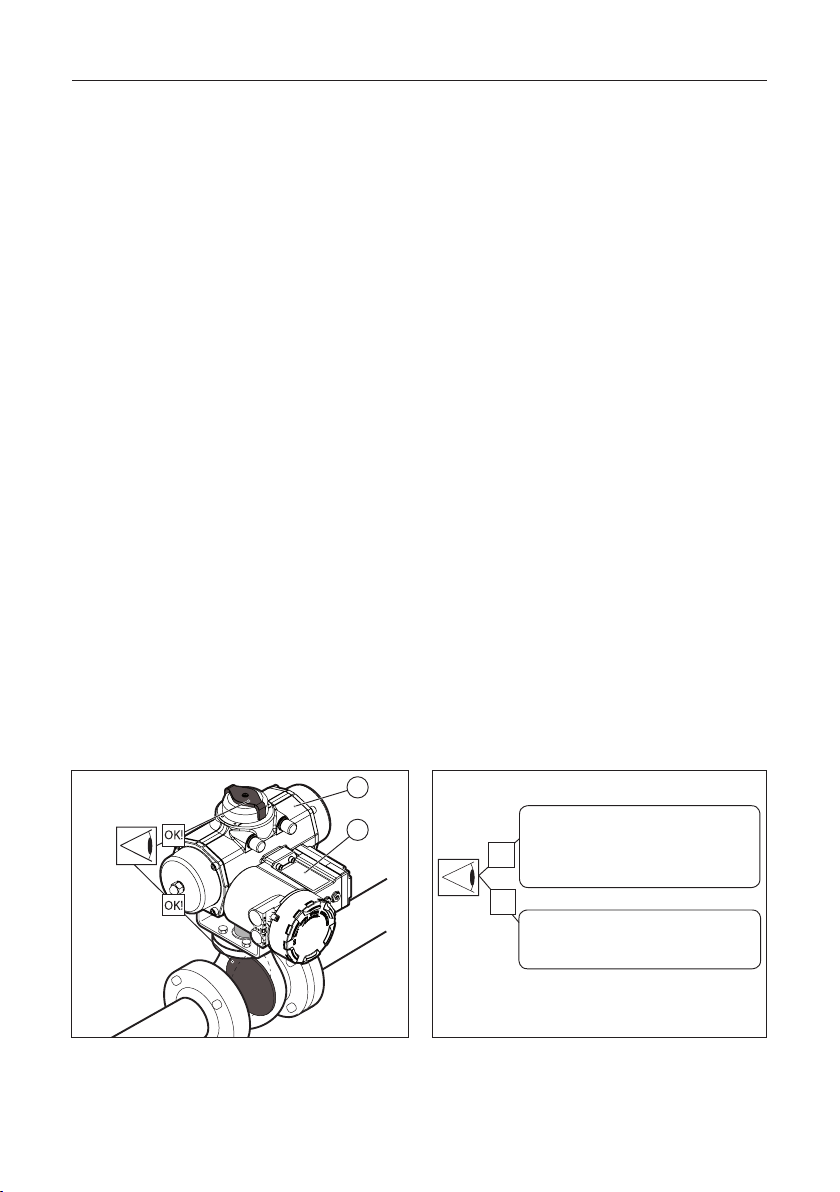
* Check the module label for the right execution
(see figure 2.2)
* Check the type of actuator: single or double
acting (see figure 2.2).
* For mechanical installation of the module see
installation instruction leaflet DOC.QC4.MTI.1,
as shipped with the module.
* If you have any questions regarding these
instructions, contact your Emerson sales office
before proceeding as shipped with the module.
1
2
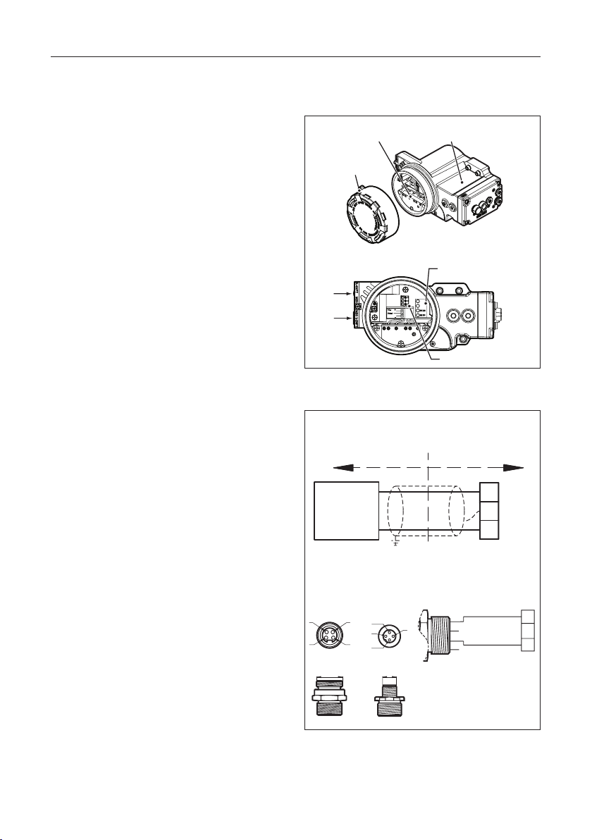
Fig. 2.1 Check proper mounting before connecting air
supply and electrical wiring.
2
Control Module Label =
QC40..WP.. = ASI
OK
QC40..x4.. = ASI Non Incendive /
Non Sparking
OK
Actuator Label =
QS xxxx = Single acting (Spring Return)
QD xxxx = Double acting
Note: x is variable based on the certification type.
Fig. 2.2 Identification
Page 3
Installation guide
DOC.IG.QC40.1 Rev. 3
FieldQ
May 2018
2.1 Mechanical alignment and mounting of
the control module
The control module is equipped with an alignmentedge on top of the module.
This allows easy alignment and mounting of the
control module on to the actuator housing.
Procedure: (see figure 2.3)
1. First take care that both mating faces from the
actuator and control module are clean and free
of dirt.
2. Check if the module has the required function
3. Remove the transparent film from the
control module.
4. Ensure seals are placed correctly.
5. Level the screws with the surface.
6. Place the alignment-edge (1) of the control
module at the top of the pneumatic interface.
7. Flip the module down taking care that the IPT
Probe (2) on the actuator fits in the mating hole
on the control module and loosely place
the screws.
8. Tighten screws according force in sequence.
Tightening moments
The Control Module should be fastened by using an
Allen key and applying the following
tightening moments:
- Allen Key: No 5
- Torque: 6.1 to 6.6 Nm (54 - 58.4 In.lbs)
Alignment-edge
(1)
Alignment-edge
IPT probe
(2)
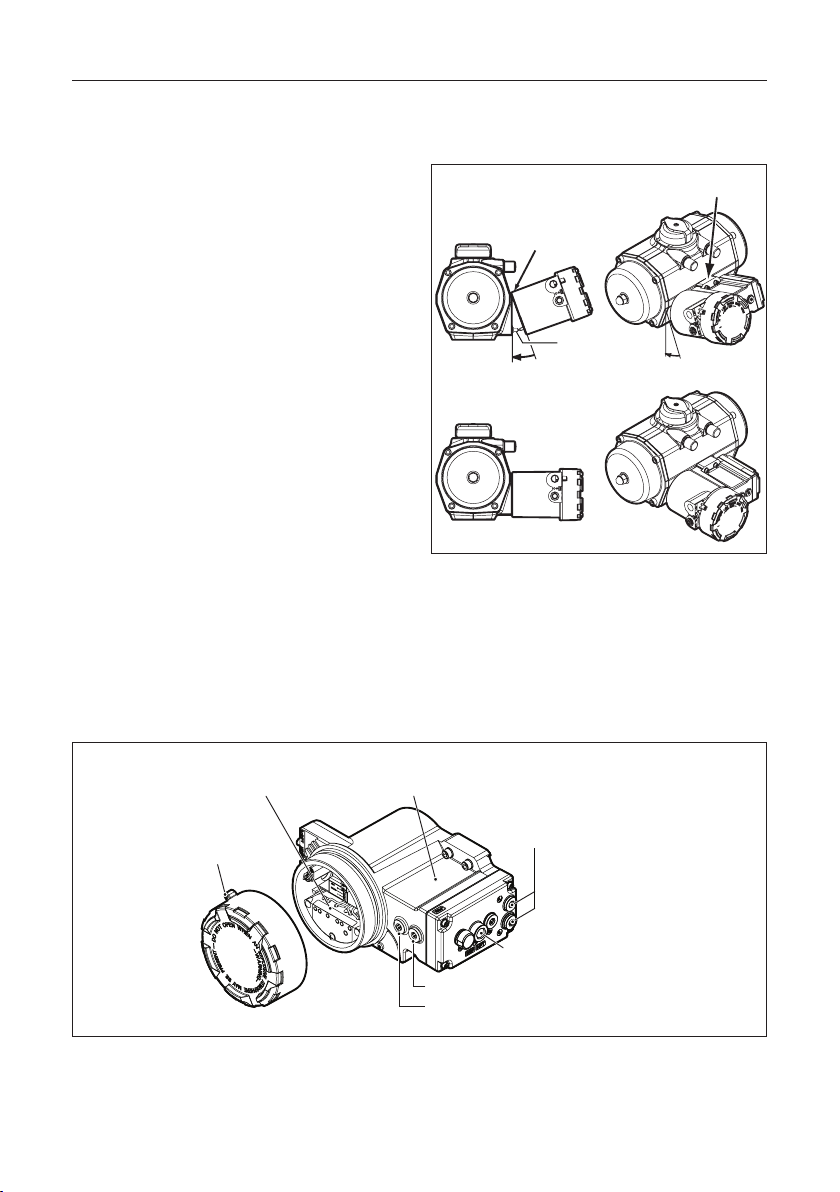
Fig. 2.3 Alignment and mounting of control
module to actuator
Terminal compartment with:
- AS-I cartridge and
- switch cartridge
Lockable
Module cover
Fig 2.4 Control module overview
Control Module
Type Label
Pneumatic connections
Option: Local Manual Control
Option: Additional Local Manual Control
for “Fail in Last Position”
Option: 1 or 2 speed
control throttles
3
Page 4
FieldQ
May 2018
3 Pneumatic connections
Installation guide
DOC.IG.QC40.1 Rev. 3
IMPORTANT
1 The actuator/valve combination can move
after connecting the air supply.
2 Ensure that the QC40 control modules are
mounted properly to the actuator to achieve
good functioning and the required ingress
protection, before connecting the air supply.
3 Check that the maximum supply pressure
P
= 8bar/116Psi
max
4 Be sure that the minimum required supply
pressure for the application is available at
the actuator.
5 Take appropriate measures to prevent
condensation or moisture to entering the
actuator or the control module. Condensation
or moisture can damage these components
and can result in failures.
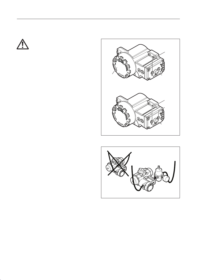
6 The exhaust ports Ra and Rb on the module
(see figure 3.1) are shipped from the factory
with transport protection.
* If ingress protection IP66 or NEMA 4X is
required, appropriate connections must be
used in exhaust ports Ra & Rb.
3.1 Operating media :
* Air or inert gasses.
* Air filtered at 50μm.
* Dew point 10 K below operating temperature.
* For subzero applications take
appropriate measures.
3.2 Single acting (spring return) or Double
acting actuator :
1 Remove the transport sticker from the
air supply (Ps).
2 Connect air supply to port (Ps).
Single acting
Control
Module cover
Double acting
Fig. 3.1 Pneumatic connections
OK
Fig 3.2 Install drip loops
Ra
Ps
1/4” BSP or
1/4” NPT
Ra
Rb
Ps
1/4” BSP or
1/4” NPT
50µm
4
Page 5

Installation guide
DOC.IG.QC40.1 Rev. 3
4 Electric Connections
FieldQ
May 2018
Table 4.1 Electrical data QC40 - ASI
Protocol AS-Interface Spec3.0
Maximum Voltage 31.6V
Minimum Current
(pilot valves off)
Nominal Current
(one pilot valve
activated)
Maximum Current
Consumption
(one pilot valve
application)
Maximum Current
Consumption
(two pilot valves
application)
Protection Short circuit detection
Note:
The current consumption of feedback switches is included.
Check the product data sheet for one or two pilot valves application.
Environmental conditions :
Temperature *
Humidity
Altitude
Use In- and outdoor.
34mA at 26.5V
85mA at 26.5V
125mA at 26.5V
140mA at 26.5V
Ambient: -25°C to +60°C
(-4°F to +140°F)
Maximum Surface: 80°C (176°F)
0 to 85% at 25°C(+77°F) derate
to 50% above 40°C (104°F)
(non-condensing).
Operating full power available
up to 2000 meter (6000 feet).
Table 4.2 Wiring dimensions
Wire type: Dimensions:
Cable range 0.33 - 2.5mm2 or 22 - 12AWG
Please check www.as-interface.net for various
application guides like installation and wiring
guidelines.
Table 4.3 Tools
Screw: Tool:
Terminals Screw driver: 0.6 x 3.5
Earth screws
Screw driver for cross slotted
Phillips screws nr. 2.
WARNING:
* If the Control Module is used in a manner not
specified by the manufacturer, the protection
provided by the equipment may be impaired.
* If required, mount earth wire (1) between top
(2) and bottom (3) ring of earth wire
connection (see figure 4.1).
4.1 Electrical data for hazardous area
executions
Please check chapter 10 for electrical data and
instructions in case an “Non Incendive/Non Sparking”
Control Module is used in hazardous locations
(Zone 2 or Class I Div.2).
* In case the Control module is used in Hazardous
locations, check the Control Drawings as per
chapter 10 for the applicable temperature range.
* The current restricted power supply meets NEC
Class 2, as described by the National Electrical
Code® (ANSI/NFPA 70 (NEC®))
Fig. 4.1 Earth wire connections
5
Page 6
FieldQ
May 2018
Installation guide
DOC.IG.QC40.1 Rev. 3
4.2 Procedure
1 Remove Control Module cover (see figure 4.2).
2 Guide the cable(s) through the electrical
entry(ies).
- Use and mount cable glands as required by
national or local legislation.
- When IP66/NEMA4X ingress protection is
required, the electrical entries must be fitted
with glands rated IP66/NEMA4X or higher.
3 Make the electrical connections as shown in
figure 4.3.
- For hazardous area connections, see the
instructions in chapter 10
- Quick connectors, as shown below, are allowed
to be used only for non-explosion safety
product application
4 Mount the function module cover to the housing
(see figure 4.2) or continue with chapter 5. Take
care that the cover seal is in place to comply to
dust and water tightness according to IP66 /
NEMA4X.
Terminal
compartment
Lockable
Module cover
Electrical entries:
3/4”NPT
or M20
1/2”NPT
or M20
Control Module
Type Label
LED’s for Fault, Power,
Open and Close position
FAULT
POWER
Wiring Terminals
Fig. 4.2 Terminal connections behind cover.
AS-I terminal wiring connections:
QC40 AS-I control module
Field wiring Actuator wiring
AS-I
Power
supply
Note: Terminal 2 can be used for shield.
+
1
2
-
3
Quick connector pinouts:
(male chassis part)
Brown
1
3
4
3
2
1
4
2
M127/8" UNC
1
3
Blue
Quick
connector option
Connect only the brown and
blue wires. Where applicable,
cut away unused wires.
Fig. 4.3 Terminal connections and quick
connector pinouts
1
2
3
Terminals
6
Page 7

Installation guide
DOC.IG.QC40.1 Rev. 3
5 Commissioning
FieldQ
May 2018
In order to commission the QC40 ASI Control
Module, the following actions must be considered
or done:
1 Re-adjustment of the limit switch points if the
factory setting do not meet the application
requirements
2 Addressing of the QC40 ASI Control Module
5.1 Re-adjustment of the limit switch points
5.1.1 Factory switch point settings
Mechanical stroke: 90°±0.5° (Actuator setting)
Switch points: ± 15° before each end of
Adjustable range: -20° to +3° at each end.
Switch points
stroke (open and closed
position, see fig 5.1).
3°
20°
Closed
90°
20°
Open
3°
Fig. 5.1 Adjustable range
If required the mechanical stroke and the limit
switch setting can be re-adjusted.
- For mechanical stroke adjustment of the actuator,
please see document DOC.IOM.Q.E, available
from www.emerson.com/fieldq.
- For re-adjusting the limit switches,
see procedure below.
5.1.2 Before re-adjusting the limit switch points
IMPORTANT
* Before mounting the actuator on the valve, be
sure that both the actuator and the valve have
the same “open” or “closed” position.
* Set the Mechanical stroke before setting the
limit switches.
5.1.3 Pneumatic and electrical connections
Make pneumatic and electrical connections before
adjusting the limit switch setting.
See chapter 3 and 4.
5.1.4 Switch point setting and valve
rotation direction.
The QC40 ASI Control Module is equipped with
non-intrusive switch point adjustment. The
adjustment screws are accessible behind a shield in
the front of the module (see fig 5.2).
This means that the switch point adjustment can be
done without opening the module.
Normally valves are “Closed” after a
clock wise rotation.
- In this case the top adjustment screw (see
fig. 5.2), sets the switch point of the “Closed”
position and bottom adjustment screw sets the
switch point of the “Open” position.
- For a valve that is “Open” after a clock wise
rotation, the position feedback will be reversed.
The table below indicates which re-adjustment
screw is related to the “Open” or “Closed” switch
point setting.
Table 5.1 Re-adjustment screws
Re-adjustment
screw :
Bottom Open position Close position
Top Close position Open position
Valve movement
“Close” after
a clock wise
rotation
“Open” af ter
a clock wise
rotation
7
Page 8

FieldQ
May 2018
Installation guide
DOC.IG.QC40.1 Rev. 3
5.1.5 Working principles Switch Operating
Mechanism (see fig 5.2)
The Switch Operating Mechanism is intend to
operate the position feedback switches and allows
adjustment of the switch points in the open and
closed end positions. Factory setting is that the
switches are activated 15° before the end of the
open and closed stroke.
Switch Operation
The rotation of the actuators pinion operates the
IPT device (1) which results in a linear movement.
The linear movement of the IPT device operates
lever (3). The lever amplifies the linear movement
of the IPT device and operates the switch operating
rod (5). Dowel pin (6) in the rod operated the levers
of the open and closed switch elements (8 & 9).
8
6
7
5
The lever is of the “floating” type. When the IPT
device operates the lever, it moves completely
upwards until it meets the upper pivot block (4). At
this point the lever will tip over and pull down the
switch operating rod (5) and operates the
bottom switch (7). When the IPT device moves
back the springs cause the lever to move
completely downwards until it meets the lower
pivot block (2). At this point the lever will tip over
and push up the switch operating rod (5) and
operates the top switch (8).
Switch point adjustment
The position of the lower pivot block (2) can be
changed by adjustment screw (10) and the position
of the upper pivot block (4) can be changed by
adjustment screw (9).
By adjusting the position of these pivot blocks the
switch points will be changed.
The adjustment screws (9 & 10) can be found
behind the shield (12) in front of the module. To
access the adjustment screws loosen the screw (11)
and rotate the shield (12) as shown.
H
E
W
N
N
E
E
N
N
I
P
N
R
G
A
E
O
!
W
R
-
-
T
G
O
I
10
9
15
N
O
D
Z
E
D
4
3
10
9
2
1
11
12
Fig. 5.2 Working principles Switch Operating Mechanism
8
Page 9

Installation guide
DOC.IG.QC40.1 Rev. 3
FieldQ
May 2018
5.1.6 Re-adjustment of switch points
IMPORTANT
The procedure below assumes:
- That the actuator and control modules are
according the factory settings.
- If th e switch setting is somehow lost or forgotten,
then consult paragraph 6.3 to set the switch point
setting back to factory setting.
- That the actuator / valve assembly is closed
after a clock wise rotation (see chapter 5.1.4).
Below procedure assures that the position feedback
complies more accurately with the valve position
and will set the switch point at approximately 4°
before the end of the stroke.
To set and detect the Open or Closed switch points,
the QC40 AS-I module has two LED’s that light
up if the Open or Closed position limit switch is
activated.
Procedure (see fig 5.3):
1. Loosen the screw (1) of the shield (2) and turn
the shield down.
Closed Position:
2. Send an “Close” command to the ASI module,
wait and make sure the valve has moved to
closed position.
3. Turn top screw (3) counter clock wise (do not
force the adjustment screw) until the switch
trips and the corresponding LED (5) goes out.
4. Turn top screw (3) clock wise (do not force the
adjustment screw) until the switch trips and
the corresponding LED (5) goes on. This position
represents the actual, mechanical “closed”
position of the valve.
5. Turn the screw minimal a 1/2 turn clock wise.
The “closed” position switch point is now set.
Open Position:
5. Send an “Open” command to the ASI module,
wait and make sure the valve has moved to open
position.
6. Turn bottom screw (4) clock wise (do not force
the adjustment screw) until the switch trips
and the corresponding LED (6) goes out.
7. Turn bottom screw (4) counter clock wise
(do not force the adjustment screw) until the
switch trips and the corresponding LED (6) goes
on. This position represents the actual “open”
position of the valve.
8. Turn the screw minimal a 1/2 turn counter clock
wise. The “open” position switch point is now set.
9. Turn the shield (2) back over the adjustment
screws and fasten it with the screw (1).
Important:
During switch point adjustment, do not force the
adjustment screws when you feel an obstruction.
Forcing the adjustment screws can damage the
cross head of the adjustment screw.
Table 5.2 Tool table
Shield screw Cross slotted Phillips nr. PH2
Adjustment screws
5
6
0.6 x 3.5 or
Cross slotted Phillips nr. PH2
FAULT
POWER
3
4
1
2
“Closed”
Switch point adjustment
FAULT
POWER
6
Note:
360° rotation of adjustment screw is
±8° adjustment of switch point.
“Open”
Switch point adjustment
FAULT
POWER
5
Fig. 5.3 Re-adjustment screws for “Open” and
“Closed” position feedback
9
Page 10

FieldQ
May 2018
Installation guide
DOC.IG.QC40.1 Rev. 3
5.2 Addressing
The QC40 ASI module supports the ASI-3 profile.
When a module ships from the factory, it has the
slave address “0”.
The slave address can be changed using a master
device. Please check the applicable sections of the
documentation supplied with these devices.
Table 5.2.1 Programming notes:
Factory address 00 EID1 7
IO-Code 6 EID2 E
ID-Code A Parameter 00
Q-Series data bits Functions
Typ e DI’s DO’s
D0 Bi-directional
D1 Bi-directional
Feedback
“Closed”
Feedback
“Open”
Solenoid 2
Control
Solenoid 1
Control
D2 Bi-directional Not used
D3 Bi-directional Not used
5.2.2 Diagnostics
- The ASI communications watchdog is activated.
- The control electronics in the module are
monitored for short circuit.
- Diagnostics information is communicated via
ASI slave status LEDs and Master (see table 3)
Red
Green
FAULT
POWER
FAULT
POWER
Fig. 5.4 ASI slave status LEDs
Table 5.2.2 ASI slave status LEDs (see figure 5.4)
Flags in the master Possible reason Suggested action
Config.
Error
Periphery
Fault
Symptom
Normal
operation
Indication at
the slave LEDs
Green Red
On Off reset reset Everything OK -/-
On On set reset Master in STOP Mode
No data
exchanges
“Slave not in LPS
Slave with wrong IO/ID
Reset at Slave active
Slave address = 0”
Serious
peripheral error
with reset
On Blinking set undefined
Short circuit or line
break
10
Check master
configuration
Check slave
configuration
Contact Emerson
Actuation Technologies
Page 11

Installation guide
DOC.IG.QC40.1 Rev. 3
FieldQ
May 2018
5.3 Check operation
5.3.1 Default (single) pilot valve operation
1. For function test, the unit must be connected to
an ASI master device or an ASI gateway.
2. Connect pressure according chapter 3 and the
ASI bus signal according chapter 4.
3. For sending the “Open” or “Closed” command,
check the applicable sections of the
documentation supplied with the ASI master
device or the ASI gateway.
4. Send an “Open” command to the Solenoid 1 DO
(Data bit D1) of the ASI module.
5. Actuator moves to “Open” position.
6. Send an “Close” command to the Solenoid 1 DO
(Data bit D1) of the ASI module.
7. Actuator moves to “Closed” position.
8. Mount the Control Module cover to the housing
(see figure 3.1).
5.3.2 Dual pilot valve (Fail in Last Position)
operatation
Important:
The QC40 ASI Control module with Dual Pilot valves
has only the Fail-in-Last-Position function when the
module is mouted to a double acting actuator.
1. For function test, the unit must be connected to
an ASI master device or an ASI gateway.
2. Connect pressure according chapter 3 and the
ASI bus signal according chapter 4.
3. For sending the “Open” or “Closed” command,
check the applicable sections of the
documentation supplied with the ASI master
device or the ASI gateway.
4. Send an “Open” command to the Solenoid 1
DO (Data bit D1) of the ASI module while “Close”
command to Solenoid 2 DO (Data bit D0).
5. Actuator moves to “Open” position.
6. Remove the ASI wiring from the module
terminals.
7. The double acting actuator should not rotate.
8. Re-connect the ASI bus signal according
chapter 4.
9. Send an “Open” command to the Solenoid 2
DO (Data bit D0) of the ASI module while “Close”
command to Solenoid 1DO (Data bit D1).
10. Actuator moves to “Closed” position.
11. Remove the ASI wiring from the
module terminals.
12. The double acting actuator should not rotate.
13. Mount the Control Module cover to the housing
(see figure 3.1).
11
Page 12

FieldQ
May 2018
6 Trouble shooting
Installation guide
DOC.IG.QC40.1 Rev. 3
6.1 The “Open” and “Closed” position
feedback signals are reversed from the
actual valve positions.
1 Check if the actuator is correctly mounted to
the valve.
Before mounting the actuator on the valve, the
actuator and the valve should have the same
“open” or ‘closed” position (see Installation &
Operation Manual FieldQ Valve
Actuator DOC.IOM.Q.E).
2 Some valves may be operated in such a way that
they are:
- “Open” after a clock wise rotation and
- “Closed” after a clock wise rotation.
3 Please see § 5.1 for setting the “Open” and
“Closed” position feedback signals
6.2 The actuator does not give (good)
position feedback signals.
1 Check if the actuator is correctly mounted to
the valve.
2 Re-adjust the limit switch setting as per
chapter § 5.1
6.3 Factory setting of the switch points.
IMPORTANT
The procedure below assumes:
- That the actuator / valve assembly is closed
after a clock wise rotation (see also § 5.1).
- The control module is pneumatically and
electrically connected according
chapter 3 and 4.
This procedure sets the switch point settings of the
switches, back to the factory settings (±15° before
each end of stroke), assuming a mechanical stroke
of 90°±0.5° of the actuator.
To set and detect the Open or Closed switch points,
the QC40 AS-I module has two LED’s that light
up if the Open or Closed position limit switch is
activated.
Procedure (see fig 5.3):
1. Loosen the screw (1) of the shield (2) and turn
the shield down.
Closed Position:
2. Send an “Close” command to the ASI module.
3. Turn top screw (3) counter clock wise maximum
20 turns, (do not force the adjustment screw)
until the switch trips and the corresponding LED
(5) goes out.
4. Turn top screw (3) clock wise 1 3/4 turn (do not
force the adjustment screw). The “closed”
position switch point is now set to factory setting.
Open Position:
5. Send an “Open” command to the ASI module.
6. Turn bottom screw (4) clock wise maximum 20
turns, (do not force the adjustment screw)
until the switch trips and the corresponding LED
(6) goes out.
7. Turn bottom screw (4) counter clock wise 1 3/4
turn (do not force the adjustment screw) The
“open” position switch point is now set to
factory setting.
8. Turn the shield (2) back over the adjustment
screws and fasten it with the screw (1).
Important: Do not force the adjustment
screws
During switch point adjustment, do not force the
adjustment screws when you feel an obstruction.
Forcing the adjustment screws can damage the
cross head of the adjustment screw.
12
Page 13

Installation guide
DOC.IG.QC40.1 Rev. 3
7 Maintenance 8 Optional Controls
FieldQ
May 2018
The FieldQ control modules are designed to operate
without maintenance. For any further maintenance
to the actuator see Installation & Operation Manual
FieldQ Valve Actuator, DOC.IOM.Q.E or contact
your local FieldQ representative.
Installation, adjustment, putting into service, use,
assembly, disassembly, maintenance and repair of
the control module must be done by
qualified personnel.
For any further maintenance to the control module
see Maintenance Manual, DOC.MM.QC40.E or
contact your local FieldQ representative.
Installation, adjustment, putting into service, use,
assembly, disassembly, maintenance and repair of
the control module must be done by the
qualified personnel.
WARNING
!
• Substitutionofcomponentsmayimpair
suitability of the equipment
Location for 2nd
Manual Control
Lock
45°
Unlock
On
Off
Default location
of Manual Control
8.1 Manual Control options
(see figure 8.1)
For commissioning, emergency or maintenance
purposes, the FieldQ can be supplied with one or two
Manual Control options. These can operate the spool
valve(s) inside the module and as such operate the
actuator, when there is air pressure available, but no
control signal or power supply.
8.1.1 Mounting Manual Control
1 To add a Manual Control, remove the plug(s) in
front of the module and turn in the
Manual Control.
- For normal operation the module should be
fitted with one Manual Control.
- For Double Acting with a Fail-in-Last-Position
function, two Manual Control can be fitted.
8.1.2 Manual Control operation
1 The Manual Control has a
“Push & Lock” function:
- To operate the Manual Control, use a screw
driver, push to activate and release to
de-activate the pilot valves.
- If required turn it 45°, to lock it in position
and keep the actuator in its operated state.
2 In case of a Fail in Last Position configuration
with two manual controls:
- The manual control on the right side (default
location) will pressurize the central air
chamber and cause the actuator to rotate
counter clock wise. For reverse acting
FieldQ actuators (Assembly code CC) the
actuator will rotate clock wise.
- The manual control on the left side (Location
for 2nd Manual Control) will pressurize the
end cap air chambers and cause the actuator
to rotate clock wise. For reverse acting FieldQ
actuators (Assembly code CC) the actuator
will rotate counter clock wise.
- In order to operate one of the manual
control, be sure the opposite manual control
is de-activated and unlocked.
Fig. 8.1 Local Manual Control options
13
Page 14

FieldQ
May 2018
Installation guide
DOC.IG.QC40.1 Rev. 3
9 Related Information
8.2 Speed control option
(see figure 8.2)
The FieldQ can be supplied with a Speed Control
option. One throttle is required for Spring Return
actuators and up to two for
Double Acting actuators.
The speed control throttle controls the air flow in
and out of an air chamber and as such limits the
speed of the “Opening” and “Closing”
stroke simultaneously.
8.2.1 Mounting Speed Control throttle(s):
1 Remove the plug(s) at the side of the module
and turn in the throttle (1).
2 Spring Return actuators: Use the top entry only.
3 Double acting actuators: Use both bottom and
top entries.
- For standard actuators, the top entry will
throttle the closing stroke.
- For standard actuators, the bottom entry will
throttle the opening stroke.
- For reverse acting actuators, the opposite
strokes will be throttled.
8.2.2 Adjusting Speed Control throttle(s):
1 Remove the nut cap (2).
2 Clockwise rotation of the adjustment screw
reduces the speed.
3 Counter clockwise rotation of the adjustment
screw increases the speed.
4 Replace the nut cap.
Other documents containing information related to
the FieldQ Module include:
- 1.604.13: QC40 AS-I Control Module data sheets
- DOC.IOM.Q.E: Installation Operation &
Maintenance Manual.
These documents are available, in multiple
languages, for download go to
www.emerson.com/fieldq
9.1 Applied IECEx standards
The following standards are applied:
- For FieldQ Control Module QC40...P4... ,
IEC 60079-0 Ed. 6.0 : 2011
IEC 60079-15 Ed. 4.0 : 2010
IEC 60079-31 Ed. 2.0 : 2013
9.2 RoHS Directive
This product is only intended for use in large
scale fixed installation excluded from the scope
of Directive 2011/65/EU on the restriction of
the use of certain hazardous substances in
electrical and electronic equipment (RoHS 2).
2
Fig. 8.2 Speed control operation
14
Spring Return:
Top entry only.
Double Acting:
Bottom and/or top
entries.
1
Page 15

Installation guide
DOC.IG.QC40.1 Rev. 3
10 EU Declaration of Conformity
FieldQ
May 2018
Legal representative entity for the
European Union:
Emerson Process Management, Valve Automation
Asveldweg 11, 7556 BR Hengelo Netherlands
ROC nr 8460
Rev. 0
FieldQ
EU DECLARATION OF CONFORMITY
Issued in accordance with the
EMC Directive 2014/30/EU, Appendix 1
ATEX Directive 2014/34/EU
We hereby declare, that the products specied below meet the basic health and safety requirements of the
above mentioned European Directives.
Product description: QC40 AS-I Control module
Serial number: Each Control module has an identiable serial number
Year of Construction: Each Control module has an identiable Year of Construction
Manufacturer: Emerson Machinery Equipment (Shenzhen) Co. Ltd.
Bao Heng Technology Industry Park Phase 2, North
Hong Lang 2nd Road District 68, Bao’an District,
518101 Shenzhen, China
EMC Directive 2014/30/EU
Typ es: QC40...
Applicable standards: IEC61326-1 : 2012 NAMUR Recommendations : NE21: 2004
ATEX DIRECTIVE
Typ es: QC40...P4...
ATEX Certicate No.: DEKRA 16ATEX0098 X
Marking:
Ta = -25°C ... +60°C
Applicable standards: EN 60079-0 : 2012 + A11:2013 EN 60079-15:2010 EN 60079-31:2014
Notied body: DEKRA Certication B.V., Notied body no : 0344
Meander 1051, 6825 MJ Arnhem, The Netherlands
II 3 G Ex nA IIC T4 Gc
II 2 D Ex tb IIIC T80°C Db
Signed:
____________________________
Name:
S. Ooi
Position:
Vice President, Global Marketing
& Pneumatic/Hydraulic SBU
Emerson, Actuation Technologies
Date:
2016-11-25
Place:EN
Houston TX, U.S.A.
15
Page 16

FieldQ
May 2018
Installation guide
DOC.IG.QC40.1 Rev. 3
11 QC40 ASI Smart Modules Non Incendive / Non sparking
11.1 Product marking
IECEx Hazardous or Classified Location
Certificate No.: DEK 16.0061 X
Non-Sparking
Ex nA IIC T4 Gc
Ex tb IIIC T80°C Db
ATEX Hazardous or Classified Location
Certificate No.: DEKRA 16ATEX0100 X
Non-Sparking
II 3 G Ex nA IIC T4 Gc
II 2 D Ex tb IIIC T80°C Db
FM Hazardous or Classified Location
Non Incendive
- Class I, II, III, Division 2,
Groups ABCDEFG, T4
- Class 1, Zone 2, Group IIC T4
CSA Hazardous or Classified Location
Certificate No.: CSA 17CA70125362X
Class I, Division 2, Groups A, B, C and D, T4;
Class II, Division 1, Group E, F and G, T80°C;
Class III, Division 1, T80°C
Ex nA nC IIC T4 Gc
Ex tb IIIC T80°C Db
Ambient temperature:
T4 @ Ta = -25°C...+60°C IP66/Nema 4X
Terminals
Lockable
cover
Do not open when
energized
Fig 11.1 Product marking
Type plate
11.2 ATEX / IECEx Intended use
• TheControlModuleQC40..P4..ofthe
FieldQ pneumatic actuator is a Group II category
3G (ATEX) equipment with protection level
Gc (IECEx).
• TheFieldQpneumaticactuatorsisaGroupII
category 2 equipment.
• Bothareintendedforuseinareasinwhich
explosive atmospheres caused by mixtures of air
and gases, vapors, mists or by air/dusts are likely
to occur.
• Thereforetheassemblymaybeusedin
hazardous area classified Zones 2 (Gasses)
and/or 21, 22 (Dust).
11.3 Safety instructions
WARNING
!
• Personalinjuryorpropertydamagecaused
by fire or explosion may occur if the module
is opened in any area which contains a
potentially explosive atmosphere or has been
classified as hazardous.
• Donotopenwhenmoduleisenergized.
• Preventanykindignitionduringinstallation,
adjustment, putting into service and use.
• Assembly,disassemblyandmaintenance
must be done in safe area’s without a
potential explosion hazard.
• Installation,adjustment,puttingintoservice,
use, assembly, disassembly and maintenance
or repair, shall be carried out in accordance
with the applicable code of practice by
suitably-trained personnel.
• Provisionsmustbemadetopreventthe
rated supply voltage being exceeded by
more than 40%.
• Potentialelectrostaticcharginghazard,clean
only with a damp cloth - danger of
propagating discharge.
• Theapparatusshallbeinstalledinsuchaway
that the risk from electrostatic discharges
and propagating brush discharges caused by
rapid flow of dust is avoided.
• Precautionshallbetakentoavoiddangerof
ignition due to electrostatic charges on the
marking plate of the enclosure.
16
Page 17

Installation guide
DOC.IG.QC40.1 Rev. 3
FieldQ
May 2018
• Substitutionofelectronicscartridge,switch
cartridge, pilot valve cartridge, pneumatic
cartridge, enclosure and seals must be with
parts from Emerson else the suitability for
Division 2 will be impaired.
11.4 CSA safety instructions
• The equipment may be used in zones 2 with
ammable gases and vapours with apparatus
groups IIA, IIB & IIC and with temperature
classes T1, T2, T3, T4.
• The equipment may be used in zones 21 &
22 with ammable dusts, bres and yings in
groups IIIA, IIB and IIC, with a layer autoignition temperature of not less than 75 K
above the maximum surface temperature
marked in the dust coding.
• There are no special checking or maintenance
conditions other than a periodic check.
• With regard to explosion safety, it is not
necessary to check for correct operation.
• If the equipment is likely to come into contact
with aggressive substances, e.g. acidic liquids
or gases that may attack metals or solvents
that may affect polymeric materials, then it is
the responsibility of the user to take
suitable precautions that prevent it from
being adversely affected thus ensuring that
the type of protection is not compromised.
11.5 Wiring instructions QC40 -
Non Incendive / Non Sparking
Protocol AS-Interface Spec3.0
Maximum Voltage 31.6V
Minimum Current
(pilot valves off)
Nominal Current
(one pilot valve
activated)
Maximum Current
Consumption
(one pilot valve
application)
Maximum Current
Consumption
(two pilot valves
application)
Protection Short circuit detection
* The current restricted power supply meets NEC
Class 2, as described by the National Electrical
Code® (ANSI/NFPA 70 (NEC®))
Terminal connections
Unclassified or Non
Hazardous Location
34mA at 26.5V
85mA at 26.5V
125mA at 26.5V
140mA at 26.5V
Hazardous or
Classified Location
AS-I
power
supply
+
-
Warning
* Explosion hazard. Do not disconnect
equipment when a flammable or
combustible atmosphere is present.
* Use installation wiring connections
with admitted maximum operating
temperature of at least 20 ºC (68°F)
higher than maximum ambient.
1
2
3
17
Page 18

FieldQ
May 2018
Installation guide
DOC.IG.QC40.1 Rev. 3
18
Page 19

Installation guide
DOC.IG.QC40.1 Rev. 3
FieldQ
May 2018
19
Page 20

World Area Configuration Centers (WACC) offer sales support,
service, inventory and commissioning to our global customers.
Choose the WACC or sales office nearest you:
NORTH & SOUTH AMERICA
19200 Northwest Freeway
Houston TX 77065
USA
T +1 281 477 4100
Av. Hollingsworth
325 Iporanga Sorocaba
SP 18087-105
Brazil
T +55 15 3413 8888
ASIA PACIFIC
No. 9 Gul Road
#01-02 Singapore 629361
T +65 6777 8211
No. 1 Lai Yuan Road
Wuqing Development Area
Tianjin 301700
P. R. China
T +86 22 8212 3300
For complete list of sales and manufacturing sites, please visit
www.emerson.com/actuationtechnologieslocations
or contact us at info.actuationtechnologies@emerson.com
MIDDLE EAST & AFRICA
P. O. Box 17033
Jebel Ali Free Zone
Dubai
T +971 4 811 8100
P. O. Box 10305
Jubail 31961
Saudi Arabia
T +966 3 340 8650
24 Angus Crescent
Longmeadow Business Estate East
P.O. Box 6908 Greenstone
1616 Modderfontein Extension 5
South Africa
T +27 11 451 3700
EUROPE
Holland Fasor 6
Székesfehérvár 8000
Hungary
T +36 22 53 09 50
Strada Biffi 165
29017 Fiorenzuola d’Arda (PC)
Italy
T +39 0523 944 411
www.emerson.com/fi eldq
©2018 Emerson. All rights reserved.
The Emerson logo is a trademark and service mark of Emerson
Electric Co. FieldQ
companies. All other marks are property of their respective
owners.
The contents of this publication are presented for information
purposes only, and while every effort has been made to ensure
their accuracy, they are not to be construed as warranties or
guarantees, express or implied, regarding the products or
services described herein or their use or applicability.
All sales are governed by our terms and conditions, which
are available on request. We reserve the right to modify or
improve the designs or specifications of our products at any
time without notice.
TM
is a mark of one of the Emerson family of
FieldQ
 Loading...