

Bettis Programming: TEC2 CCM Programming Using H-JTAG Software and H-JTAG Download Probe Part 1 Manuals & Guides
Page 1

Programming Instructions
TEC2-HJTAG-1001 Rev. 1
TEC2 CCM Programming Instructions
Using H-JTAG Software and H-JTAG Download Probe
September 2015
Page 2

Page 3

Programming Instructions
TEC2-HJTAG-1001 Rev. 1
Table of Contents
Section 1: TEC2 CCM Programming Instructions
1.1 Using H-JTAG Software and H-JTAG Download Probe..................................... 4
Appendix
Table of Contents
September 2015
Table of Contents
3
Page 4

Section 1: TEC2 CCM Programming Instructions
September 2015
Programming Instructions
TEC2-HJTAG-1001 Rev. 1
Section 1: TEC2 CCM Programming Instructions
1.1 Using H-JTAG Software and H-JTAG Download Probe
Figure 1 Bare Board Setup
Figure 2 CCM in LDM Housing Setup
NOTE:
Hjtag Probe has been modified. Software is available at http://www.hjtag.com/en/index.asp.
1. Connect the H-JTAG probe box and USB cable to the computer.
4
TEC2 CCM Programming Instructions
Page 5

Programming Instructions
TEC2-HJTAG-1001 Rev. 1
Figure 3 USB Cable Connected to Computer
Section 1: TEC2 CCM Programming Instructions
September 2015
2. Connect the H-JTAG probe box to the USB cable.
Figure 4 USB LED should light when USB Cable is connected to PC
and Probe. The TGT LED should light when the Ribbon cable is
connected between Board and H-JTAG Probe. ACT LED should light
when data is being transferred.
3. Connect the ribbon cable to the P10 JTAG connector on the CCM board.
TEC2 CCM Programming Instructions
5
Page 6

Section 1: TEC2 CCM Programming Instructions
September 2015
Figure 5 CCM Installed in LDM Setup
Programming Instructions
TEC2-HJTAG-1001 Rev. 1
Figure 6 Ribbon Cable on CCM Bare Board Setup – JTAG Ribbon on CCM
P10 Connector
4. On computer, run the H-JTAG software by doubling clicking the H-JTAG Icon.
6
TEC2 CCM Programming Instructions
Page 7

Programming Instructions
TEC2-HJTAG-1001 Rev. 1
Figure 7 Windows Desktop H-JTAG Icon
Section 1: TEC2 CCM Programming Instructions
September 2015
5. H-JTAG Server should start running.
Figure 8
TEC2 CCM Programming Instructions
7
Page 8

Section 1: TEC2 CCM Programming Instructions
September 2015
6. Click on the magnifying glass icon.
Figure 9 Correct Setup – Board Detected
Programming Instructions
TEC2-HJTAG-1001 Rev. 1
7. If you do not see the ARM7TDMI-S, ensure that the TGT LED and USB LED are both
lit on the H-JTAG Probe. See Figure 4 and check connections. See Appendix to supply power from probe, otherwise external power must be supplied.
Figure 10 Incorrect Setup – Board NOT Detected
8
TEC2 CCM Programming Instructions
Page 9

Programming Instructions
TEC2-HJTAG-1001 Rev. 1
8. Click on the F.
Figure 11
Section 1: TEC2 CCM Programming Instructions
September 2015
9. H-Flasher window will come up.
Figure 12
TEC2 CCM Programming Instructions
9
Page 10

Section 1: TEC2 CCM Programming Instructions
September 2015
10. For Step 1 Flash Selection, pick NXP.
Figure 13
Programming Instructions
TEC2-HJTAG-1001 Rev. 1
11. Pick NXP LPC2368.
Figure 14
10
TEC2 CCM Programming Instructions
Page 11
Programming Instructions
TEC2-HJTAG-1001 Rev. 1
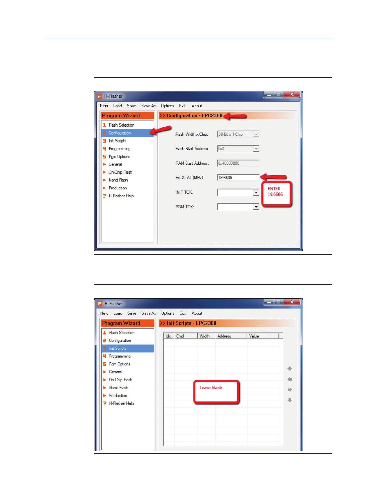
12. Click on Step 2 Configuration, enter 19.6606.
Figure 15
Section 1: TEC2 CCM Programming Instructions
September 2015
13. Click On Step 3, this screen should be blank. Delete anything entered here.
Figure 16
TEC2 CCM Programming Instructions
11
Page 12

Section 1: TEC2 CCM Programming Instructions
September 2015
14. Click On Step 4. Then click on Check button.
Figure 17
Programming Instructions
TEC2-HJTAG-1001 Rev. 1
12
TEC2 CCM Programming Instructions
Page 13

Programming Instructions
TEC2-HJTAG-1001 Rev. 1
15. You should see LPC2368 and ARM7TDMI-S for flash and target. If you do not see
Figure 18
Section 1: TEC2 CCM Programming Instructions
September 2015
this information, it means that the probe cannot see the target board and all connections should be checked. See Figure 4 above. The H-JTAG probe supplies the
power to the device being programmed. See the Appendix for instructions on how
to supply power from the probe. If the probe does not supply the power to the
board, the board must be powered externally for the download operation to work.
TEC2 CCM Programming Instructions
13
Page 14

Section 1: TEC2 CCM Programming Instructions
September 2015
16. Click on small arrow for “Type:”. Then select Plain Binary Format in drop down list.
Figure 19
Programming Instructions
TEC2-HJTAG-1001 Rev. 1
17. Click on the three small dots.
Figure 20
14
TEC2 CCM Programming Instructions
Page 15

Programming Instructions
TEC2-HJTAG-1001 Rev. 1
18. A new window will come up. Go to the directory and select which file to download
Figure 21 Find the directory the download file is located at.
to the board.
Section 1: TEC2 CCM Programming Instructions
September 2015
TEC2 CCM Programming Instructions
15
Page 16

Section 1: TEC2 CCM Programming Instructions
September 2015
19. Select the file to download.
Figure 22 Click on the file and then click on the Open button.
You should use the BIN type file.
Programming Instructions
TEC2-HJTAG-1001 Rev. 1
20. Click on Program button.
Figure 23 Hit Program Button
16
TEC2 CCM Programming Instructions
Page 17

Programming Instructions
TEC2-HJTAG-1001 Rev. 1
21. A small window will pop up and give you down load status.
Figure 24
22. Read the screen and verify that it Programmed and Verified Successfully, then Click
on the Close Button.
Section 1: TEC2 CCM Programming Instructions
September 2015
Figure 25
23. Remove the Ribbon cable from the board being programmed.
(See Figure 1 and Figure 2).
24. Remove the ribbon cable from the P10 of the CCM board.
25. Congratulations, the board is now programmed and is ready for use.
Programming More Boards:
To program more board(s), keep everything the same as above, and then repeat
these four instructions bellow:
26. Connect the JTAG ribbon cable to the new board to be programmed
(See Figures 5 and 6).
27. Click on the Check button. (See Figure 18).
28. Click on the Program button. (See Figure 23).
29. Read H-Flasher status window. (See Figure 25).
TEC2 CCM Programming Instructions
17
Page 18

Section 1: TEC2 CCM Programming Instructions
September 2015
Appendix
NOTE:
The H-JTAG probe used in these directions was modified from the original manufacturers
design to provide 5V on JTAG pin 19 to power the target device. This is how to modify the
H-JTAG probe. The JTAG specification allows for supplying power to the target on pin 19.
Figure 26 JTAG Pin Out
Programming Instructions
TEC2-HJTAG-1001 Rev. 1
20 PIN JTAG INTERFACE DESCRIPTION:
HTTPS://WWW.SEGGER.COM/INTERFACE-DESCRIPTION.HTML
1. Remove hidden screw under label.
Figure 27
18
TEC2 CCM Programming Instructions
Page 19

Programming Instructions
TEC2-HJTAG-1001 Rev. 1
2. Remove four Screws on board.
Figure 28
Section 1: TEC2 CCM Programming Instructions
September 2015
3. Remove board and connect 5V from USB connector to JTAG Pin 19.
Figure 29
TEC2 CCM Programming Instructions
19
Page 20

Section 1: TEC2 CCM Programming Instructions
September 2015
4. Exploded view of disassembled probe for reference. Big screw holds case together.
Reverse prior directions to reassemble the probe.
Figure 30
Programming Instructions
TEC2-HJTAG-1001 Rev. 1
5. New Black Style Boxes Modification.
Figure 31
20
TEC2 CCM Programming Instructions
Page 21

Programming Instructions
TEC2-HJTAG-1001 Rev. 1
These instructions were written for H-Flasher V3.0:
Figure 32
Section 1: TEC2 CCM Programming Instructions
September 2015
TEC2 CCM Programming Instructions
21
Page 22

Page 23

World Area Confi guration Centers (WACC) offer sales support, service,
inventory and commissioning to our global customers.
Choose the WACC or sales offi ce nearest you:
NORTH & SOUTH AMERICA
19200 Northwest Freeway
Houston TX 77065
USA
T +1 281 477 4100
Av. Hollingsworth
325 Iporanga Sorocaba
SP 18087-105
Brazil
MIDDLE EAST & AFRICA
P. O. Box 17033
Jebel Ali Free Zone
Dubai
T +971 4 811 8100
P. O. Box 10305
Jubail 31961
Saudi Arabia
T +966 3 340 8650
T +55 15 3413 8888
24 Angus Crescent
ASIA PACIFIC
Longmeadow Business Estate East
P.O. Box 6908 Greenstone
No. 9 Gul Road
#01-02 Singapore 629361
T +65 6777 8211
No. 1 Lai Yuan Road
1616 Modderfontein Extension 5
South Africa
T +27 11 451 3700
EUROPE
Wuqing Development Area
Tianjin 301700
P. R. China
T +86 22 8212 3300
Holland Fasor 6
Székesfehérvár 8000
Hungary
T +36 22 53 09 50
Strada Biffi 165
29017 Fiorenzuola d’Arda (PC)
Italy
T +39 0523 944 411
For complete list of sales and manufacturing sites, please visit
www.emerson.com/actuationtechnologieslocations or contact us at
info.actuationtechnologies@emerson.com
www.emerson.com/bettis
©2018 Emerson. All rights reserved.
The Emerson logo is a trademark and service mark of Emerson Electric Co.
TM
is a mark of one of the Emerson family of companies.
Bettis
All other marks are property of their respective owners.
The contents of this publication are presented for information purposes
only, and while every effort has been made to ensure their accuracy,
they are not to be construed as warranties or guarantees, express or
implied, regarding the products or services described herein or their use
or applicability. All sales are governed by our terms and conditions, which
are available on request. We reserve the right to modify or improve the
designs or specifications of our products at any time without notice.
 Loading...