


Multi-Port Actuator
Operation and Maintenance
Part Number: MPA-400-0313, Rev. N
Release: Mar 2013

WARNING:
Use caution when working on, with, or around valves and actuators. High pressures, forces, voltages, and
flammable media can be present.
WARNING
Read this manual in its entirety before installing, operating, or performing maintenance on the MPA valve
actuator.
WARNING
Failure to follow instructions for proper electrical wiring, storage, setup, and maintenance may cause
serious injury, damage equipment, or void the warranty. Refer to Manual E796 for instructions on storage,
electrical hook-up, and maintenance.
Ensure that the installation is carried out in accordance with EN 60079-14 and IEC 60079-14.
Regulatory information:
EEx d IIB T4 or EEx d IIB 120 degrees C (T4)
Tamb-20degress C to +60 degrees C
Revision N
Copyright © 2013
Emerson Process Management
All rights reserved.
II 2GD
Emerson Process Management
Valve Actuation LLC
13840 Pike Road
1-800-679-1561
(281) 499-1561 FAX (281) 499-8445

Operation and Maintenance
Part Number: MPA-400-0313, Rev. N
Table of Contents
Section 1: Introduction ........................................................ 1
Section 2: Features ...............................................................2
Section 3: Mechanical and Electrical Installation .................. 5
Section 4: Wiring ................................................................. 6
4.1 Power Wiring ................................................................................................ 6
4.2 Network Wiring ............................................................................................ 6
4.3 Monitor Relay Wiring..................................................................................... 6
4.4 Local ESD Wiring (Emergency Shutdown) ...................................................... 6
4.5 Optional Remote Display Module (RDM) Wiring ............................................ 7
Table of Contents
Mar 2013
Section 5: Local Display Module ........................................... 8
5.1 Description ................................................................................................... 8
5.2 Operation ..................................................................................................... 9
5.3 Local Operation ............................................................................................. 9
5.4 Operational Display ....................................................................................... 9
5.5 Display Blanking .......................................................................................... 10
5.6 Alarms Display ............................................................................................ 10
Section 6: Field Setup Using MPA Config Software .............. 12
6.1 CommSetUp ............................................................................................... 12
6.2 User Setup Menus ....................................................................................... 13
6.3 Selecting New Home Port (HP command using Control Knob setup) ........... 14
6.4 Home Port LED Function ............................................................................. 15
6.5 Home Port Calibration (HC command using Control Knob setup) ................ 15
6.6 Factory SetUp Menus .................................................................................. 16
6.7 Motor Type ................................................................................................. 16
6.8 Control Screen ............................................................................................ 18
Section 7: Field Setup Using Local Controls ......................... 20
7.1 Alarm History Display .................................................................................. 20
7.2 Setup Mode Display Sequence .................................................................... 20
Table of Contents
Section 8: Field Diagnostics ................................................ 23
8.1 Fd Fault Codes ............................................................................................. 23
Section 9: Remote Network Control ................................... 25
9.1 Modbus RTU ............................................................................................... 25
9.2 Foundation Fieldbus (FF) ............................................................................. 27
9.3 Probus DP Reduntant Networks with Redcom ........................................... 29
9.4 DeviceNet ................................................................................................... 30
I

Operation and Maintenance
Part Number: MPA-400-0313, Rev. N
Appendix A: EC Declaration of Conformity Certificate ......... 31
Appendix B: Wiring Diagrams ............................................ 32
B.1 Three Phase Power ...................................................................................... 32
B.2 Single Phase Power ......................................................................................33
B.3 24 VDC Power ............................................................................................. 34
Table of Contents
Mar 2013
II
Table of Contents

Operation and Maintenance
Part Number: MPA-400-0313, Rev. N
Section 1: Introduction
The Multi-Port Actuator is an single turn actuator for control of multi-port ow selectors
(MPFS) with 3 to 8 ports. A typical application is oil or gas well selection for well production
testing as shown in Figure 1. Typically the MPA is the actuator of a Multi-Port Flow Selector
as shown in Figure 2. There are applications in other processes where control of multi-port
valves is required.
Figure 1 Typical Well Test Application
Section 1: Introduction
Mar 2013
Figure 2 MPA mounted on 6"x16" MPFS
Introduction
1
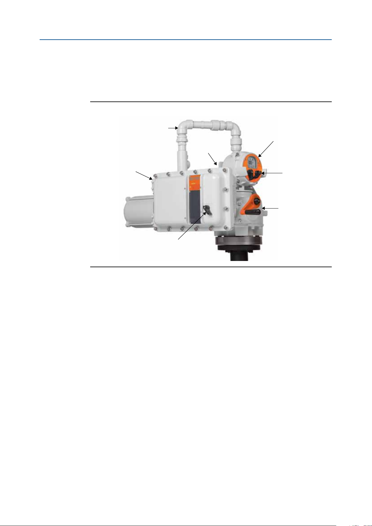
Section 2: Features
Low Voltage
Interfaces between
CPU and TBM
Electrical Enclosure with
Motor Starter, Control
Transformer, DC Power
Supplies, Power Entry,
Termination Panel, User
Wiring, I/O Interfaces,
Torque Encorder
Integral
Disconnect
BETTIS 3000 Ft-Lb Gearbox
Geared for 1.5 RPM
Position Encorder
Coupling to MPFS Stem
Local Display Module (LDM)
with Display & Status LEDs,
Selector & Control Knobs,
CPU Module,
Network Communications,
Position Encoder
Motor
(not shown)
Mar 2013
Section 2: Features
The actuator features several assemblies as shown in Figure 3. Unique features of the
actuator are listed below.
Figure 3 MPA Features
Operation and Maintenance
Part Number: MPA-0400-0313, Rev. N
• MPA uses Bettis’s heavy duty gearbox with capacity of 3000’ lbsThreaded Valve
Stem
— Wide range of motors available for any voltage and torque
• Congurable for multi-port ow selectors from 3 to 8 ports
— Any port may be selected as home port and any port(s) may be skipped
— Actuator calibrated at factory for exact match to alignment of ow
selector ports
— Calibration parameters stored in nonvolatile memory and available to DCS
• 12-bit magnetic encoder coupled directly to valve stem for precision position
feedback
— Provides position measurement resolution of 0.088 degrees
• BETTIS’s exclusive solid-state motor starter and control software provides precise
positioning of ow selector within +1 degree of selected port
• High performance microcontroller updates motor control output every 4mS for
precision motor control
• 12-bit magnetic encoder coupled directly to torque pinion for torque feedback
— Provides torque measurement resolution of 0.146% of full torque
2
Features

Operation and Maintenance
Part Number: MPA-400-0313, Rev. N
• MPA supports all network protocols available with all other Bettis actuators
• I/O and alarm monitoring include:
• Four models support ve 8-port MPFS (Also see motor type, Table 4)
Section 2: Features
Mar 2013
— Modbus RS485 Bus or E>Net ring available
— Probus Redundancy with Redcom
— Foundation Fieldbus
— DeviceNet
— Ethernet Modbus TCP/IP
— Integral circuit breaker/disconnect
— Motor overload and motor thermal
— Loss of control voltage
— Encoder failure
— Stall detection and alarming (detects mechanical faults)
— 3-Phase monitoring and phase correction to insure correct motor rotation
— ESD to send selector to home port (also goes to home port on fault)
— Monitor relay for hardwired relay contact status on fault
Table 1. Four models support five 8-port MPFS
Model MPFS
MPA 150 2x4 150 203 1.0 1.0 1.0 0.79
MPA 650 3x6 650 881 0.7 1.0 0.5 0.49
MPA 800 4x8 & 4x10 800 1085 0.6 0.9 0.5 0.40
MPA1500 6x16 1500 2034 0.3 0.5 0.3 0.26
Note: Accuracy based on worst case tests at 38% of maximum torque.
Capacity RPM Accuracy
Lb/Ft Nm 1Ph 3Ph DC Degrees
• MPA includes local display module (LDM) standard
— Uses rugged, high visibility LED display for port number, torque, and
alarms (also displays setup menus and setup parameters)
— Multiple color LEDs display
— Port position within 1° of port
— Port position within 2° of port
— Motor running
— Over torque
— Position within 0.25° of home port
— Local mode |
Features
— Off mode | Combined detection logic for two
selector switches
— Remote mode |
— Includes Local Off Remote selector switch
— Local control knob for Port selection and Jog control when enabled by
User
3
Section 2: Features
Mar 2013
Operation and Maintenance
Part Number: MPA-0400-0313, Rev. N
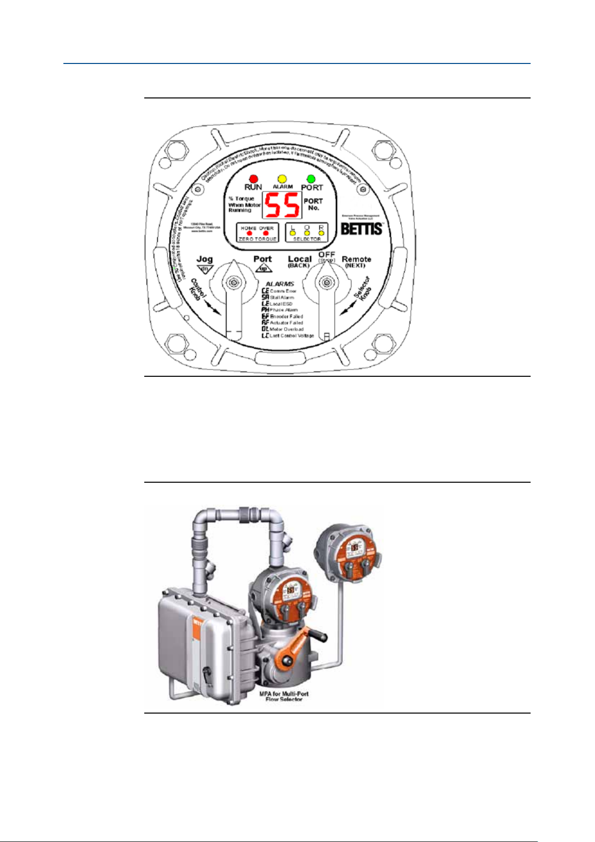
Figure 4 Local Display Module (LDM)
• Remote display module (RDM) option available
— RDM displays identical information and performs identical control as LDM
— BETTIS’s patented combined switch logic allows detection of selector
switch position on LDM and RDM
— Allows remote control up to 4,000 feet (1,220 meters) away
— Alarming includes loss of communication with RDM
Figure 5 MPA with Remote Display Module (RDM)
4
Features

Operation and Maintenance
Part Number: MPA-400-0313, Rev. N
Section 3: Mechanical and Electrical Installation
Section 3: Mechanical and Electrical
Installation
Do not connect power until you have gone through the following checklist
1. Does the information given on the nameplate correspond with the application?
2. Have all wire terminations and the equipotential bonding system been connected
correctly?
3. EEx d applications: are the cable entries, plugs and adaptors EEx d approved?
4. Are all cable entries of the correct internal diameter providing a good seal around
the cable?
5. Do the ambient and process temperatures correspond to the ratings on the
nameplate as shown below?
Mar 2013
Mechanical and Electrical Installation
5

Section 4: Wiring
Mar 2013
Section 4: Wiring
All user wiring terminations are made inside the Electrical Enclosure shown in Figure 3 on
Page 2. Refer to wiring diagram located at the back of this manual for wiring connections.
High voltage power connections are made to the disconnect/circuit breaker located inside
the electrical enclosure. All low voltage connections, including network wiring, are made
to the Termination Board Module (TBM) located inside the electrical enclosure. Use conduit
and seals in accordance with National Electric Code (NEC) and local codes for all wiring
entering the electrical enclosure.
4.1 Power Wiring
Connect power voltage leads to the circuit breaker located in the main electrical enclosure.
Power wires must enter the electrical enclosure at the conduit entry on the lower right side
of the enclosure to prevent water from entering. The controller provides automatic phase
correction in case three-phase power is connected in the wrong phase rotation.
4.2 Network Wiring
Operation and Maintenance
Part Number: MPA-0400-0313, Rev. N
If a single bus network connection, such as Foundation Fieldbus, is being made,
connect to Network Port A at TBM terminals 24 (-) and 25 (+). If the cable is shielded,
connect shield to TBM terminal 23. If redundant or repeater network connections such
as Bettis E>Net are being made, connect the second network to Network Port B at TBM
terminals 23 (+) and 24 (-). Connect cable shield of Port B to TBM terminal 25. Cable
shields are isolated from earth in the actuator. Connect shields to only one earth ground
point in the network, normally the host location.
4.3 Monitor Relay Wiring
The Monitor Relay is used for hard-wiring an indication of availability of the actuator for
remote control. When the selector switch is placed in the Remote mode and if there are no
alarms present that prevent operation, the Monitor Relay is energized. If an alarm occurs
or the selector switch is moved from the Remote position, the relay is de-energized. The
Monitor Relay is a Form C relay with both normally open (N.O.) and normally closed (N.C.)
contacts. Wire to either TBM terminals 31 and 32 if N.O. contacts are desired. Wire to TBM
terminals 32 and 33 if N.C. contacts are desired. The relay is shown on the wiring diagram
in the de-energized state, meaning that the actuator is not available for remote control.
4.4 Local ESD Wiring (Emergency Shutdown)
Remove jumper between TBM terminals 27 and 28. Connect Normally Closed (N.C.) dry
contacts to terminals 27 and 28. When the contacts open, ESD is activated, causing the
actuator to go to Home Port. The actuator will remain at the Home Port until the ESD
contacts are closed and a new command is received from either Local or Remote control.
The ESD circuit is a closed loop failsafe circuit. It the circuit is opened for any reason, broken
wire, bad contact, 24VDC power supply failure, etc., the ESD function is activated. The
closed loop circuit is powered by 24VDC from the actuator.
6
Wiring

Operation and Maintenance
Part Number: MPA-400-0313, Rev. N
Section 4: Wiring
Mar 2013
4.5 Optional Remote Display Module (RDM) Wiring
Connect twisted pair RS485 cable from the RDM to TBM terminals 18 (-) and 19 (+). If
the RDM is being powered from the actuator 12VDC supply, wire the power wires from
the RDM to TBM terminals 16 (-) and 17 (+). The RDM is polarity protected, preventing
damage, but will not operate if polarity is reversed.
Wiring
7
Section 5: Local Display Module
Mar 2013
Operation and Maintenance
Section 5: Local Display Module
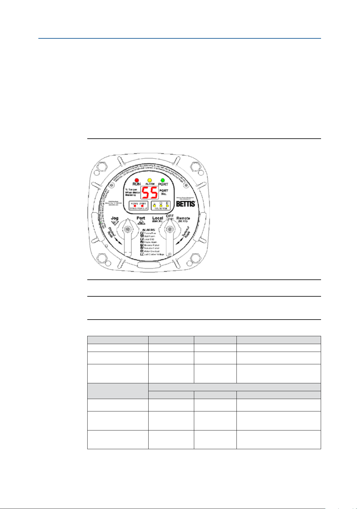
5.1 Description
Contains microprocessor controller, position encoder, and network interface. This is the
main controller used to setup and operate the actuator.
This module displays operating parameters, port position, torque, and alarms. It also
provides a means to congure the actuator by using the local controls.
Figure 6 Local Display Module
Part Number: MPA-0400-0313, Rev. N
To use the Local Control and Selector Knobs refer to Table 2.
NOTE:
Actuator moves in only the counterclockwise direction.
Table 2. Selector/Control Knob Function
Selector Knob (right) Rotate Function Results
OFF (Stop) [return position] Stop movement Prevents motor operation.
REMOTE (Auto) Clockwise Remote control
LOCAL (Hand) Counter-clockwise Hand Operation
Control
Knob (left)
Spring return Neutral position No operation
PORT (up) Clockwise
Jog (dn) Counter-clockwise
(while selector is in LOCAL (Hand) mode)
Rotate Function Results
Local command
to go to next
port
Local command
to micro-step
Allows control from remote
location.
Allows from the local control knob
or the control knob of the RDM, if
connected.
Releases a local command when
Local control is used.
Commands actuator to move to
the next port. Momentary knob
control.
Commands actuator to move only
whileknob is being held, i.e. maintained knob control.
8
Local Display Module
 Loading...