

Manual: Service Instructions Disassembly and Reassembly For G01 Through G10 Series Hydraulic Spring Return Actuators With M11 Hydraulic Override | Bettis
Bettis Manual: Service Instructions Disassembly and Reassembly For G01 Through G10 Series Hydraulic Spring Return Actuators With M11 Hydraulic Override | Bettis Manuals & Guides
Service Instructions
127072E Rev. C
October 2015
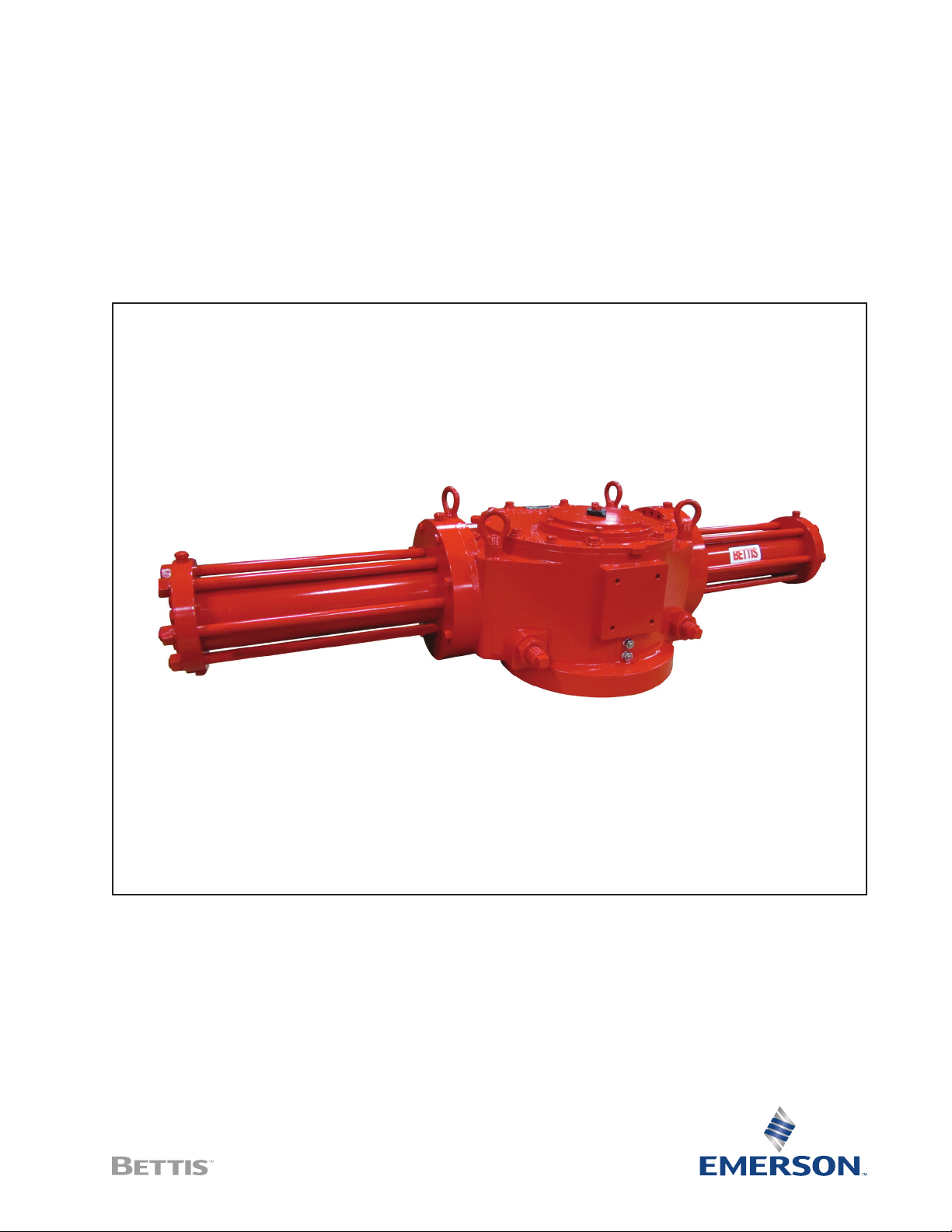
G01 through G10 Series Hydraulic Actuators
Spring-Return Actuators with M11 Hydraulic Override
Disassembly and Reassembly


Service Instructions
127072E Rev. C
Table of Contents
Section 1: Introduction
1.1 General Service Information .......................................................................... 1
1.2 Denitions .................................................................................................... 1
1.3 General Safety Information ........................................................................... 2
1.4 Bettis Reference Materials ............................................................................. 2
1.5 Service Support Items ................................................................................... 3
1.6 Lubrication Requirements ............................................................................. 3
1.7 Fluid Requirements ....................................................................................... 3
1.8 General Tool Information .............................................................................. 4
1.9 Actuator Storage ........................................................................................... 4
1.10 Actuator Installation ..................................................................................... 4
1.11 Actuator Start-up .......................................................................................... 4
1.12 Actuator Operation ....................................................................................... 5
Table of Contents
October 2015
Section 2: Actuator Disassembly
2.1 General Disassembly ..................................................................................... 6
2.2 Hydraulic Power Module Disassembly .......................................................... 6
2.3 Drive Module Disassembly ............................................................................ 7
2.4 G01 through G5 M11 Hydraulic Override Cylinder Disassembly ................... 10
2.5 G7 through G10 M11 Hydraulic Override Cylinder Disassembly ................... 10
Section 3: Actuator Reassembly
3.1 General Reassembly .................................................................................... 11
3.2 Drive Module Disassembly ..........................................................................11
3.3 Hydraulic Power Module Reassembly ..........................................................16
3.4 G01 through G5 M11 Hydraulic Override Cylinder Reassembly .................... 18
3.5 G7 through G10 M11 Hydraulic Override Cylinder Reassembly .................... 18
3.6 Actuator Testing ......................................................................................... 20
Section 4: Field Conversions
4.1 Fail Mode Reversal (CW to CCW or CCW to CW) .......................................... 21
4.2 Convert Double-Acting Actuator to
Spring-Return with M11 Module ........................................................................... 21
Section 5: Module Removal and Installation
5.1 M11 Override Cylinder Removal .................................................................. 22
5.2 M11 Override Cylinder Installation .............................................................. 23
5.3 Spring Module Removal ..............................................................................24
5.4 Spring Module Installation .......................................................................... 25
5.5 Hydraulic Power Module Removal .............................................................. 27
5.6 Hydraulic Power Module Installation ..........................................................28
5.7 G2 through G10 Powr Swivl™ Removal ....................................................... 29
5.8 G2 through G10 Powr Swivl Module Installation .......................................... 29
ITable of Contents

Table of Contents
October 2015
Section 6: Actuator Support Information
Section 7: Troubleshooting
Section 8: Removal and Decommissioning
Service Instructions
127072E Rev. C
6.1 Module Volume Table .................................................................................31
6.2 Module Weight Tables ................................................................................. 31
6.3 G01 Tool Table ............................................................................................ 33
6.4 G2 Tool Table .............................................................................................. 33
6.5 G3 Tool Table .............................................................................................. 34
6.6 G4 Tool Table .............................................................................................. 34
6.7 G5 Tool Table .............................................................................................. 35
6.8 G7 Tool Table .............................................................................................. 35
6.9 G8 Tool Table .............................................................................................. 36
6.10 G10 Tool Table ............................................................................................ 36
7.1 Fault Insertion ............................................................................................. 37
7.2 Operational Test .......................................................................................... 38
8.1 Removal and Decommissioning .................................................................. 39
Section 9: Document Revision ���������������������������������������������40
Appendix A: List of Tables ���������������������������������������������������41
Appendix B: List of Drawings ����������������������������������������������42
II
Table of Contents

Service Instructions
127072E Rev. C
Section 1: Introduction
1�1 General Service Information
1�1�1 This service procedure is offered as a guide to enable general maintenance to be
performed on Bettis G01X0X.X-SR-M11, G2X0X.X-SR-M11, G3X0X.X-SR-M11,
G4X0X.X-SR-M11, G5X0X.X-SR-M11, G7X0X.X-SR-M11, G8X0X.X-SR-M11 and
G10X0X.X-SR-M11 Spring-Return Series Single Hydraulic Power Module Actuators
with M11 or M11-S hydraulic override module.
1�1�2 Normal recommended service interval for this actuator series is ve years.
NOTE:
Storage time is counted as part of the service interval.
1�1�3 This procedure is applicable with the understanding that all electrical power and
hydraulic pressure have been removed from the actuator.
1�1�4 Remove all piping and mounted accessories that will interfere with the module(s)
that is to be worked on.
1�1�5 This procedure should only be implemented by a technically competent technician
who should take care to observe good workmanship practices.
1�1�6 Numbers in parentheses ( ) indicate the bubble number (reference number) used
on the Bettis assembly drawing and actuator parts list.
1�1�7 This procedure is written using the stop screw side of the housing (1-10) as a
reference and this side will be considered the front side of the actuator. The
housing cover (1-20) will be the top of the actuator.
1�1�8 Actuator module weights are listed in Section 6 Table 6.1.
1�1�9 When removing seals from seal grooves, use a commercial seal removing tool or a
small screwdriver with sharp corners rounded off.
1�1�10 Use a non-hardening thread sealant on all pipe threads.
Section 1: Introduction
October 2015
CAUTION: FOLLOW MANUFACTURER'S INSTRUCTIONS
Apply the thread sealant per the manufacturer’s instructions.
1�1�11 Emerson recommends that disassembly of the actuator modules should be done
in a clean area on a work bench.
1�2 Definitions
WARNING
If not observed, user incurs a high risk of severe damage to actuator and/or fatal injury
to personnel.
Introduction
1

Section 1: Introduction
October 2015
CAUTION
If not observed, user may incur damage to actuator and/or injury to personnel.
NOTE:
Advisory and information comments are provided to assist maintenance personnel to carry
out maintenance procedures.
NOTE:
This product is only intended for use in large-scale xed installations excluded from the
scope of Directive 2011/65/EU on the restriction of the use of certain hazardous substances
in electrical and electronic equipment (RoHS 2).
1�3 General Safety Information
Service Instructions
127072E Rev. C
1�3�1 Products supplied by Emerson, in its "as shipped" condition, are intrinsically safe
if the instructions contained within this service instruction are strictly adhered to
and executed by well-trained, equipped, prepared and competent personnel.
WARNING: READ WARNING MESSAGES CAREFULLY
For the protection of personnel working on Bettis actuators, this procedure should be
reviewed and implemented for safe disassembly and reassembly. Close attention should be
noted to the WARNINGS, CAUTIONS and NOTES contained in this procedure.
WARNING: FOLLOW PLANT SAFETY PROCEDURES
This procedure should not supersede or replace any customer's plant safety or work
procedures. If a conict arises between this procedure and the customer's procedures the
differences should be resolved in writing between an authorized customer's representative
and an authorized Bettis representative.
1�4 Bettis Reference Materials
1�4�1 For the assembly drawing of G01 through G5 spring-return one power module
hydraulic series actuators use part number 122588.
1�4�2 For the assembly drawing of G7 through G10 spring-return one power module
hydraulic series actuators use part number VA-ED-000-8765-00.
1�4�3 M11 manual hydraulic override system operating instructions part number
126858 with M11 assembly drawing part number 126567.
1�4�4 M11-S manual hydraulic override system operating instructions part number
121960 with M11 S assembly drawing part number 121107.
2
Introduction

Service Instructions
127072E Rev. C
1�5 Service Support Items
1�5�1 Bettis Module Service Kits
1�5�2 For rod extension retainer nut tool, refer to the following table
NOTE:
These tools are required only when extension rod assembly (1-50) or (9-50) is removed or
when a new extension rod assembly is installed.
Table 1� Actuator Model and Part Number
Section 1: Introduction
October 2015
MODEL
G01 None required G5/G7 117369
G2 123616 G8 117368
G3/G4 117370
1�5�3 Non-hardening thread sealant
BETTIS PART
NUMBER
1�6 Lubrication Requirements
NOTE:
Lubricants, other than listed in step 1.6.1, should not be used without prior written approval of Emerson product engineering.
1�6�1 For use in the housing (drive module) and the spring-return cartridge. All
temperature services (-50°F to +350°F)/(-45.5°C to 176.6°C) use Bettis ESL-5
lubricant. ESL-5 lubricant is contained in the Bettis module service kit in tubes or
cans, and they are marked ESL-4, 5 and 10 lubricant.
1�7 Fluid Requirements
MODEL
BETTIS PART
NUMBER
Introduction
1�7�1 For use in the hydraulic power cylinder. The following listed uids are
recommended uids only and do not limit the use of other hydraulic uids
compatible with supplied seals and coatings.
1�7�1�1 Standard temperature service (-20°F to +350°F)/(-28.9°C to +176.6°C) use Shell
Tellus S2 V grade 32 automatic transmission uid or an Emerson approved uid.
1�7�1�2 High temperature service (0°F to +350°F)/(-17°C to +176.6°C) use Shell Tellus
S2 V grade 32 automatic transmission uid or an Emerson approved uid.
1�7�1�3 Low temperature service (-50°F to +150°F)/(-45.6°C to 65.6°C) use Mobil
Univis HVI 13 hydraulic uid or an Emerson approved uid.
1�7�2 For use in the M11 Manual Hydraulic Override System: Hydraulic uids, other than
those listed in steps 1.7.2.1, should not be used without prior written approval of
Bettis Product Engineering.
1�7�2�1 All temperature service (-20°F to +350°F) / (-28.9°C to +176.6°C) use Shell Tellus
S2 V grade 32 automatic transmission uid or an Emerson approved uid.
3

Section 1: Introduction
October 2015
1�8 General Tool Information
1�8�1 Tools: All tools/hexagons are American Standard inch. Large adjustable wrench,
two (2) large screwdrivers, Allen wrench set, set of open/box end wrenches, rubber
or leather mallet, torque wrench (up to 1200 foot pounds / 1627 N-m), breaker
bar, and a drive socket set. For recommended tool and wrench sizes refer to
Section 6 Tables 6.3 through 6.10.
1�9 Actuator Storage
For applications where the actuator is not put into immediate service it is recommended
that the actuator be cycled with at least once per month. Indoor storage, if available, is
recommended for all actuators. Care should be taken to plug all open ports on actuator
and controls to keep out foreign particles and moisture. Also, actuators should not be
stored in an atmosphere harmful to resilient seals. For extended storage, contact factory.
1�10 Actuator Installation
Service Instructions
127072E Rev. C
1�10�1 Since there are many valve and actuator combinations, it is not practical to include
detailed instructions for each type. Mountings are designed to be as simple as
possible to keep guess work out of installation.
1�10�2 Actuators are shipped from the factory with the travel stops adjusted to
approximately ninety-degree rotation. Generally it is necessary to make slight
travel stop adjustments once the actuator is installed on the valve. Refer to the
valve manufacturer's recommendations for specic requirements. When the valve
has internal stops, the actuator should be adjusted at the same points.
NOTE:
The actual "stopping" should be done by the actuator. If the valve does not have internal
stops, adjust the actuator to the full open position. Using this as a reference point, rotate
the valve closed and adjust to the valve manufacturer's specications for total rotation.
1�10�3 Good instrument practices are also recommended. Clean/dry regulated hydraulic
pressure is essential for long service life and satisfactory operation. It should be
noted that new pneumatic lines often have scale and other debris in them and
these lines should be purged of all foreign material.
NOTE:
Scale and debris can damage control valves, solenoids, seals, etc.
1�11 Actuator Start-up
1�11�1 Prestart-up checks
1. Unit has been mounted on valve properly.
2. Gear ange mounting bolts, stem key and set screw(s) are installed and secured
3. No tubing damaged or accessories dislodged during shipping or installation
4
Introduction

Service Instructions
127072E Rev. C
1�11�2 Check connections:
1�11�3 When actuator is rst put into service, it should be cycled with regulated
1�11�4 The actuator speed of operation is determined by a number of factors including:
1�11�5 Due to the interaction of these variables, it is difcult to specify a "normal"
*Not to exceed maximum operating pressure of actuator or control components
Section 1: Introduction
October 2015
4. Indicated position conrms valve position
5. All switching valves in normal operating position as per schematic/
instructions
1. Hydraulic components connected as per schematic enclosed or in service
manual supplied
2. Hydraulic supply connected to identied ports
3. Electrical connections terminals are secure
4. Wiring as per enclosed diagram or service manual supplied
pneumatic pressure. This is necessary because the seals have been stationary,
causing them to take a "set". Therefore, the actuator should be operated through
several cycles, exercising the seals, resulting in a service-ready condition.
1. Power supply line length
2. Power supply line size
3. Power supply line pressure
4. Control valve and tting orice size
5. Torque requirements of the valve
6. Size of the actuator
7. Setting of speed controls
operating time. Faster operating times may be obtained by using one or more of
the following:
1. Larger supply lines
2. Larger control valve
3. Higher supply pressure*
4. Quick exhaust valves
1�11�6 Slower operating times may be obtained by using ow control valves to meter the
exhaust. Excessive exhaust ow metering may cause erratic operation.
1�12 Actuator Operation
1�12�1 Controlled Operation: Controlled operation is accomplished by pressurizing and/or
depressurizing the appropriate cylinder inlet(s) of a double-acting or spring-return
unit by means of an appropriate control valve.
Do not exceed pressures indicated on actuator nameplate�
1�12�2 Manual Operation: All pressure must be vented or equalized on both sides of the
pneumatic piston prior to manual operation.
Introduction
5

Section 2: Actuator Disassembly
October 2015
Section 2: Actuator Disassembly
2�1 General Disassembly
WARNING: DANGEROUS GAS AND/OR LIQUIDS
It is possible that the actuator may contain a dangerous gas and/or liquids. Ensure that all
proper measures have been taken to prevent exposure or release of these types of
contaminants before commencing any work.
2�1�1 Section 2 - Actuator disassembly is written to either completely disassemble
the entire actuator or can be used to disassemble individual modules as needed
(hydraulic power module or drive module).
WARNING: CHECK SPRING MODULE
Service Instructions
127072E Rev. C
Do not remove spring module while the spring is compressed.
2�1�2 When the spring module is to be removed it should be removed from the drive
module prior to the hydraulic power module removal or disassembly.
2�1�3 The hydraulic power module can be disassembled while still attached to the drive
module, or the hydraulic power module can be removed from the drive module
and disassembled separate to the actuator (refer to Section 5 - Module Removal
and Installation).
2�1�4 To ensure correct reassembly; that is, with hydraulic power module or spring
module on same end of drive module as was, mark or tag right (or left) and mark
mating surfaces.
2�1�5 For spring module removal and installation refer to Section 5 steps 5.3 and 5.4.
2�2 Hydraulic Power Module Disassembly
NOTE:
Review Section 2 steps 2.1.1 through 2.1.5 general disassembly before proceeding with
hydraulic power module disassembly.
WARNING: DISCONNECT OPERATING PRESSURE
If not already removed disconnect all hydraulic pressure from actuator power cylinders.
CAUTION: CONTAIN HYDRAULIC FLIUD
Use some means to contain hydraulic uid as the tubing (piping) is disconnected from the
hydraulic power cylinder (2-10).
6
Actuator Disassembly

Service Instructions
127072E Rev. C
WARNING: CHECK SPRING COMPRESSION
The spring cartridge must be checked to verify that the spring(s) are in their extended
position before the hydraulic power module is disassembled from the drive module
(refer to Section 5.1 through step 5.1.6).
2�2�1 Mark and record location of the ports on outer end cap (3-80) and inner end
2�2�2 Remove hex nuts (3-90), with lockwashers (3-95) from tie bars (3-20).
2�2�3 Remove outer end cap (3-80) from cylinder (3-70) and tie bars (3-20).
2�2�4 Unscrew and remove tie bars (3-20) from inner end cap (3-10).
2�2�5 Remove cylinder (3-70) from inner end cap (3-10), piston (3-30) and piston rod (3-40).
2�2�6 Refer to assembly drawing page 2 of 2 Detail "D". Remove two split ring halves (3-
2�2�7 Remove piston (3-30) from piston rod (3-40).
2�2�8 Remove O-ring seal (4-70) from piston rod (3-40).
2�2�9 Refer to assembly drawing page 2 of 2 Detail "D". Remove two split rings (3-50) and
2�2�10 Remove hex cap screws (3-115) with lockwashers (3-110) from inner end cap (3-10).
2�2�11 Remove hex nuts (3-105) from hex cap screws (3-100).
2�2�12 Remove hex cap screws (3-100) with lockwashers (3-110) from inner end cap
2�2�13 Remove inner end cap (3-10) off of piston rod (3-40).
Section 2: Actuator Disassembly
cap (3-10).
50) and one retainer ring (3-60) from piston rod (3-40).
one retainer ring (3-60) from piston rod (3-40).
(3-10) and housing (1-10).
October 2015
NOTE:
The piston rod (3-40) removal as outlined in step 2.2.15 is only required when the piston
rod is being replaced or when the power module is to be disassembled or removed from
the housing (1-10).
2�2�14 Unscrew and remove piston rod (3-40) from drive module.
2�3 Drive Module Disassembly
NOTE:
Review Section 2 steps 2.1.1 through 2.1.5 general disassembly before proceeding with
drive module disassembly.
2�3�1 If not already removed remove piston rod (3-40) from drive module.
2�3�2 Mark stop screws (1-180) left and right. The setting of stop screws (1-180) should
be checked and setting recorded before stop screws are loosened or removed.
NOTE:
Stop screws will be removed later in this procedure.
Actuator Disassembly
7

Section 2: Actuator Disassembly
October 2015
For steps 2.3.3 through 2.3.10 refer to assembly drawing page 2 of 2 Section A-A and Detail “F”.
2�3�3 Before removing position indicator (1-220), record or mark its position. Remove
position indicator (1-220).
NOTE:
Step 2.3.4 is used only on G01, G2 and G3 drive modules. Drive modules G4 through G10
will skip steps 2.3.4 and continue with step 2.3.5.
2�3�4 Remove one vent check assembly (13) from top of housing cover (1-20).
2�3�5 Unscrew and remove hex cap screws (1-160) with lockwashers (1-170) from yoke
cover (1-150).
2�3�6 Remove yoke cover (1-150) from housing cover (1-20).
2�3�7 Mark and record the orientation of the position indicator assembly (1-140) in
relation to the top of yoke (1-70).
2�3�8 Remove position indicator assembly (1-140) from top of yoke (1-70).
2�3�9 Remove spring pin (1-100) from top of yoke (1-70).
2�3�10 Remove hex cap screws (1-110), with lockwashers (1-115) or with lockwashers
(1-170), from housing cover (1-20).
Service Instructions
127072E Rev. C
NOTE:
Steps 2.3.11 and 2.3.12 are used only on G7, G8 and G10 Drive Modules. Drive modules
G01, G2, G3, G4 and G5 will skip steps 2.3.11 and 2.3.12 and continue with step 2.3.13.
2�3�11 Remove hex cap screws (1-120), with lockwashers (1-115), from housing cover (1-20).
2�3�12 Using hex cap screws (1-110), install into holes vacated by hex cap screws (1-120).
Use these hex cap screws to jack the housing cover up for removal. Alternately rotate
the hex cap screw clockwise until housing cover (1-20) is clear of housing (1-10).
NOTE:
G01, G2, G3 and G4 model housing cover (1-20) will have cast tabs for placing prying tools
to aid in cover removal.
2�3�13 Remove housing cover (1-20) from housing (1-10).
NOTE:
Groove pins (1-130) will remain in housing cover (1-20) when housing cover is removed
from housing (1-10). Groove pins (1-130) should not be removed from housing cover
(1-20) unless they are damaged and require new replacements.
2�3�14 Refer to assembly drawing page 2 of 2 Detail "B". Remove guide bar (1-90) from
housing (1-10).
2�3�15 Remove top yoke pin thrust bearing (2-10) from top of yoke pin (1-80).
8
Actuator Disassembly

Service Instructions
127072E Rev. C
2�3�16 Rotate the arms of yoke (1-70) to the center position of housing (1-10).
2�3�17 Remove yoke (1-70) with yoke pin (1-80), guide block (1-30), two yoke/guide
2�3�18 Remove bottom yoke pin thrust bearing (2-10) from inside bottom of housing (1-10).
2�3�19 Remove yoke pin (1-80) by inserting 3/8" 16 UNC screw into top of the yoke pin
2�3�20 Remove guide block (1-30) from between the arms of yoke (1-70).
2�3�21 Remove yoke/guide block bushing (2-30) from the top of guide block (1-30).
2�3�22 Remove yoke/guide block bushing (2-30) from the top of the lower yoke arm of
NOTE:
For G01 model actuators skip steps 2.3.23 through 2.3.25 and continue disassembly at
step 2.3.26.
2�3�23 Refer to assembly drawing page 2 of 2 Detail "B". Use Bettis tool part numbers
2�3�24 Remove rod extension assembly (1-50) from guide block (1-30). On spring-return
Section 2: Actuator Disassembly
October 2015
block bushings (2-30) by lifting yoke up and out of the housing (1-10).
and pull straight up and out.
yoke (1-70).
117368 (G8/G10), 117369 (G5/G7), 117370 (G3/G4), or 123616 (G2) and remove
retention retainer nut assemblies (1-60) from guide block (1-30). On spring-return
actuators also remove retention retainer nut assemblies (9-60).
actuators also remove rod extension assembly (9-50).
NOTE:
Spherical washers (1-40) and (9-40) will be removed from guide block (1-30) when the
extension rod assemblies are removed.
2�3�25 Remove the remaining spherical washer (1-40) from guide block (1-30). On spring-
return actuators, also remove the remaining spherical washer (9-40) from guide
block (1-30).
2�3�26 Unscrew and remove two stop screw nuts (1-190) from stop screws (1-180).
2�3�27 Unscrew and remove two stop screws (1-180) from housing (1-10).
2�3�28 Housing (1-10) vent check assembly removal as follows:
2�3�28�1 For G01, G2 and G3 housing (1-10) unscrew and remove one vent check
assembly (13) from the front of housing (1-10).
2�3�28�2 For G4 through G10 housing (1-10) unscrew and remove two vent check
assemblies (13) from the front of housing (1-10).
2�3�29 The following items do not need to be removed from their assembled locations
unless being replaced by new items: Two guide bar bearings (2-20), two yoke
bearings (2-40), yoke pin bearing (2-25), yoke pin thrust bearing (2-10) and spring
pin (1-100).
Actuator Disassembly
9

Section 2: Actuator Disassembly
October 2015
Service Instructions
127072E Rev. C
2�4 G01 through G5 M11 Hydraulic Override
Cylinder Disassembly
NOTE:
For M11 hydraulic override cylinder removal from spring cartridge refer to Section 5 step 5.1.
2�4�1 Unscrew hydraulic ram cover (7-10) from hydraulic override end cap (7-70).
2�4�2 Remove hydraulic ram (7-20) from hydraulic ram cover (7-10).
2�5 G7 through G10 M11 Hydraulic Override
Cylinder Disassembly
NOTE:
For M11 hydraulic override cylinder removal from spring cartridge refer to Section 5 step 5.1.
2�5�1 Unscrew and remove hex cap screws (7-80) with lockwashers (7-90) from outer
end cap (7-70).
2�5�2 Remove outer end cap (7-70) from hydraulic cylinder assembly (7-10).
2�5�3 Remove piston rod (7-20) from hydraulic cylinder assembly (7-10).
2�5�4 Refer to assembly drawing sheet 1 Detail "G". Remove two split ring halves (7-30)
and one retainer ring (7-40) from one side of piston (7-50).
2�5�5 Refer to assembly drawing sheet 1 Detail "G". Remove two split ring halves (7-30)
and one retainer ring (7-40) from the other side of piston (7-50).
2�5�6 Remove piston (7-50) from piston rod (7-20).
2�5�7 Remove vent tube (7-60) from the hydraulic cylinder assembly.
2�5�8 Pipe plug (7-110) does not require removal for routine service.
2�5�9 Pipe plug (7-120) does not require removal for routine service.
10
Actuator Disassembly

Service Instructions
127072E Rev. C
Section 3: Actuator Reassembly
Section 3: Actuator Reassembly
3�1 General Reassembly
CAUTION: ONLY USE NEW SEALS
Only new seals, that are still within the seals expectant shelf life, should be installed into
actuator being refurbished.
3�1�1 Remove and discard all old seals and gaskets.
3�1�2 All parts should be cleaned to remove all dirt and other foreign material prior
to inspection.
3�1�3 All parts should be thoroughly inspected for excessive wear, stress cracking,
galling and pitting. Attention should be directed to threads, sealing surfaces and
areas that will be subjected to sliding or rotating motion. Sealing surfaces of the
cylinder and piston rod must be free of deep scratches, pitting, corrosion and
blistering or
aking coating.
October 2015
CAUTION: REPLACE WORN PARTS
Actuator parts that reect any of the above-listed characteristics should be replaced with
new parts.
3�1�4 Before installation coat all moving parts with a complete lm of lubricant. Coat all
seals with a complete lm of lubricant before installing into seal grooves.
NOTE:
The parts and seals used in the actuator housing module will be assembled using lubricant
as identied in Section 1 step 1.6.1. The parts and seals used in the actuator cylinder module will be assembled using lubricant as identied in Section 1 step 1.7.1.
3�1�5 For spring module installation refer to Section 5 step 5.4.
3�2 Drive Module Disassembly
NOTE:
Review Section 3.1 General Reassembly before proceeding with drive module reassembly.
Refer to assembly drawing page 2 of 2 Detail "B" for section drawing of guide block.
Actuator Reassembly
3�2�1 If guide bar bearings (2-20) is being replaced install new bearings into guide
block (1-30).
11

Section 3: Actuator Reassembly
October 2015
NOTE:
The guide bar bearing (2-20) must be pressed t into guide block guide bar bore with the
seam located 45 ±5 degrees of the top or bottom centerline as shown in section A-A.
For G01 model actuators skip steps 3.2.2 through 3.2.13 and continue reassembly at step 3.2.14.
3�2�2 Lubricate guide block (1-30), two spherical washers (1-40), and one extension rod
assembly (1-50).
3�2�3 Install one spherical washer (1-40) into the side of guide block (1-30).
NOTE:
The spherical side of washer (1-40) will be facing the outside of guide block (1-30).
3�2�4 Install second spherical washer (1-40) over threaded end of extension rod
assembly (1-50).
Service Instructions
127072E Rev. C
NOTE:
The spherical side of the washer will go on the extension rod assembly facing the head of
the extension rod assembly.
3�2�5 Install extension rod assembly (1-50) into guide block (1-30) and up against the
rst spherical washer (1-40).
3�2�6 Install extension retainer nut (1-60) over extension rod assembly (1-50) and screw
into guide block (1-30).
3�2�7 Tighten extension retainer nut assembly (1-60) until extension rod assembly
(1-50) is immovable. Back off the extension retainer nut assembly (1-60) just
enough to allow for extension rod assembly (1-50) to move freely.
NOTE:
Steps 3.2.8 through 3.2.13 are to be completed when the actuator is equipped with a
spring module. If the actuator is double-acting then skip steps 3.2.8 through 3.2.13 and
continue actuator reassembly starting with step 3.2.14.
3�2�8 Lubricate guide block (1-30), two spherical washers (9-40) and one extension rod
assembly (9-50).
3�2�9 Install one spherical washer (9-40) into the side of guide block (1-30).
12
NOTE:
The spherical side of washer (9-40) will be facing the outside of guide block (1-30).
3�2�10 Install second spherical washer (9-40) over threaded end of extension rod
assembly (9-50).
Actuator Reassembly

Service Instructions
127072E Rev. C
NOTE:
The spherical side of the washer will go on the extension rod assembly facing the head of
the extension rod assembly.
3�2�11 Install extension rod assembly (9-50) into guide block (1-30) and up against the
3�2�12 Install extension retainer nut (9-60) over extension rod assembly (9-50) and screw
3�2�13 Tighten extension retainer nut assembly (9-60) until extension rod assembly (9-
NOTE:
Consult Houston, Texas Bettis Service Coordinator for “yoke bearing, yoke pin bearing or
yoke/guide block bushing installation information."
Section 3: Actuator Reassembly
October 2015
rst spherical washer (9-40).
into guide block (1-30).
50) is immovable. Back off the extension retainer nut assembly (9-60) just enough
to allow for extension rod assembly (9-50) to move freely.
3�2�14 If the two yoke bearings (2-40) are being replaced, install new bearing into housing
cover (1-20) and housing (1-10).
NOTE:
The yoke bearing (2-40) must be pressed t into housing (1-10) and housing cover (1-20).
Install the yoke bearings with the bearing seam located 45 ±5 degrees from the yoke arm
slot when yoke (1-70) is rotated to its full clockwise position.
3�2�15 If the two yoke pin thrust bearings (2-10) are being replaced install new bearing
into housing cover (1-20) and housing (1-10).
3�2�16 Lubricate two yoke/guide block bushings (2-30) and install onto top and bottom
sides of guide block (1-30).
NOTE:
The guide block (1-30) should be already preassembled with extension rod assembly and
associated parts assembled in the guide block.
3�2�17 Install guide block (1-30), with yoke/guide block bushings (2-30), between arms of
yoke (1-70).
3�2�18 Install O-ring seal (2-50) into inner diameter O-ring groove in the bottom of
housing (1-10).
3�2�19 Coat the bearing surfaces of the yoke (1-70) with lubricant and install into
housing (1-10).
3�2�20 Align hole in guide block (1-30) with the matching holes in the two yoke/guide
block bushings (2-30) and the slots in the arms of yoke (1-70).
Actuator Reassembly
13

Section 3: Actuator Reassembly
October 2015
NOTE:
The yoke pin can be held in place by installing a screw into the .375 16 UNC tapped hole in
the upper end of yoke pin (1-80).
3�2�21 Install yoke pin (1-80) by inserting into the upper yoke arm, upper yoke/guide
block bushing, guide block, lower yoke/guide block bushing, lower yoke arm and
resting on lower yoke pin thrust bearing (2-10).
3�2�22 Install guide bar (1-90) into either side of housing (1-10) by inserting through
the housing, and guide block, and then insert the guide bar into the other side of
housing (1-10).
3�2�23 Refer to assembly drawing page 2 of 2 Section A-A. Install spring pin (1-100) into
the top of yoke (1-70).
3�2�24 Install position indicator assembly (1-140) onto the top of yoke (1-70) and over
spring pin (1-100).
NOTE:
Refer to Section 2 step 2.3.7 for correct installation position.
Service Instructions
127072E Rev. C
3�2�25 Install O-ring (2-50) into housing cover (1-20).
3�2�26 Install housing cover O-ring (2-60) into housing cover (1-20).
3�2�27 Install the housing cover (1-20), while being careful not to damage O-ring seals
(2-50) and (2-60).
3�2�28 Place lockwashers (1-115) onto hex cap screws (1-110).
NOTE:
On G7 through G10 model actuators apply thread adhesive, Loctite 242, to threads of hex
cap screws (1-110). Reference assembly drawing note number 9.
3�2�29 Install hex cap screws (1-110) with lockwashers (1-115) through housing cover
(1-20) and into housing (1-10).
NOTE:
Leave hex cap screws (1-110) nger tight do not tighten.
Do this step only if groove pins (1-130) have been pulled or if the pins are being replaced.
Drive groove pins (1-130) through housing cover (1-20) and into housing (1-10). The
groove pins should be ush with the cover.
14
Actuator Reassembly
 Loading...