

Bettis Manual: J1-RT2 Rate of Drop Linebreak Detection System Service Manual | Bettis Manuals & Guides
Bettis Canada Ltd.
4112 91A Street
Edmonton, Alberta, Canada T6E 5V2
Tel: (780) 450-3600
Fax: (780) 450-1400
Service Manual
BETTIS J1-RT2
RATE OF DROP LINEBREAK DETECTION SYSTEM
CUSTOMER:
P.O.#:
W.O.#:
TYPE:
DATE:
EDMONTON
FACTORY SET: psi/min RoD @ psi P/L
SECTION PAGE
I GENERAL DESCRIPTION & INFORMATION .............. 2
II INSTALLATION AND START-UP . . . . . . ................. 4
III CALIBRATION AND TESTING ........................ 6
IV FUNCTION CHECK. ................................ 13
V TROUBLE-SHOOTING .............................. 16
VI MAINTENANCE PROCEDURES ....................... 18
VII DRAWINGS
- Outline Drawing .............................. FIG 3
- Schematic .................................. FIG 4
- J-1 Pilot Assembly ............................ FIG 5
- Manifold Assembly ............................ FIG 6
- Rate of Drop vs ∆P Calibration Charts ............. FIG 7
APPENDIX A: ALTERNATE PROCEDURES FOR SECTION III CALIBRATION
AND TESTING AND SECTION IV FUNCTION CHECK ..... 29
I-0057--.WPD/1
REV 6 1995-12-19

SECTION I GENERAL DESCRIPTION & INFORMATION
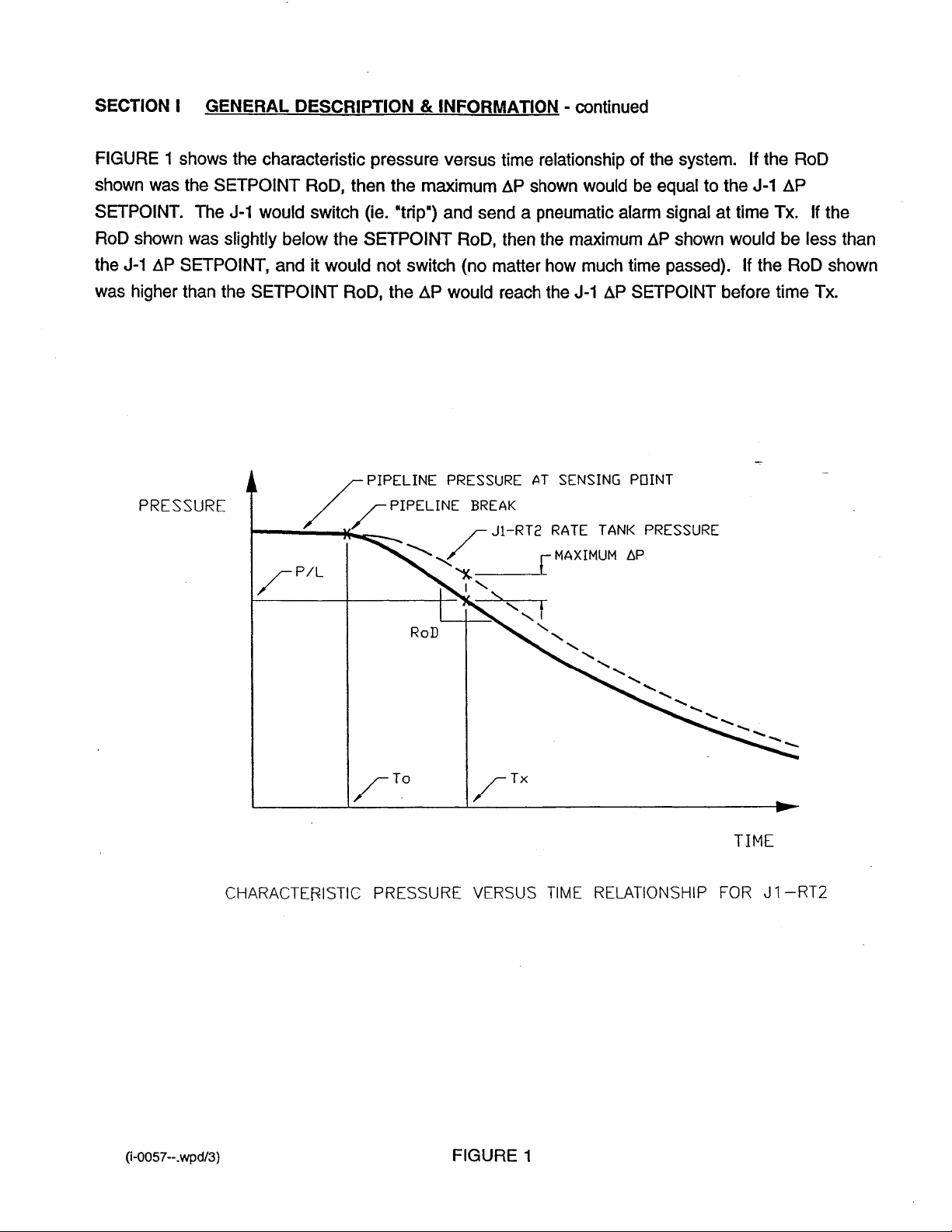
The Bettis J1-RT2 system is designed to automatically monitor a gas pipeline, and deliver a
pneumatic signal if a pre-determined rate of pressure drop is exceeded. The unit is typically
used to detect a pipeline break situation and signal a valve operator.
The system consists of a rate tank, J-1 differential pressure pilot, restrictor, check valve,
manifold assembly and associated tube, fittings, gauges and filters.
The system works as follows: when pipeline pressure is rising, gas flows through the check
valve and restrictor, into the rate tank. When pipeline pressure is falling, gas flows out of the
rate tank, back to the pipeline through the restrictor only. The restrictor resists the flow creating
a pressure drop which is sensed by the J-1 as differential pressure. The J-1 will send a
pneumatic signal if the differential pressure exceeds its calibrated setting. The greater the rate
of drop in the pipeline pressure, the greater the differential pressure across the J-1. The
following abbreviations will be used:
pipeline pressure P/L
rate of drop RoD
differential pressure ∆P
Normally, the pipeline will be operating at a steady or slowly changing pressure. When a
pipeline break occurs, the RoD at the J1-RT2 sensing point will depend on the distance to the
break. Greater distance to the break will decrease RoD at the sensing point. A compromise
must be made in adjusting the RoD setpoint. It must be as low as possible to detect remote
breaks, but not so low that normal pipeline pressure fluctuations will cause a false alarm.
As indicated earlier, the J-1 differential pressure pilot does not respond directly to RoD but to
∆P. The ∆P depends on RoD, but also on:
1. P/L: The RoD required to generate a given ∆P increases with higher P/L.
2. Time: After the initiation of a RoD due to a pipeline break the ∆P takes time to reach its
maximum value.
These dependencies are inherent in this type of system. The time delay in reaching the
maximum ∆P necessitates the following clarification:
P/L is the pipeline pressure occurring at the time that the maximum ∆P is developed, not the
pipeline pressure at the initiation of the RoD (refer to FIG 1). This time delay is apparent
and accounted for in the FUNCTION CHECK procedure (SECTION IV).
(i-0057--.wpd/2)

SECTION I GENERAL DESCRIPTION & INFORMATION - continued
Each combination of restrictor and rate tank size has a specific CALIBRATION CHART (Refer
to FIG 6), identified by a TYPE number which corresponds to the TYPE number stamped on
the unit name plate.
The CALIBRATION CHART maps the relationship between ∆P, RoD and P/L. The J-1 pilot is
calibrated to trip at a particular ∆P by adjusting the spring preload or changing springs. The
CALIBRATION CHART also indicates the ∆P ranges of the four J-1 springs which may be used
(stocked at the factory). The selection of restrictor is done at the factory based on the specified
RoD range and P/L operating range. Specific instructions for reading the required ∆P from the
CALIBRATION CHART are given in Section III (4. J-1 ∆P CALIBRATION).
The CALIBRATION CHARTS are for natural gas with a specific gravity (SG) of .67 and
temperature of 20bC. After correcting for SG and temperature, they will normally agree with
field data within ±20% (on RoD). The inaccuracy is due to manufacturing tolerances and the
fact that the chart P/L lines are adjusted from original data using air. Considering the above,
the recommended uses of the CALIBRATION CHARTS are limited to the following:
- Selection of the correct restrictor for an application (normally done at the factory).
- Initial J-1 pilot calibration (normally done at the factory), to be verified at final installation
using the FUNCTION CHECK procedure (Section IV).
- Illustration of performance characteristics for training, calibration or troubleshooting
purposes.
Use of the CALIBRATION CHARTS to verify FUNCTION CHECK data is not recommended as
it is complicated, (Corrections would generally have to be made for SG and temperature) and
unnecessary, (the data from the FUNCTION CHECK procedure, stands by itself as proof that
the system is operating to specification, provided the unit has been calibrated and tested per
Section III).
It is recommended that users establish their own baseline calibration records using the
procedures in Section III and IV and keep calibration records.
(i-0057--.wpd/4)

SECTION II INSTALLATION AND START-UP
GENERAL INFORMATION
The unit can be installed remote from or on the valve operator. The following preparations
are required:
1. Ensure the isolation valve on the pipeline is installed with take-off to top of pipeline to
allow liquids to drain back into the line.
2. Ensure that pipe and tube to be used is free of chips and debris.
3. Use minimum 1/4 NPT or 3/8 tube, with support adequate to prevent vibration and strain
on connections.
An additional pre-filter is recommended (Refer to Section VI, item 4). It should be installed
between the PIPELINE ISOLATION VALVE (FIG 4, item 101), and the customer supplied
isolation valve at the pipeline take-off.
CONNECTIONS (Refer to FIG 3)
When the J1-RT2 System is shipped pre-installed on the valve operator, customer
connections consist of:
- High pressure pipeline gas connection to PIPELINE ISOLATION VALVE (pipeline
connection "A", ¼ NPT female).
When the J1-RT2 System is shipped separately, customer connections, in addition to
above, include:
- Low pressure supply connection to J-1 pilot valve (supply connection "C", ¼ NPT
female, 150 psig max).
- Low pressure signal connection to J-1 pilot valve (signal connection "B", ¼ NPT female).
(i-0057--.wpd/5)

SECTION II INSTALLATION AND START-UP - continued
START UP (Refer to FIG 4)
1. OPERATION AND FUNCTION OF MANUAL VALVES
a. PIPELINE ISOLATION VALVE (item 101): This valve is normally open. Closing this
valve isolates the system from the pipeline.
b. RATE TANK DRAIN VALVE (item 107): This valve is normally closed and plugged.
Unplug and open to depressurize the J1-RT2 system or drain condensate.
2. START-UP
a. Check and close all manual control valves.
b. Open the main isolation valve on the pipeline (customer supplied).
c. SLOWLY open PIPELINE ISOLATION VALVE (item 101) to pressurize system.
d. When flow into the RATE TANK has stopped, the signal pressure gauge should
indicate if a signal is being applied to (or removed from) the valve operator control
package.
e. The Line Valve (item 2) should be able to be opened and it should remain open.
LEAK TEST ALL FITTINGS AND CONNECTIONS WITH SOAPY WATER.
(i-0057--.wpd/6)

SECTION III CALIBRATION AND TESTING
THREE REQUIREMENTS FOR CORRECT J1-RT2 OPERATION:
CORRECT J-1 PILOT CALIBRATION:
Verify using the J-1 ∆P CALIBRATION procedure in this section.
LEAK-TIGHT HIGH PRESSURE SIDE:
Verify using the PRESSURE HOLD TEST procedure in this section.
UNOBSTRUCTED RESTRICTOR AND FILTERS:
Verify using the PLUGGING TEST procedure in this section.
CALIBRATION AND TESTING PROCEDURES:
For routine calibration and testing, the following steps (1 to 7) are to be executed in
sequence.
NOTE: THESE PROCEDURES REQUIRE BETTIS CALIBRATION KIT, PART NO. 930-
980. REFER TO APPENDIX A FOR AN ALTERNATE PROCEDURE BASED
ON SIMPLIFIED EQUIPMENT. THIS SIMPLIFIED EQUIPMENT IS SPECIFIED
IN THE PROCEDURE AND MAY BE SUPPLIED BY THE USER.
1. DISARM SYSTEM
Isolate or disarm controls and equipment downstream of the J1-RT2 output signal to
prevent inadvertent operation or alarms (Follow applicable procedures and operating
instructions). Depending on where and how this is done, selected downstream controls
can be left active. The function of these controls can then be verified when J1-RT2
output signals are generated during the following procedures.
2. CHECK FOR EXTERNAL LEAKS:
While the J1-RT2 system is still pressurized, check for external leaks at all connections
using soapy water. Fix any leaks before proceeding.
(i-0057--.wpd/7)

SECTION III CALIBRATION AND TESTING - continued
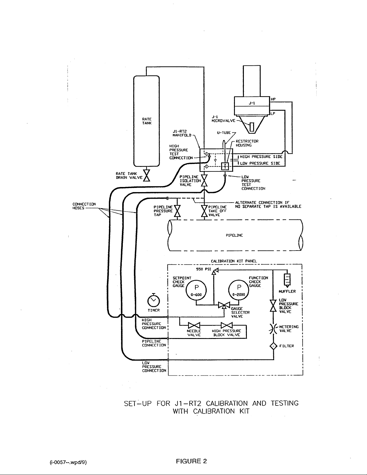
3. SETUP TEST EQUIPMENT
SEE FIG 2, "SETUP FOR J1-RT2 CALIBRATION AND TESTING WITH CALIBRATION
KIT"
CAUTION: DISARM AND DEPRESSURIZE BEFORE ATTEMPTING SERVICE; Close
the PIPELINE TAKE-OFF VALVE and de-pressurize the system by opening
the RATE TANK DRAIN VALVE.
CAUTION: Ensure that contaminants (eg. dust, soapy water, etc.) do not enter at the
HIGH or LOW PRESSURE TEST CONNECTIONS.
a. Connect HIGH PRESSURE CONNECTION on CALIBRATION KIT PANEL to HIGH
PRESSURE TEST CONNECTION on the J1-RT2 MANIFOLD (3/8 tube fitting).
b. Connect LOW PRESSURE CONNECTION on CALIBRATION KIT PANEL to LOW
PRESSURE TEST CONNECTION on the J1-RT2 MANIFOLD (1/4 tube fitting).
c. Connect PIPELINE CONNECTION on CALIBRATION KIT PANEL to a PIPELINE
PRESSURE TAP (or between the PIPELINE TAKE-OFF VALVE and the PIPELINE
ISOLATION VALVE).
Ensure: 1. All CALIBRATION KIT PANEL valves are closed except the METERING
VALVE which should be near fully open.
2. GAUGE SELECTOR VALVE is set to FUNCTION CHECK.
3. All connections are made leak tight.
To pressurize system for leak checking connections:
- Open PIPELINE TAKE OFF VALVE and PIPELINE ISOLATION VALVE
- Open HIGH PRESSURE BLOCK VALVE
- Slowly open CALIBRATION PANEL NEEDLE VALVE allowing system to fill and
stabilize
To vent off:
- Close PIPELINE TAKE OFF VALVE
- Open RATE TANK DRAIN VALVE
- Open LOW PRESSURE BLOCK VALVE
(i-0057--.wpd/8)

SECTION III CALIBRATION AND TESTING - continued
4. J-1 ∆P CALIBRATION
a. Remove U-TUBE and install caps on fittings.
b. Open the LOW PRESSURE SIDE to atmosphere by fully opening the METERING
VALVE and the LOW PRESSURE BLOCK VALVE. Close the RATE TANK DRAIN
VALVE and PANEL NEEDLE VALVE. Set the GAUGE SELECTOR VALVE to the
SETPOINT CHECK GAUGE.
c. Open the HIGH PRESSURE BLOCK VALVE and slowly increase pressure on the
HIGH PRESSURE SIDE using the NEEDLE VALVE. Note the reading on the
SETPOINT CHECK GAUGE when the J-1 switches (ie. MICROVALVE toggles).
Close NEEDLE VALVE after J-1 switches.
d. Repeat test, vent the HIGH PRESSURE SIDE by closing the NEEDLE VALVE and
opening the RATE TANK DRAIN VALVE, and repeat procedure b and c above.
e. Compare the J-1 switch pressure to the required ∆P*.
f. Adjust the J-1 spring load if required (turn adjusting nut FIG 4, item 111) and repeat
steps b, c and d until switching occurs at the required ∆P. If the required ∆P is
outside the range of the J-1 spring, contact the factory for an alternate.
* If the required ∆P is unknown or not yet established, use the CALIBRATION CHART to
find the ∆P corresponding to the specified/desired rate-of-drop (RoD) and pipeline
pressure (P/L). (If the pipeline operates over a wide pressure range, a typical pressure
must be selected).
Use of CALIBRATION CHART to find ∆P: Find the specified/desired RoD along the
horizontal axis and trace a line upward to where it intersects the specified/desired P/L
line (interpolation between P/L lines may be required). From this intersection trace a
horizontal line to the vertical axis and read the ∆P value. Refer to comments on the
CALIBRATION CHART in Section I.
(i-0057--.wpd/10)

SECTION III CALIBRATION AND TESTING - continued
5. PRESSURE HOLD TEST
a. Ensure the PIPELINE ISOLATION VALVE is closed. Depressurize the system by
venting the RATE TANK (open the RATE TANK DRAIN VALVE). Disconnect the
hose from the PIPELINE PRESSURE TAP and PANEL PIPELINE CONNECTION.
Re-install plugs at both fittings.
b. If not done in step 4a then, remove the U-TUBE and install tubing caps on the
fittings. CAUTION: Ensure that contaminants (eg. dust, soapy water etc.) do not
enter at these fittings. Close the RATE TANK DRAIN VALVE and HIGH PRESSURE
BLOCK VALVE. CAUTION: Ensure that plugs have been installed leak tight. Check
with soapy water when the system is pressurized in step c. Set the GAUGE
SELECTOR VALVE to the SETPOINT CHECK GAUGE.
c. LOW PRESSURE HOLD TEST: Close the LOW PRESSURE BLOCK VALVE.
Pressurize the HIGH PRESSURE SIDE to 20 psi by opening the PIPELINE
ISOLATION VALVE (the flow through the check valve will require it to open and
reseat at low pressure resulting in a worst case test). Stabilize the pressure reading
for one minute then vent the LOW PRESSURE SIDE by opening the LOW
PRESSURE BLOCK VALVE (METERING VALVE near fully open). Monitor the
SETPOINT CHECK GAUGE for 3 minutes. The maximum allowable pressure loss is
10% of RoD over 3 minutes (eg. if RoD = 20 psi/min then allowable pressure loss
over 3 minutes is 2 psi or less).
d. HIGH PRESSURE HOLD TEST: Close the LOW PRESSURE BLOCK VALVE.
Pressurize the HIGH PRESSURE SIDE to 500 psi (or to available P/L if less) by
opening the PIPELINE ISOLATION VALVE. Stabilize the pressure reading for one
minute then vent the LOW PRESSURE SIDE by opening the LOW PRESSURE
BLOCK VALVE and metering valve is nearly full open. Monitor the SETPOINT
CHECK GAUGE for 3 minutes. The maximum allowable pressure loss is 10% of
RoD over 3 minutes (see example in step c above).
(i-0057--.wpd/11)

SECTION III CALIBRATION AND TESTING - continued
e. If the maximum allowable pressure loss rates are exceeded, there is a leak in the
HIGH PRESSURE SIDE which must be traced and fixed. A failure of the LOW
PRESSURE HOLD TEST is likely due to a faulty check valve. A failure of the HIGH
PRESSURE HOLD TEST is likely due to leaking tube fittings, valves or internal
leakage through the J-1 diaphragm or the check valve (refer to Section VI,
MAINTENANCE PROCEDURES). Depressurize the system by venting the RATE
TANK (open the RATE TANK DRAIN VALVE).
6. PLUGGING TEST
a. Ensure the PIPELINE ISOLATION VALVE is closed and the system is depressurized
(ie. the RATE TANK DRAIN VALVE is open).
b. Re-install the U-TUBE. Ensure that these tube connections are leak tight as they are
on the HIGH PRESSURE SIDE. Check with soapy water after the system is
pressurized. CAUTION: Use minimal torque when remaking U-TUBE connections to
extend tube life.
c. Close the RATE TANK DRAIN VALVE and LOW PRESSURE BLOCK VALVE.
Ensure the METERING VALVE is near fully open, the HIGH PRESSURE BLOCK
VALVE is closed and the GAUGE SELECTOR VALVE is on SETPOINT CHECK
GAUGE.
d. Pressurize the system to 300 psi by opening the PIPELINE ISOLATION VALVE.
Stabilize the pressure for one minute (If pressure will not stabilize, there is a leak in
the system which must be fixed before running the test. See item 5, PRESSURE
HOLD TEST).
e. Open the LOW PRESSURE BLOCK VALVE and simultaneously start TIMER.
f. Record pressure reading at 90 seconds and close the LOW PRESSURE BLOCK
VALVE.
g. Compare this to the appropriate MAXIMUM END PRESSURE value in the table
below. If the end pressure is above the maximum, there is plugging or obstruction of
the restrictor or filters (refer to Section VI, MAINTENANCE PROCEDURES).
(i-0057--.wpd/12)
 Loading...