

Manual: Installation, Operation and Maintenance Q-Series - Release 2 - 2019 | Bettis
Table of contents
 Loading...
Bettis Manual: Installation, Operation and Maintenance Q-Series - Release 2 - 2019 | Bettis Manuals & Guides
Installation, Operation and Maintenance Manual
Bettis Q-Series
Pneumatic Actuators with Integrated Controls
DOC.IOM.BQ.E Rev. 3
April 2019


Installation, Operation and Maintenance Manual
DOC.IOM.BQ.E Rev. 3
Table of Contents
Section 1: Before You Start
1.1 Installation, Operation and Maintenance Reference Documents .................... 1
1.2 Warehouse Storage ....................................................................................... 2
1.3 On-Site Storage ............................................................................................. 2
Section 2: Introduction
2.1 Identication ................................................................................................. 3
2.2 Intended Use .................................................................................................5
2.3 Specications ................................................................................................ 5
Section 3: Configuration Code
Table of Contents
April 2019
Section 4: Installation
4.1 Before You Start ............................................................................................ 9
4.2 Actuator Rotation Direction .......................................................................... 9
4.2.1 Valve Rotation .................................................................................... 9
4.2.2 Position After Failure ........................................................................ 10
4.3 Principles of Operation ................................................................................ 11
4.3.1 Pneumatic Operation of the Base Actuator ....................................... 11
4.3.2 Ingress Protection (IP) Rating ........................................................... 12
4.3.3 Control Module Operation................................................................12
4.3.4 Double-Acting Operation with Fail-In-Last Position Function ............ 14
4.3.5 Spring-Return Actuators ................................................................... 16
4.3.6 Position Feedback ............................................................................ 18
4.4 Actuator Assembly Codes ........................................................................... 19
4.5 Actuator to Valve Installation ...................................................................... 21
4.6 Mounting of Control Modules or Generic Control and Feedback Accessories .... 24
4.7 Recommended Tubing Sizes ........................................................................ 24
Section 5: Mechanical Stroke Adjustment
5.1 Travel Stop Adjustment ............................................................................... 26
5.1.1 Double-Acting Actuators .................................................................. 26
5.1.2 Spring-Return Actuators ................................................................... 27
5.1.3 Angular Displacement ...................................................................... 28
Section 6: Maintenance
6.1 Normal Maintenance ................................................................................... 29
6.2 Inspection and Repair .................................................................................. 30
6.2.1 Service Kits ....................................................................................... 30
6.2.2 Spring-Return Actuator .................................................................... 30
Section 7: Decommission (Out of Service)
7.1 Before You Start .......................................................................................... 31
7.2 Removing the Actuator from the Valve ........................................................ 32
ITable of Contents

Table of Contents
April 2019
Section 8: Disassembly
Section 9: Reassembly
Installation, Operation and Maintenance Manual
DOC.IOM.BQ.E Rev. 3
8.1 Removing End Caps (Size 40 to 600)............................................................ 34
8.2 Removing End Caps (Size 950 to 1600) ....................................................... 36
8.3 Removing Spring Cartridges or Springs ....................................................... 37
8.4 Removing of Limit Stop Screws ................................................................... 38
8.5 Removing Pistons ........................................................................................38
8.6 Removing Pinion ......................................................................................... 39
8.7 Cleaning the Components .......................................................................... 40
9.1 Grease Instructions ..................................................................................... 42
9.2 Reassembly of the Pinion ............................................................................. 43
9.3 Reassembly of the Pistons ........................................................................... 44
9.4 Reassembly and Settings of the Limit Stops ................................................. 46
9.5 Reassembly of the End Caps ........................................................................ 47
9.5.1 Double-Acting Actuators .................................................................. 47
9.5.2 Spring-Return Actuators (Size 40 to 600) ..........................................48
9.5.3 Spring-Return Actuators (Size 950 to 1600) ......................................50
9.6 Basic Function and Air Leak Test .................................................................. 52
Section 10: Troubleshooting
10.1 Mechanical Problems .................................................................................. 53
10.2 Pneumatic Problems ................................................................................... 54
10.3 Electrical Problems ...................................................................................... 55
Section 11: Parts List and Spare Parts Recommendations
11.1 Actuator Size Q40 to Q600 .......................................................................... 56
11.2 Actuator Size Q950 to Q1600 ...................................................................... 57
Appendix A: Spring Load Removal
A.1 Spring Load Relief ........................................................................................ 58
Appendix B: Tool & Torque Table
Appendix C: Full Stroke Adjustment Option
C.1 Full Stroke Adjustment Option .................................................................... 62
C.2 Convert a Standard Actuator into a Full Stroke Adjustment Version ............. 63
11.2.1 Procedure ........................................................................................64
C.3 Full Stroke Adjustment Setting .................................................................... 65
11.2.2 Factory Setting Procedure ................................................................ 65
11.2.3 Setting the Full Stroke Adjustment Screw to the Required Angle....... 66
II
Table of Contents

Installation, Operation and Maintenance Manual
DOC.IOM.BQ.E Rev. 3
Section 1: Before You Start
This section explains:
• Base safety procedures.
• Where to nd detailed information relating safety.
• Storage guidelines.
Installation, adjustment, putting into service, use, assembly, disassembly and maintenance
of the pneumatic actuator must be performed by qualied personnel.
NOTICE
Failure to follow the above guidelines will void warranty.
WARNING
Section 1: Before You Start
April 2019
Actuator must be isolated both pneumatically and electrically before any (dis)assembly starts.
Before mounting or (dis)assembly, the actuator consult the relevant sections of this manual.
1.1 Installation, Operation and Maintenance Reference Documents
Before you start, read the following documents:
• All Sections in this manual.
• Safety Guide (Document No. DOC.SG.BQ.EN).
Mounted Control modules are shipped with the applicable installation guide:
QC41, QC42 or QC43: Document DOC.IG.BQC41.1.
QC40: Document DOC.IG.BQC40.1.
QC54: Document DOC.IG.BQC54.1.
For Safety Instrumented Systems application, read the following document:
• SIL Safety Manual Bettis Q-Series (Document No. DOC.SILM.BQ.EN).
Before You Start
NOTICE
Failure to read the Safety Guide will void the warranty.
Not following the instructions of the Safety Guide can lead to failure of the product and
harm to personnel or equipment.
1

Section 1: Before You Start
April 2019
Installation, Operation and Maintenance Manual
1.2 Warehouse Storage
• All actuators should be stored in a clean, dry warehouse, free from excessive
vibration and rapid temperature changes.
• All actuators should not be stored directly to the oor surface - it must be placed in
racks/shelves or use a pallet.
1.3 On-Site Storage
• All actuators should be stored in a clean, dry warehouse, free from excessive
vibration and rapid temperature changes.
• Prevent moisture or dirt from entering the actuator. Plug or seal both air
connection ports.
NOTICE
Failure to follow the above guidelines (Warehouse and On Site Storages) will void warranty.
DOC.IOM.BQ.E Rev. 3
Before You Start2

Installation, Operation and Maintenance Manual
DOC.IOM.BQ.E Rev. 3
Section 2: Introduction
This section explains:
• How to identify the received product.
• The intended use of the product.
• Construction details.
• Actuator specications.
2.1 Identification
The Bettis Q-Series Rack and Pinion actuators are available as double-acting or springreturn versions. 9 models are available, ranging from 40 Nm to 1600 Nm (354 to 14161 lbf.
in) nominal torque output.
The Bettis Q-Series package consists of an actuator with a module for control and position
feed back and forms an integrated concept for “On/Off” valve automation.
Section 2: Introduction
April 2019
1. Basic Actuators
The basic actuator supplies the torque, required to open and close valves and is
available in various sizes (rated 47 to 1676Nm at 5.5barg or 413 to 14874 In.lb. at 80pisg).
Double acting and spring return executions are available. The spring return execution can be
equipped with multiple spring sets to cover a pressure range from 2 to 8 barg (30 to 120 psig).
The springs in the spring-return version allow a fail action in case of loss of air supply
pressure (Fail-to-Close or Fail-to-Open). As from size FD150 double-acting versions have
at end caps to reduce actuator length and internal air volume.
The springs in the spring-return version allow a fail action in case of loss of air supply
pressure (Fail-to-Close or Fail-to-Open).
As from size 150 double-acting versions have at end caps to reduce actuator length and
internal air volume.
2. Control Modules
The Control Modules contain, next to the components for feedback switches, also all the
pneumatic control components.
Its compact and robust construction incorporates basic control and feedback functionality
and is suitable for indoor and outdoor use.
Introduction
3

Section 2: Introduction
e
April 2019
Figure 1 Identification
Installation, Operation and Maintenance Manual
DOC.IOM.BQ.E Rev. 3
1
2
3 4
Size End cap design
SR DA
5
Spring design
Left
6
Right
Pinion bottom /
Insert design
2
40 100
Maximum 12
spring cartridges
SR Left RightDA
150 -
600
Maximum 12
spring cartridges
Left RightSR DA
950 -
1600
Notes:
1. Top auxilliaries according (VDI/VDE 3845; NAMUR). Bettis Q-Series comes with a proprietary pneumatic
interface for direct mounting of the Control modules.
2. Valve interface available according ISO5211 or DIN 3337. Actuator sizes 40 to 1600 can be fitted with driv
inserts with various inner shapes.
3. Spring-Return actuators: - with springs
4. Double-Acting actuators: - no springs
5. Actuator sizes 40 to 100 have high end caps for double-acting and spring-return models. Actuator sizes
150 to 1600 have low end caps for double-acting models and high end caps for spring-return models.
6. Actuator sizes 40 to 600 are fitted with a maximum of 12 spring cartridges. Actuator sizes 950 and 1600
are fitted with a maximum of 6 loose springs.
Maximum 6
loose springs
Introduction4

Installation, Operation and Maintenance Manual
DOC.IOM.BQ.E Rev. 3
2.2 Intended Use
The Bettis Q-Series Rack and Pinion actuators are intended for the automation and
operation of quarter-turn valves like Buttery, Ball and Plug valves.
Rack and Pinion actuators can also be used to operate dampers or any other quarter-turn
applications.
2.3 Specifications
Table 1. Pressure Range
Actuator Type Pressure
Double-Acting 0.2 to 8.3 barg (2.9 to 120 psig)
Spring-Return
6 to 8.3 barg (87 to 120 psig), with maximum spring set
3 to 8.3 barg (43.5 to 120 psig), reduced spring quantity
Section 2: Introduction
April 2019
Table 2. Operating Media
Actuator Type Operating Media
Air, dry or lubricated and inert gases
Dew point at least 10K below ambient temperature
Double-Acting and Single-Acting
1. For the base actuator the recommended air quality for normal operation
(according ISO 8573-1) is: 7-5-4.
2. In case Q-Series Control Modules are used, the operating media specication as mentioned in
the Installation Guide (shipped with each control module) are applicable.
QC41, QC42 or QC43: Document DOC.IG.BQC41.1.
QC40: Document DOC.IG.BQC40.1.
QC54: Document DOC.IG.BQC54.1.
For sub-zero applications, take appropriate measures
Mentioned pressure levels are "gauge pressures".
Gauge pressure is equal to absolute pressure minus
atmospheric pressure.
NOTE:
Use of lters, pressure regulators, lubricator and an oil/water separator mounted in the air
supply line, will allow a smooth and durable operation of the actuator.
For lubricated supply air, it is recommended to use a non-detergent oil without aggressive
additives, VG32, group 2 (ISO 3448).
Table 3. Temperature Range
Introduction
Actuator Type Temperature
Standard -20°C to +80°C (-4°F to +176°F)
1. In case Q-Series Control Modules are used, the temperature range as mentioned in
the Installation Guide (shipped with each control module) are applicable.
QC41, QC42 or QC43: Document DOC.IG.BQC41.1.
QC40: Document DOC.IG.BQC40.1.
QC54: Document DOC.IG.BQC54.1.
5

A
B
Section 2: Introduction
April 2019
Table 4. Air Volumes and Consumption
Actuator
model
Q 0040 0.26 0.37 0.15 0.67 1.2 2.2 0.89 1.6 3.1
Q 0065 0.40 0.56 0.22 1.02 1.8 3.4 1.3 2.4 4.7
Q 0100 0.6 0.9 0.3 1.5 2.7 5.0 2.0 3.8 7.2
Q 0150 1.0 0.8 0.5 2.4 4.3 8.1 2.1 3.6 6.7
Q 0200 1.3 1.0 0.7 3.2 5.7 11 2.8 4.9 9.1
Q 0350 2.1 1.9 1.2 5.5 9.8 18 5.0 8.8 16
Q 0600 3.6 3.3 2.1 9.4 17 31 8.7 15 28
Q 0950 4.9 4.6 3.2 13 23 43 12 22 40
Q 1600 7.9 7.3 5.4 21 37 69 20 35 64
Installation, Operation and Maintenance Manual
DOC.IOM.BQ.E Rev. 3
Actuator volumes:
Maximum volume (in liters) Outward Stroke Inward Stroke
Double-Acting
and Spring-Return
2.0 barg 4.0 barg 8.0 barg 2.0 barg 4.0 barg 8.0 barg
Central
chamber
1
End cap
chamber
2
Displaced
volume
3
Consumption per stoke
(in liters, pressure in barg)
Double-Acting only
Actuator volumes:
Maximum volume (Cu.in.) Outward Stroke Inward Stroke
Actuator
model
Q 0040 15.9 23 8.9 53 96 140 71 133 196
Q 0065 24 34 13.5 81 148 215 107 200 294
Q 0100 36 53 19.9 118 216 314 165 310 455
Q 0150 58 47 32 192 352 512 163 293 424
Q 0200 76 64 44 255 466 676 220 397 573
Q 0350 131 115 76 436 796 1157 392 709 1025
Q 0600 222 201 129 742 1354 1967 683 1237 1790
Q 0950 301 279 196 1025 1854 2682 966 1735 2505
Q 1600 484 447 328 1662 2997 4331 1560 2792 4024
Central
chamber
1
End cap
chamber
2
Displaced
volume
3
Double-Acting
and Spring-Return
40 psig 80 psig 120 psig 40 psig 80 psig 120 psig
Consumption per stoke
(in Cu.in., pressure in psig)
Double-Acting only
Notes:
1. Pistons at 90° outward position.
2. Pistons at 0° inward position.
3. Stroke is 90°.
Figure 2 Actuator Air Volumes
Central air chamber volume
Double-Acting and Spring-Return
End cap air chamber volume
Double-Acting only
6
Introduction
Installation, Operation and Maintenance Manual
DOC.IOM.BQ.E Rev. 3
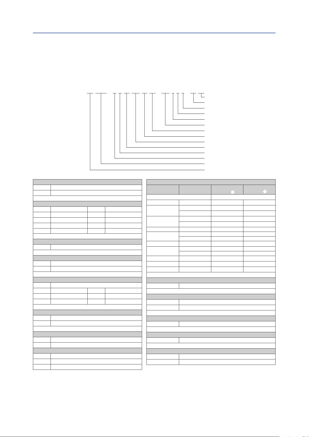
Section 3: Conguration Code
This section explains:
• How to create or read the conguration code for a actuator.
QS 0150 - N U 40 CW AL TN - L17 S K B - 00 XX
Section 3: Configuration Code
April 2019
Miscellaneous options
Internal code 1
Color / nish
Visual indicator
Temperature
Valve stem connection
Valve interface
Pinion material
Rotation
Spring set
Threads
Rotation angle
Size
Typ e
Typ e
FD Double Acting
FS Spring Return
Size
0040 Size 0040 0350 Size 0350
0065 Size 0065 0600 Size 0600
0100 Size 0100 0950 Size 0950
0150 Size 0150 1600 Size 1600
0200 Size 0200
Rotation Angle
N 90° rotation angle
Threads
M Metric ISO 5211
U UNC/NPT/Imperial
Spring Set
00 Double Acting (no springs)
10 Spring Set 10 40 Spring Set 40
20 Spring Set 20 50 Spring Set 50
30 Spring Set 30 60 Spring Set 60
Rotation Direction
CW Spring to Close/Clock Wise
CC Spring to Open/Counter Clock Wise
Valve Stem Connection, Note 3
Actuator Size
No insert 000
0040 & 0065 14mm / 0.551" L14 D14
0100
0150
0200 22mm / 0.866" L22 D22
0350
0600 27mm / 1.063" L22 D22
0350
0600 27mm / 1.063" L27 D27
0950 36mm / 1.417" L36 D36
1600 46mm / 1.811" L46 D46
Temperature Range
S Standard: -20°C to +80°C (-4°F to +176°F)
Visual Indication Code
K Standard (Knob)
N No Visual Indication
Finish
B Standard coating (Bettis Orange)
Square
Dimensions
17mm / 0.669" D17
19mm / 0.748" L19
17mm / 0.669" D17
19mm / 0.748" L19
22mm / 0.866" D22
27mm / 1.063" L27
22mm / 0.866" D22
27mm / 1.063" L27
Parallel
Drive
Diagonal
Drive
Pinion Material
AL High Grade Aluminium, Hard anodized
Valve Interface, Note 2
TN Standard ISO 5211 interface
SY Small interface with center plate (DIN3337)
LY Large interface with center plate (DIN3337)
Notes:
See next page.
Conguration Code
Internal Code 1
00 Standard
Miscellaneous Options
XX Standard: Suitable for Control module mounting
FS Full stroke adjustement (only sizes 40 to 600)
7

Section 3: Configuration Code
April 2019
Notes:
1. The options, listed here, are all options available. Not all options apply to all
congurations. Check the actuator size page for valid congurations.
2. Valve Interface:
— Option "S"; Small Interface with Center Plate (DIN3337)
— Option "L"; Large Interface with Center Plate (DIN33337)
3. Contact your local Bettis Q-Series representative for additional insert options.
4. PED Group 1 Label only available up to size 950.
Installation, Operation and Maintenance Manual
DOC.IOM.BQ.E Rev. 3
is not available for sizes 0950.
is not available for sizes 1600.
8
Conguration Code

Installation, Operation and Maintenance Manual
DOC.IOM.BQ.E Rev. 3
Section 4: Installation
This section explains:
• The actuator rotation direction.
• In which position the actuator will end after a failure.
• Principles of operation:
— Pneumatic operation.
— Double acting and Spring return operation.
• Assembly codes.
• Actuator to valve assembly.
4.1 Before You Start
Section 4: Installation
April 2019
SAFETY
In case of an air or electrical failure, it is important to know the behavior of the actuator.
Before mounting the actuator on a valve, consult the following sections below.
4.2 Actuator Rotation Direction
4.2.1 Valve Rotation
For the following paragraphs we assume that valves rotate as indicated in Figure 3.
Figure 3 Normal valve rotation
Installation
The valve is closed after
a clockwise rotation.
The valve is open after
a counterclockwise rotation.
9

Section 4: Installation
April 2019
4.2.2 Position After Failure
The position of the actuator after a failure depends on the:
1. Principle of operation (see paragraph 4.3)
2. Assembly codes (see paragraph 4.4)
3. Kind of failure. Refer to the table below.
Table 5. Position After Failure
Installation, Operation and Maintenance Manual
DOC.IOM.BQ.E Rev. 3
Principle of
Operation
Double-Acting
Actuator
Single-Acting
(Spring-Return)
Actuator
Assembly Code Kind of Failure Position
Pressure Not dened
CW
CW
Signal Closed
Supply Voltage Closed
Pressure Not dened
Signal Open
Supply Voltage Open
Pressure Closed
Signal Closed
Supply Voltage Closed
Pressure Open
Signal Open
Supply Voltage Open
Table 6. Position after a failure with a Double-Acting module with
Fail-In-Last-Position Function
Principle of
Operation
Double-Acting
Actuator
Assembly Code Kind of Failure Position
Pressure Not dened
CW
Signal Not dened
Supply Voltage Closed
Pressure Not dened
Signal Not dened
Supply Voltage Open
10
Installation

A
BA
Installation, Operation and Maintenance Manual
DOC.IOM.BQ.E Rev. 3
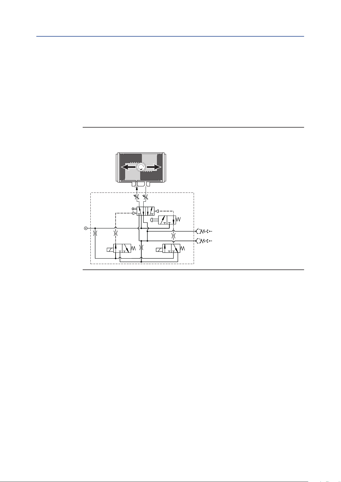
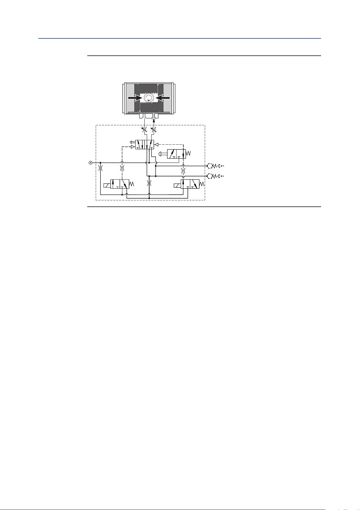
4.3 Principles of Operation
4.3.1 Pneumatic Operation of the Base Actuator
Bettis Q-Series actuator are intended to be operated by the Q-Series Control Modules. For more
details see section 4.3.3. Below gure shows the basic pneumatic operation of the actuator.
Figure 4 Typical Pneumatic Operation
Spring-Return Operation Double-Acting Operation
Section 4: Installation
April 2019
The table below represents the cycle time (operating time) per different Actuator sizes:
Table 7. Operating Speed
Cycle time in seconds
Actuator
size
Q 40 0.6 0.5 0.6 0.5
Q 65 0.7 0.5 0.6 0.6
Q 100 0.8 0.6 0.8 0.7
Q 150 1.0 0.8 0.9 0.8
Q 200 1.3 0.9 1.0 1.0
Q 350 1.9 1.3 1.4 1.5
Q 600
Q 950 6.6 2.2 2.4 2.0
Q 1600 10.6 3.5 3.6 3.3
Operating time is average with actuator under load and solenoid valve tted.
Test conditions:
1. Solenoid with ow capacity: 0.6 m3/hr
2. Pipe diameter: 6mm
3. Medium: clean air
4. Supply pressure: 5.5 bar (80psi)
5. Load: with average load
6. Stroke: 90°
7. Temperature: Room temperature
pressurized
Spring-Return Double-Acting
A-port
3.2 1.9 2.2 2.2
Spring
stroke
A-port
pressurized
pressurized
B-port
Installation
11

Section 4: Installation
Installation, Operation and Maintenance Manual
April 2019
4.3.2 Ingress Protection (IP) Rating
Bettis Q-Series actuators are IP66 / NEMA4 rated. In case of IP66 or NEMA4 requirements,
take precautions that comply with the IP66 / NEMA4 requirements to prevent moisture or
dust from entering the actuator through the open air exhaust port(s), either directly on the
actuator or at the exhaust ports of the connected solenoid valve.
We recommend to connect tubing to the exhaust(s) and lead this into a dry and dust free
area, or to use check valves in the exhaust.
4.3.3 Control Module Operation
The operating principle, as explained here, is applicable for actuators with assembly code
CW (direct acting).
• The outward stroke will move the valve to the “Open” position.
• The inward stroke will move the valve to the “Closed” position.
• For assembly codes CC, the operating principle is reversed (reverse acting):
DOC.IOM.BQ.E Rev. 3
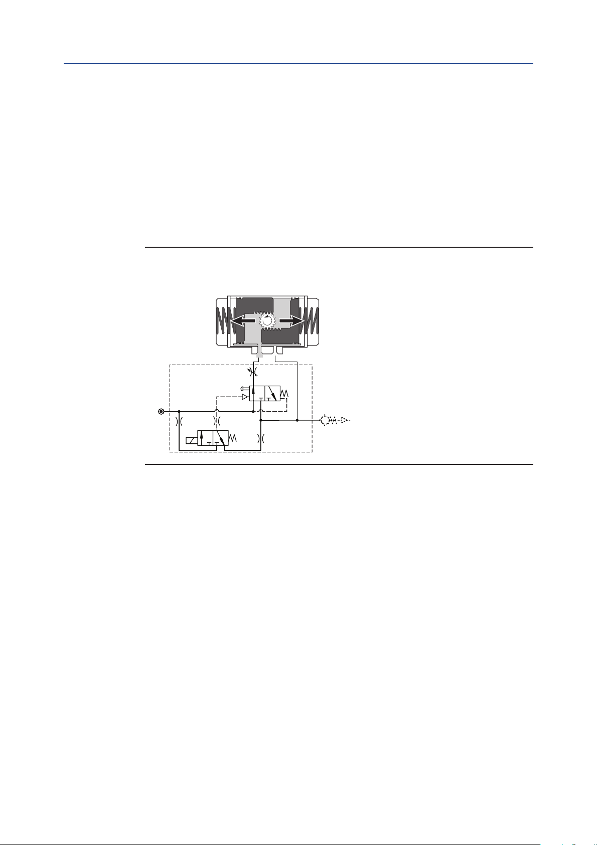
Figure 5 Double-Acting Operation
Outward Stroke
A-port
Option:
Throttle 1
5/2 Spool valve
Option: LMC
Ps
Pilot
valve 1
B-port
Option:
Throttle 2
Rb
Ra
1. Send control signal “Open” to the Control Module.
2. Pilot valve 1 will be activated and the 5/2spool valve will pressurize the central
air chamber.
3. The piston will move outwards to the “Open” position.
4. The Control Module indicates the “Open” position and activates feedback
signal “Open”.
12
Installation

Installation, Operation and Maintenance Manual
DOC.IOM.BQ.E Rev. 3
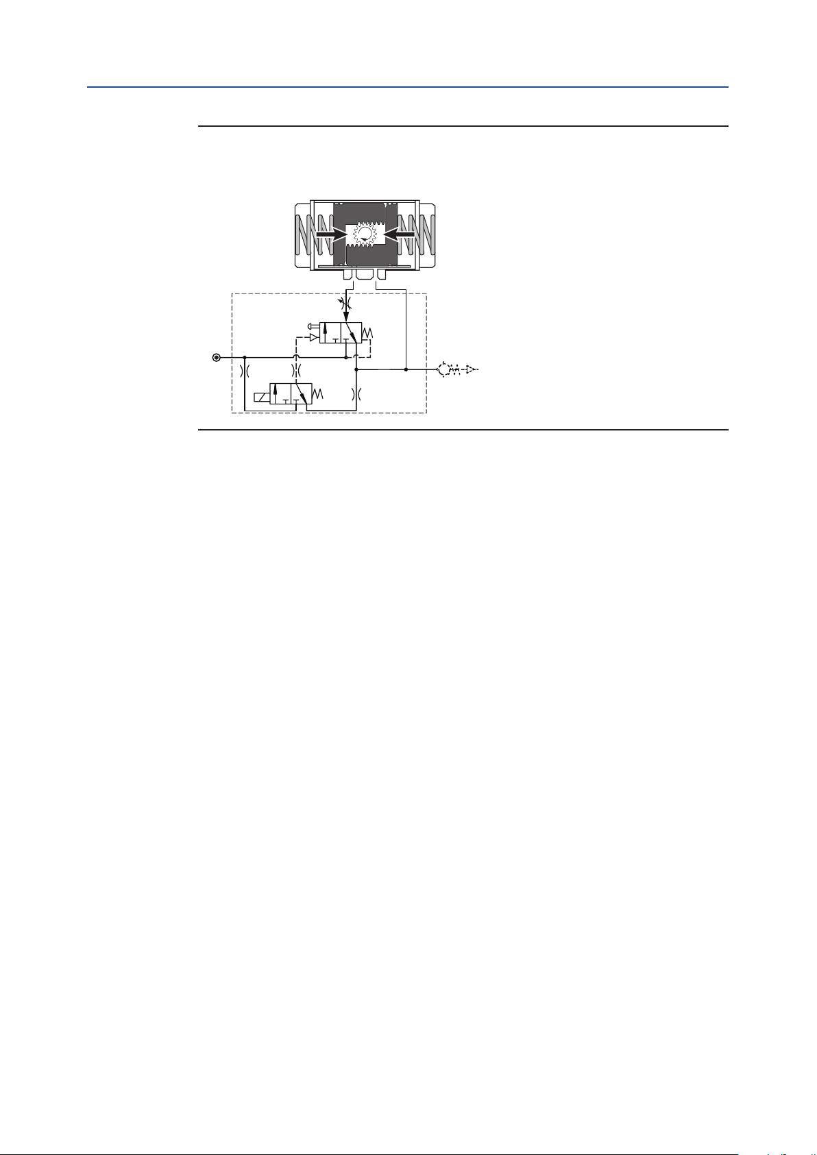
Figure 6 Double-Acting Operation
Inward Stroke
Section 4: Installation
April 2019
A-port
Option:
5/2 Spool valve
Option: LMC
Ps
Pilot
valve 1
Throttle 1
B-port
Option:
Throttle 2
Rb
Ra
1. Send control signal “Close” to the Control Module.
2. Pilot valve 1 will be deactivated and the 5/2 spool valve will pressurize the end cap
air chambers.
3. The piston will move inwards to the “Closed” position.
4. The Control Module indicates the “Closed” position and activates feedback
signal “Closed”.
Optional Controls:
LMC Local Manual Control
SC Speed Control throttles
Important
In case of an electric control signal failure, the actuator will move to its "Closed" position.
Installation
13
Section 4: Installation
April 2019
Installation, Operation and Maintenance Manual
DOC.IOM.BQ.E Rev. 3
4.3.4 Double-Acting Operation with Fail-In-Last Position Function
The operating principle, as explained here, is applicable for actuators with assembly code
CW (direct acting).
• The outward stroke will move the valve to the “Open” position.
• The inward stroke will move the valve to the “Closed” position.
• For assembly codes CC the operating principle is reversed (reverse acting):
Figure 7 Double-Acting Operation with Fail-In-Last Position Function
Outward Stroke
B-port
Option:
Throttle 2
Pilot valve 2
Option:
LMC 2
Rb
Ra
Ps
Option: LMC 1
Pilot valve 1
A-port
Option:
Throttle 1
5/2 Spool valve
1. Send control signal “Open” to the Control Module to activate Pilot valve 1 and
de-activate Pilot valve 2.
2. The 5/2 spool valve will pressurize the central air chamber.
3. The piston will move outwards to the “Open” position.
4. The Control Module indicates the “Open” position and activates feedback
signal “Open”.
14
Installation
Installation, Operation and Maintenance Manual
DOC.IOM.BQ.E Rev. 3
Figure 8 Double-Acting Operation with Fail-In-Last Position Function
Inward Stroke
Section 4: Installation
April 2019
A-port
Option:
Throttle 1
5/2 Spool valve
Option: LMC 1 Option: LMC 2
Ps
Pilot valve 1
B-port
Option:
Throttle 2
Pilot valve 2
Rb
Ra
1. Send control signal “Close” to the Control Module to activate Pilot valve 2 and
de-activate Pilot valve 1.
2. The 5/2 spool valve will pressurize the end cap air chambers.
3. The piston will move inwards to the “Closed” position.
4. The Control Module indicates the “Closed” position and activates feedback
signal “Closed”.
Optional Controls:
LMC Local Manual Control
SC Speed Control throttles
Installation
15
Section 4: Installation
Installation, Operation and Maintenance Manual
April 2019
4.3.5 Spring-Return Actuators
The operating principle, as explained here, is applicable for actuators with assembly code
CW (direct acting).
• Applying supply pressure to port A will move the pistons outwards to the "Open"
position of the valve.
• Venting the supply pressure from port A will cause the springs to move the pistons
inwards to the "Close" position of the valve.
• For assembly codes CC, the operating principle is reversed (reverse acting):
Figure 9 Single-Acting Operation
Outward Stoke
DOC.IOM.BQ.E Rev. 3
A-port
Option: Throttle 1
3/2 Spool valve
Option: LMC
Ps
Pilot
valve 1
B-port
Ra
1. Send control signal “Open” to the Control Module.
2. Pilot valve 1 will be activated and the 3/2 spool valve will pressurize the central
air chamber.
3. The piston will move outwards to the “Open” position.
4. The Control Module indicates the “Open” position and activates feedback
signal “Open”.
16
Installation
Installation, Operation and Maintenance Manual
DOC.IOM.BQ.E Rev. 3
Figure 10 Single-Acting Operation
Inward Stroke
Section 4: Installation
April 2019
A-port
Option: Throttle 1
3/2 Spool valve
Option: LMC
Ps
Pilot
valve 1
B-port
Ra
1. Send control signal “Close” to the Control Module.
2. Pilot valve 1 will be deactivated and the 3/2 spool valve will vent the central
air chamber
3. The springs will move the pistons inwards to the “Closed” position.
4. The Control Module indicates the “Closed” position and activates feedback
signal “Closed”.
Optional Controls:
LMC Local Manual Control
SC Speed Control throttles
Installation
17

Section 4: Installation
April 2019
4.3.6 Position Feedback
The Bettis Q-Series actuator (1) has a patented, contact-less position sensing system.
This system consists of a position probe (2) which is rides on a special curve (4) in the
pinion bottom.
The curve is shaped in such a way that the position probe moves linearly and proportionally
to the rotation of the actuator pinion.
The linear movement of the position probe is used, inside the control module (3) to
operated the limit switches.
CAUTION
Do not put the Control module in direct contact with magnetic material. This can cause
damage or malfunction of the position feedback.
Installation of the Bettis Q-Series Control Modules
Installation, Operation and Maintenance Manual
DOC.IOM.BQ.E Rev. 3
Please refer to the Installation guides, as shipped with the product, for installation
instructions of the Control Module.
Installation Guides - Control modules
Each Control Module is shipped with an Installation Guide, which contains more
information on the pneumatic and electrical installation and operation of the Module.
Additionally, these Installation Guides can be downloaded from: www.emerson.com/bettis
Figure 11
1
3
2
4
18
Installation
Loading...