

Installation, Operation and Maintenance Manual
GVO-LP-SR/FS Spring Return
E-90090003 Rev. A
May 2014


Installation, Operation and Maintenance Manual
E-90090003 Rev. A
Table of Contents
Section 1: Safety Warning
Section 2: Introduction
2.1 General Service Information .......................................................................... 2
2.2 Denition of Terms ........................................................................................ 2
2.3 Scope ............................................................................................................ 3
2.4 Model Identication ...................................................................................... 3
Section 3: Storage Instructions
Section 4: Operation
4.1 SR Operator ................................................................................................... 6
4.2 FS Operator ................................................................................................... 6
Table of Contents
May 2014
Section 5: Preparation
Section 6: Installation
6.1 Notes .......................................................................................................... 11
6.2 Lifting .......................................................................................................... 12
6.3 Procedures of Installation ............................................................................ 13
Section 7: Maintenance
7.1 Regular Maintenance ................................................................................... 17
7.2 Disassembly ................................................................................................ 17
7.3 Inspection and Cleaning .............................................................................. 22
7.4 Reassembly ................................................................................................. 22
Section 8: Operator End Stop Adjustment
8.1 SR - End Stop Adjustment Conditions .......................................................... 27
8.2 FS - End Stop Adjustment Conditions ........................................................... 28
Section 9: Testing and Troubleshooting
9.1 Testing ........................................................................................................ 31
9.2 Troubleshooting .......................................................................................... 31
Section 10: Document Revision ����������������������������������������� 34
Appendix A: List of Tables ���������������������������������������������������35
Appendix B: List of Figures ��������������������������������������������������36
ITable of Contents

Section 1: Safety Warning
May 2014
Installation, Operation and Maintenance Manual
Section 1: Safety Warning
All personnel involved should read and understand all applicable sections of this manual
before attempting to install, operate, service, or perform maintenance on any operators.
Adhere to any tags, warning labels, or instructions present on the operator.
These may provide information more specic and signicant regarding the operator than
this general manual can.
It is the responsibility of the user to ensure proper safety. Always take necessary
precautions and utilize proper personal protective equipment when dealing with
compressed air, compressed hydraulic uid, pinch points, and electricity.
It is necessary to rig and lift valve and operator separately. Service personnel need to
ensure the lifting capacity of the crane/hoist/rigging is appropriate for the desired load.
Block the pressure supply and depressurize the system before attempting to install or
service. Isolate the pressure from controls if the operator is supplied with control system.
Caustic gases and uids may be contained in the operators and valves in most applications.
Vent all poisonous or ammable gases and store all liquids in a safe location to prevent
personnel injury. Discharge at sonic velocity may occur when venting or releasing pressure;
service personnel must utilize proper hearing protection.
E-90090003 Rev. A
CAUTION: DO NOT DISASSEMBLE SPRING CARTRIDGE
Springs are under compression. Do not disassemble any part of the spring cartridge.
The following are general instructions since there are variations of linear operators
and valves. It is critical to install the operator properly so that performance and safety
are guaranteed. Any technicians using the following instructions must be trained and
knowledgeable regarding valve operators and valves.
CAUTION: DISASSEMBLE OPERATOR CAREFULLY
Go through the above instructions to help prevent personnel injury, property damage, and
damage to operator.
Please refer to the applicable section for details and further information.
1
Safety Warning

Installation, Operation and Maintenance Manual
E-90090003 Rev. A
Section 2: Introduction
2�1 General Service Information
This Installation, Operation, and Maintenance (IOM) manual is for Bettis™ GVO Series
Pneumatic Spring Return Valve Operator (type SR or FS). Failure to comply with installation,
operation, and maintenance instructions will void the warranty and may result in severe
injury and/or property damage.
2�2 Definition of Terms
The abbreviations included in this IOM manual are listed in the table below:
Table 1� Definition of Terms
Section 2: Introduction
May 2014
Abbreviated
Ter m
IOM Installation, Operation, and Maintenance
GVO Gate Valve Operator
LP Low Pressure Pneumatic
SR Spring Stroke - Drive Rod (or Piston Rod) in Extension
FS Spring Stroke - Drive Rod (or Piston Rod) in Retraction
TDM Tandem Power Cylinder
ID Inside Diameter [inch]
OD Outside Diameter [inch]
BCD Bolt Circle Diameter
MVT Maximum Valve Stem Travel
MOT Maximum Operator Travel
MAWP Maximum Allowable Working Pressure
Definition
WARNING
If not observed, user incurs a high risk of severe damage to operator and/or fatal injury
to personnel.
CAUTION
If not observed, user may incur damage to operator and/or injury to personnel.
Introduction
NOTE:
Advisory and information comments provided to assist maintenance personnel to carry out
maintenance procedures.
2

Section 2: Introduction
May 2014
2�3 Scope
This manual is a resource for technicians involved in the installation, operation, and
maintenance of Bettis™ Gate Valve Operator (GVO) Series Pneumatic Linear Valve
Operators. It serves as a guide and must be thoroughly understood prior to any work on
the operators such as installation, operation, or maintenance. For any questions, please
contact the manufacturer.
2�4 Model Identification
The Bettis GVO Pneumatic Series represents a broad range of eld-proven linear valve
operators suitable for automating most types of rising stem valves in safety shutdown
and control applications. Figure 1.
assembly drawing of Bettis™ GVO-LP-FS operator.
(Typical Assembly of GVO-LP-FS )
Installation, Operation and Maintenance Manual
E-90090003 Rev. A
shows the typical
Figure 1 Typical Assembly of GVO-LP-FS
3
Introduction
Installation, Operation and Maintenance Manual
E-90090003 Rev. A
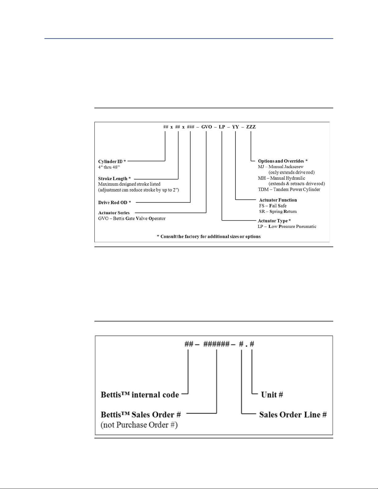
The catalog lists standard models intended to cover a wide range of sizes and applications.
Customers can use Figure 2.
(Linear Valve Operator Model Designation)
operator characteristics. If not included in the catalog lists, custom designed models are
also available for specialized thrust or stroke requirements or those beyond the scope of
this listing (including linear hydraulic operated operators).
Figure 2 Linear Valve Operator Model Designation
Section 2: Introduction
May 2014
to identify the key
To illustrate, a model number of 16x10x2.50-GVO-LP-SR-MH is an operator with a 16 [inch]
inside diameter cylinder, a 10 [inch] maximum stroke (adjustable down to 8 [inch] stroke),
a 2.50 [inch] outside diameter drive rod, and is low-pressure pneumatic spring return with
a manual hydraulic override.
Operators will also be identied with an individual serial number.
Figure 3.
(Linear Valve Operator Serial Number)
shows the form of the BettisTM serial number.
Figure 3 Linear Valve Operator Serial Number
Introduction
For example, a serial number of 00-123456-2.1 represents the rst unit on the second line
of sales order 123456.
4

Sections 3: Storage Instructions
May 2014
Installation, Operation and Maintenance Manual
Section 3: Storage Instructions
Proper storage is required when the operator will not be used immediately.
1. Remove all dirt, dust, grease, and contaminants from the exposed drive rod (1)
surface by using a soft cloth dampened with an appropriate oil-based solvent.
Avoid using abrasive material when cleaning rod surfaces.
2. Exposed drive rod (1) must be protected to avoid damage to the surface.
a. FS style operator: Drive rod is retracted into the cylinder (only a portion
of the rod is exposed). Lightly grease the exposed surface and wrap with
protective material if necessary.
b. SR style operator: Drive rod is fully extended from the cylinder. User must
protect the rod surface to avoid damage (which in turn will compromise
and/or damage the sealing capability during operation). Lightly grease
and wrap the rod surface with protective material.
3. Remove the plastic plugs (used to plug the pressure ports during assembly) and
replaced with steel plugs. Any controls present should also be plugged with steel
plugs.
E-90090003 Rev. A
NOTE:
Sealants such as pipe dope or Teon tape should be applied to steel plug threads.
4. Lightly lubricate all exposed threads and unpainted surfaces
(for example, bottom of pedestal plate).
5. Cover the operator to prevent accumulation of dirt and debris.
6. Repeat the storage steps listed above to ensure the proper storage condition (in
case the operator will be moved and stored again).
Indoor environment is the ideal storage condition for the operator.
For additional information on storage, please contact the manufacturer.
5
Storage Instructions

Installation, Operation and Maintenance Manual
E-90090003 Rev. A
Section 4: Operation
4�1 SR Operator
SR type operator contains spring which is located above the piston. Therefore, under spring
stroke, spring force will act on the piston to push the drive rod (1) into fully extended position.
To retract the drive rod (1), supply compressed air/Nitrogen to the piston (11) through the port
in the cylinder plate (4). Upon loss of supply pressure, the operator will fully extend the drive
rod (in other words, valve stem in retraction).
4�2 FS Operator
FS type operator contains spring which is located below the piston. Therefore, under spring
stroke, spring force will act on the piston to pull the drive rod (1) to fully retracted position.
To extend the drive rod (1), supply compressed air/Nitrogen to the piston (11) through the
port in the end cap (8). Upon loss of supply pressure, the operator will fully retract the drive rod
(in other words, valve stem in extension).
Sections 4: Operation
May 2014
Operation
6

Section 5: Preparation
May 2014
Section 5: Preparation
Before working (installation, operation, or maintenance) on the operator, be sure to read
through all the applicable sections of the manual to ensure that you are familiar with the
expected sequence of events.
5�1 Tools
Listed are the recommended tools and materials that may be required when working on
the operator. Additional tools and materials may be required depending upon specic
operator and/or task.
• Vernier/measurement ruler
• A set of SAE combination wrenches and sockets
• A set of SAE hex keys
• Strap or pipe wrench (small to medium sizes)
• Large size ring wrench/hammer wrench
• Torque wrench with suitable rating
• Lifting device or a crane (complete with slings, a pair of shackles or clevises)
• Air supply or nitrogen not exceeding the MAWP of the operator
• Block and bleed test valve assembly for air supply/Nitrogen
• Anti-seize (lubricant) compound
• Pipe thread sealant (for example, Teon tape, pipe dope)
• Commercial solvent (for example, Varsol)
Installation, Operation and Maintenance Manual
E-90090003 Rev. A
5�2 Pre-Installation Verification
NOTE:
GVO linear operators shipped mounted to valves have their travel adjusted properly by the
manufacturer and do not require further adjustment. Install valve with GVO linear operator
directly in line. GVO linear operators shipped without a valve have their travel adjusted based
on the valve topworks (if available). Verify and ne-tune (if needed) the travel adjustment
when installing operator on the valve.
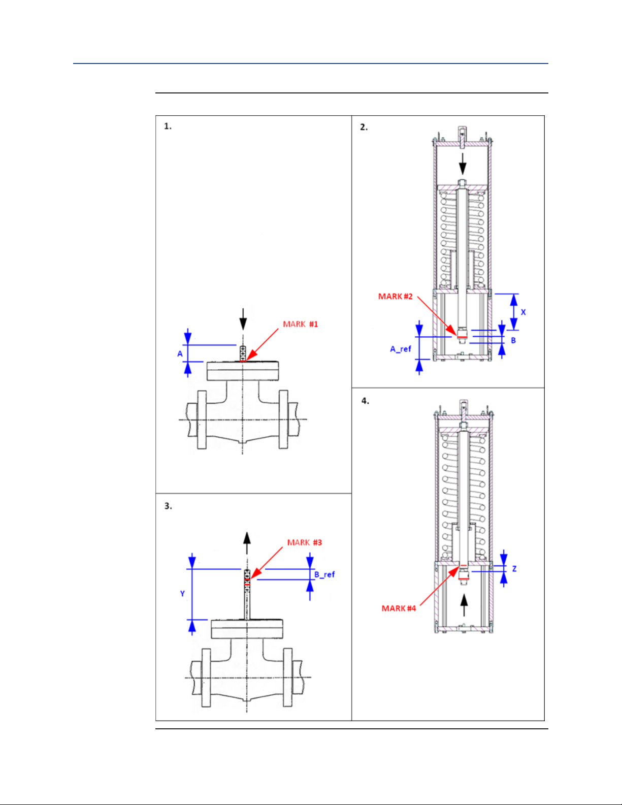
There are several critical measurements and markings to make before initial installation
of the operator on the valve. These measurements and markings are helpful for checking
or adjusting travel, however, it cannot be made after the operator is installed. Please refer
to Figure 4.
measurements.
NOTE:
Marks should be made with a marker, wax pen, or other tool that will not damage the sealing surfaces of the operator. Type FS style operator is used for illustration.
Follow the same instruction for SR style operator (with the exception of spring function).
7
(Measurement of Travel Adjustment for Valve and Operator)
when making
Preparation
Installation, Operation and Maintenance Manual
E-90090003 Rev. A
Figure 4 Measurement of Travel Adjustment for Valve and Operator
Section 5: Preparation
May 2014
Preparation
8

Section 5: Preparation
May 2014
1. Drive the valve stem fully into the valve body, ensuring that it is fully retracted
2. Actuate the operator (apply air to end cap side) to fully extend the drive
NOTE:
This will be spring stroke to fully extend the drive rod (if the operator is “SR” type).
Installation, Operation and Maintenance Manual
E-90090003 Rev. A
(consult valve manufacturer for procedure if required). If so equipped, remove valve
lever, handwheel, gear and/or jam nut/stop nut per valve-manufacturer instructions.
Strike the valve stem's threaded end using a soft mallet to retract valve stem fully.
Mark on the valve stem where it and the top of the valve ange align.
This is "MARK #1".
Measure from the top of the valve ange to the end of the valve stem using the
Vernier/measurement ruler. Record this value as "A".
A = ___________
rod (1). Mark on the swivel connector (80) the distance "A" up from the bottom of
the adapter plate. This is "MARK #2".
Measure from the mark to the bottom of the stem nut using the Vernier/measurement
ruler. Record this value as "B".
B = ___________
Also measure from the top of the body of the swivel connector (80) to the bottom of the
cylinder plate (4). Record this value as "X".
X = ___________
3. Pull the valve stem fully out of the valve body, ensuring that it is fully extended.
Mark on the valve stem a distance "B" down from the top of the valve stem.
This is "MARK #3".
Measure from the top of the valve ange to the top of the valve stem using the
Vernier/measurement ruler. Record this value as "Y".
Y = ___________
4. Actuate the operator (spring stroke) to fully retract the drive rod (1). Mark on the
drive rod (1) where it and the bottom of the cylinder plate (4) align (do not damage the drive rod's outside diameter sealing surface). This is "MARK #4".
NOTE:
This will be power stroke by applying air through cylinder plate port (if the operator is “SR” type).
9
Preparation

Installation, Operation and Maintenance Manual
E-90090003 Rev. A
Measure from the top of the body of the swivel connector (80) to the bottom of the
cylinder plate (4) using the Vernier/measurement ruler. Record this value as "Z".
Z = ___________
To check: Perform the calculations below:
Y - A = Maximum Valve Stem Travel (MVT) = ___________
X - Z = Maximum Operator Travel (MOT) = ___________
If maximum operator travel (MOT) is less than or equal to maximum valve stem travel
(MVT), that means end stop (32) is factory set properly. Further verication is required
during the valve installation. If MOT is larger than MVT, refer to Section 8.
End Stop Adjustment)
for details on how to adjust the operator travel stop during valve
installation.
Section 5: Preparation
May 2014
(Operator
Preparation
10
 Loading...