

Manual: Bettis RPE-Series Installation, Operation and Maintenance Manual
Table of contents
 Loading...
Bettis Manual: Bettis RPE-Series Installation, Operation and Maintenance Manual Manuals & Guides
Installation, Operation and Maintenance Manual
Bettis RPE-Series
Rack and Pinion Pneumatic Actuators
DOC.IOM.BE.EN Rev. 9
March 2019


Installation, Operation and Maintenance Manual
DOC.IOM.BE.EN Rev. 9
Table of Contents
Section 1: Before You Start
1.1 Installation, Operation and Maintenance Reference Documents ................... 1
1.2 Warehouse Storage ...................................................................................... 1
1.3 On-Site Storage ............................................................................................ 2
Section 2: Introduction
2.1 Identification ................................................................................................ 3
2.2 Intended Use ................................................................................................. 5
2.3 Specifications ................................................................................................ 5
Section 3: Configuration Code
Table of Contents
March 2019
Section 4: Installation
4.1 Before You Start ............................................................................................9
4.2 Actuator Rotation Direction .......................................................................... 9
4.2.1 Valve Rotation .................................................................................... 9
4.2.2 Position After Failure ........................................................................ 10
4.3 Principles of Operation ................................................................................ 10
4.3.1 Solenoid Valve .................................................................................. 10
4.3.2 Ingress Protection (IP) rating ............................................................ 11
4.3.3 Double-Acting Actuators .................................................................. 12
4.3.4 Spring-Return Actuators ................................................................... 13
4.4 Actuator Assembly Codes ........................................................................... 14
4.5 Actuator to Valve Installation ...................................................................... 15
4.6 Mounting of control and feedback accessories ............................................ 18
4.7 Recommended Tubing Sizes ....................................................................... 18
Section 5: Mechanical Stroke Adjustment
5.1 Travel Stop Adjustment ............................................................................... 20
5.1.1 Double-Acting Actuators .................................................................. 20
5.1.2 Spring-Return Actuators ................................................................... 20
5.1.3 Angular Displacement ......................................................................21
Section 6: Maintenance
6.1 Normal Maintenance .................................................................................. 22
6.2 Inspection and Repair .................................................................................. 23
6.2.1 Service Kits .......................................................................................23
6.2.2 Spring-Return Actuator ....................................................................23
Table of Contents
Section 7: Decommission (Out of Service)
7.1 Before You Start ..........................................................................................24
7.2 Removing the actuator from the valve ........................................................ 25
I

Table of Contents
March 2019
Section 8: Disassembly
Section 9: Reassembly
Installation, Operation and Maintenance Manual
DOC.IOM.BE.EN Rev. 9
8.1 Removing End Caps (Sizes 25 to 600) .......................................................... 27
8.2 Removing End Caps (Sizes 950 to 4000) ...................................................... 29
8.3 Removing Spring Cartridges or Springs ....................................................... 30
8.4 Removing of Limit Stop ...............................................................................31
8.5 Removing Pistons ....................................................................................... 31
8.6 Removing Pinion .........................................................................................32
8.7 Cleaning the Components .......................................................................... 33
9.1 Grease Instructions .....................................................................................35
9.2 Reassembly of the pinion ............................................................................ 36
9.3 Reassembly of the pistons ........................................................................... 37
9.4 Reassembly and settings of the limit stops .................................................. 39
9.5 Reassembly of the end caps ........................................................................ 40
9.5.1 Double-Acting actuators .................................................................. 40
9.5.2 Spring-Return actuators ................................................................... 41
9.5.3 Spring-Return actuators - Size 950 to 4000 ...................................... 42
9.6 Basic function and Air Leak Test .................................................................. 45
Section 10: Troubleshooting
10.1 Mechanical Problems ..................................................................................46
10.2 Pneumatic Problems ...................................................................................47
10.3 Electrical Problems ...................................................................................... 48
Section 11: Parts List and Spare Parts Recommendations
11.1 Actuator sizes RPE25 to RPE600 ..................................................................49
11.2 Actuator sizes RPE950 to RPE2500 .............................................................. 50
11.3 Actuator size RPE4000 ................................................................................ 51
Appendix A: Spring Load Removal
A.1 Spring load relief ......................................................................................... 52
Appendix B: Tool & Torque Table
Appendix C: Full Stroke Adjustment Option
C.1 Full Stroke Adjustment Option .................................................................... 56
C.2 Convert a Standard Actuator into a Full Stroke Adjustment Version ............ 57
11.3.1 Procedure ........................................................................................ 58
C.3 Full Stroke Adjustment Setting .................................................................... 59
11.3.2 Factory Setting Procedure ................................................................ 59
11.3.3 Setting the Full Stroke Adjustment Screw to the Required Angle ...... 60
II
Table of Contents

Installation, Operation and Maintenance Manual
DOC.IOM.BE.EN Rev. 9
Section 1: Before You Start
This section explains:
• Base safety procedures.
• Where to find detailed information relating safety.
• Storage guidelines.
Installation, adjustment, putting into service, use, assembly, disassembly and maintenance
of the pneumatic actuator must be performed by qualified personnel.
NOTICE
Failure to follow the above guidelines will void warranty.
WARNING
Section 1: Before You Start
March 2019
Actuator must be isolated both pneumatically and electrically before any (dis)assembly
starts. Before mounting or (dis)assembly, the actuator consult the relevant sections of this
manual.
1.1 Installation, Operation and Maintenance Reference Documents
Before you start, read the following documents:
• All chapters in this manual.
• Safety Guide (Document No. DOC.SG.BE.1).
For Safety Instrumented Systems application, read the following document:
• SIL Safety Manual Bettis RPE-Series (Document No. DOC.SILM.BE.EN).
NOTICE
Failure to read the Safety Guide will void the warranty.
Not following the instructions of the Safety Guide can lead to failure of the product and
harm to personnel or equipment.
1.2 Warehouse Storage
• All actuators should be stored in a clean, dry warehouse, free from excessive
vibration and rapid temperature changes.
• All actuators should not be stored directly to the floor surface - it must be placed
in racks/shelves or use a pallet.
Before You Start
1

Section 1: Before You Start
March 2019
1.3 On-Site Storage
• All actuators should be stored in a clean, dry warehouse, free from excessive vibra-
tion and rapid temperature changes.
• Prevent moisture or dirt from entering the actuator. Plug or seal both air connec-
tion ports.
NOTICE
Failure to follow the above guidelines (Warehouse and On Site Storages) will void warranty.
Installation, Operation and Maintenance Manual
DOC.IOM.BE.EN Rev. 9
2
Before You Start

Installation, Operation and Maintenance Manual
DOC.IOM.BE.EN Rev. 9
Section 2: Introduction
This section explains:
• How to identify the received product.
• The intended use of the product.
• Construction details.
• Actuator specifications.
2.1 Identification
The Bettis™ RPE-Series Rack and Pinion actuators are available as double-acting or
spring-return versions. 12 models are available, ranging from 23 Nm to 4041 Nm
(206 to 35765 lbf.in)nominal torque output.
The Bettis RPE-Series uses standardized interfaces for solenoid, switchbox or positioner
mounting (VDI/VDE3845; NAMUR). The valve interface is equipped with an insert in the
pinion bottom that allows both ISO5211 or DIN3337 mounting.
Section 2: Introduction
March 2019
The springs in the spring-return version allow a fail action in case of loss of air supply
pressure (Fail-to-Close or Fail-to-Open).
As from size RPED150 double-acting versions have flat end caps to reduce actuator length
and internal air volume.
Introduction
3
25 100
150 -
600
4000
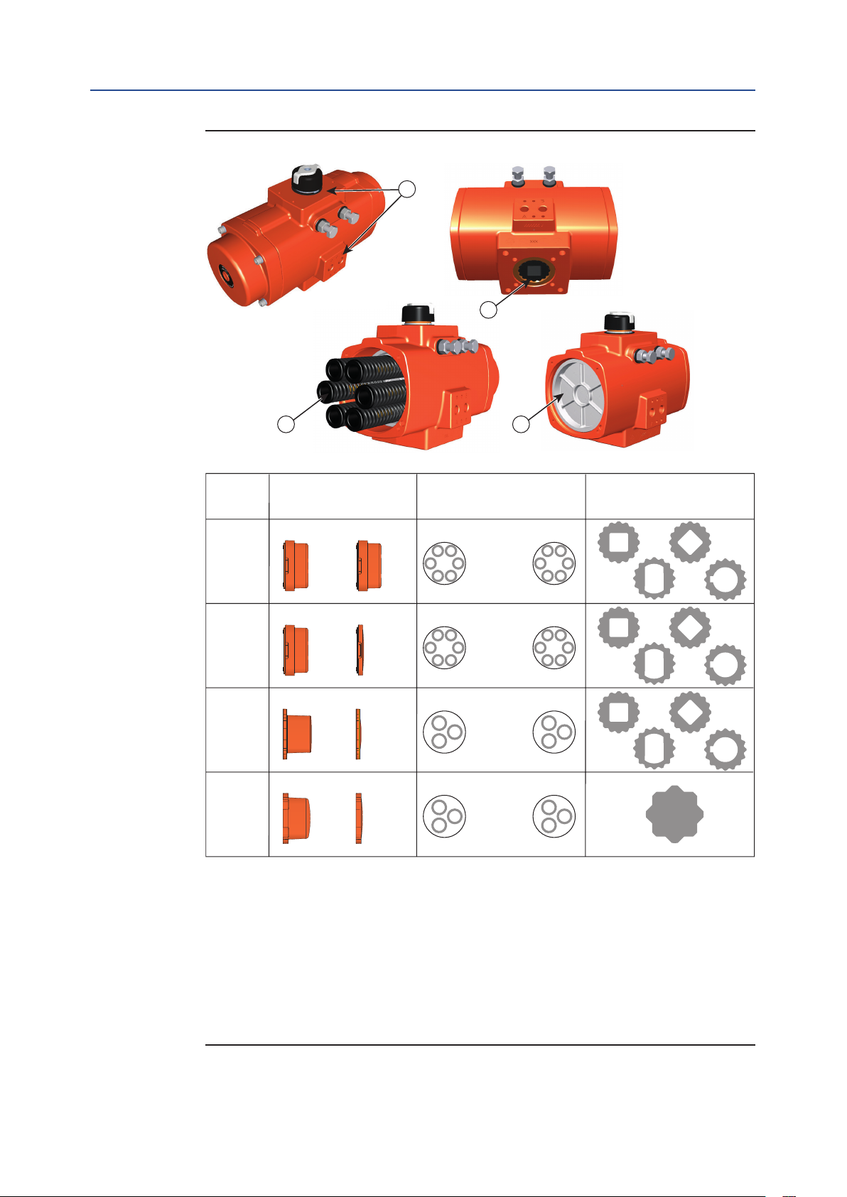
Size End cap design
5
Spring design
6
Pinion bottom /
Insert design
2
950 -
2500
SR
Maximum 12
spring cartridges
Maximum 6
loose springs
Left
Right
Left Right
Left Right
DA
SR DA
SR DA
SR DA
Maximum 12
spring cartridges
Maximum 6
loose springs
Left Right
Notes
1. Top auxilliaries and Solenoid interface (VDI/VDE 3845; NAMUR) for size 25 to 4000.
2. Valve interface availalable according ISO5211 or DIN 3337.
Actuator sizes 25 to 2500 can be fitted with drive inserts with various inner shapes.
Actuator size 4000 is fitted with a double square; parallel and diagonal.
3. Spring-Return actuators: - with springs
4. Double-Acting actuators: - no springs
5. Actuator sizes 25 to 100 have high end caps for double-acting and spring-return models.
Actuator sizes 150 to 4000 have low end caps for double-acting models and high end caps
for spring return models.
6. Actuator sizes 25 to 600 are fitted with a maximum of 12 spring cartridges.
Actuator sizes 950 to 4000 are fitted with a maximum of of 6 loose springs.
1
2
3 4
Section 2: Introduction
March 2019
Figure 1 Identification
Installation, Operation and Maintenance Manual
DOC.IOM.BE.EN Rev. 9
4
Introduction

Installation, Operation and Maintenance Manual
DOC.IOM.BE.EN Rev. 9
2.2 Intended Use
The Bettis RPE Rack and Pinion actuators are intended for the automation and operation of
quarter-turn valves like Butterfly, Ball and Plug valves.
Rack and Pinion actuators can also be used to operate dampers or any other quarter-turn
applications.
2.3 Specifications
Table 1. Pressure Range
Actuator Type Pressure
Double-Acting 0.2 to 8 bar (2.9 to 116 psi)
Spring-Return
Table 2. Operating Media
6 to 8 bar (87 to 116 psig), with maximum spring set
3 to 8 bar (43.5 to 116 psig), reduced spring quantity
Section 2: Introduction
March 2019
Actuator Type Operating Media
Air, dry or lubricated and inert gases
Dew point at least 10K below ambient temperature
Double-Acting and Single Acting
1. Recommended air quality according ISO 8573-1 for normal operation: 7-5-4.
For sub-zero applications, take appropriate measures
Mentioned pressure levels are "gauge pressures".
Gauge pressure is equal to absolute pressure minus
atmospheric pressure.
NOTE:
Use of filters, pressure regulators, lubricator and an oil/water separator mounted in the air
supply line, will allow a smooth and durable operation of the actuator.
For lubricated supply air, it is recommended to use a non-detergent oil without aggressive
additives, VG32, group 2 (ISO 3448).
Table 3. Temperature Range
Actuator Type Temperature
Standard -20°C to 80°C (-4°F to +176°F)
Option: Low Temperature -40°C to +80°C (-40°F to +176°F)
Option: High Temperature -10°C to +120°C (+14°F to +250°F)
Introduction
5
A
B
Section 2: Introduction
March 2019
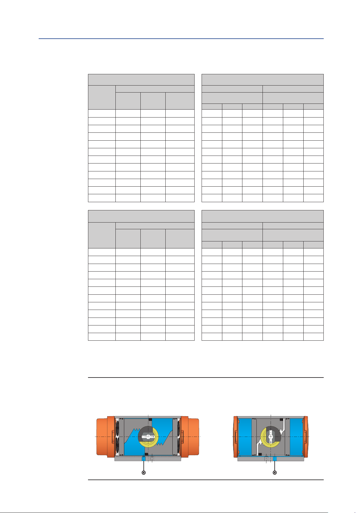
Table 4. Air Volumes and Consumption
Actuator
model
RPE 0025 0.14 0.20 0.08 0.36 0.64 1.2 0.48 0.88 1.7
RPE 0040
RPE 0065 0.40 0.56 0.22 1.02 1.8 3.4 1.3 2.4 4.7
RPE 0100 0.6 0.9 0.3 1.5 2.7 5.0 2.0 3.8 7.2
RPE 0150 1.0 0.8 0.5 2.4 4.3 8.1 2.1 3.6 6.7
RPE 0200
RPE 0350
RPE 0600 3.6 3.3 2.1 9.4 17 31 8.7 15 28
RPE 0950
RPE 1600 7.9 7.3 5.4 21 37 69 20 35 64
RPE 2500 12.6 11.9 8.3 34 59 109 32 56 104
RPE 4000 21.7 19.0 13.5 57 100 187 52 89 165
Installation, Operation and Maintenance Manual
DOC.IOM.BE.EN Rev. 9
Actuator volumes:
Maximum volume (in liters) Outward Stroke Inward Stroke
Central
chamber
1
End cap
chamber
2
Displaced
3
volume
Double-Acting
and Spring-Return
2 4 8 2 4 8
0.26 0.37 0.15 0.67 1.2 2.2 0.89 1.6 3.1
1.3 1.0 0.7 3.2 5.7 11 2.8 4.9 9.1
2.1 1.9 1.2 5.5 9.8 18 5.0 8.8 16
4.9 4.6 3.2 13 23 43 12 22 40
Consumption per stoke
(in liters, pressure in barg)
Double-Acting only
Consumption per stoke
(in Cu.in., pressure in psig)
Double-Acting only
Actuator
model
Actuator volumes:
Maximum volume (Cu.in.) Outward Stroke Inward Stroke
Central
chamber
1
End cap
chamber
2
Displaced
3
volume
Double-Acting
and Spring-Return
40 80 120 40 80 120
RPE 0025 8.5 12.2 4.7 28 52 75 38 72 106
RPE 0040
RPE 0065
15.9 23 8.9 53 96 140 71 133 196
24 34 13.5 81 148 215 107 200 294
RPE 0100 36 53 19.9 118 216 314 165 310 455
RPE 0150 58 47 32 192 352 512 163 293 424
RPE 0200 76 64 44 255 466 676 220 397 573
RPE 0350 131 115 76 436 796 1157 392 709 1025
RPE 0600 222 201 129 742 1354 1967 683 1237 1790
RPE 0950 301 279 196 1025 1854 2682 966 1735 2505
RPE 1600 484 447 328 1662 2997 4331 1560 2792 4024
RPE 2500 769 728 508 2630 4751 6873 2515 4523 6530
RPE 4000 1324 1159 825 4477 8130 11782 4022 7219 10416
Notes:
1. Pistons at 90° outward position.
2. Pistons at 0° inward position.
3. Stroke is 90°.
Figure 2 Actuator air volumes
Central air chamber volume
Double-Acting and Spring-Return
6
End cap air chamber volume
Double-Acting only
Introduction
Installation, Operation and Maintenance Manual
DOC.IOM.BE.EN Rev. 9
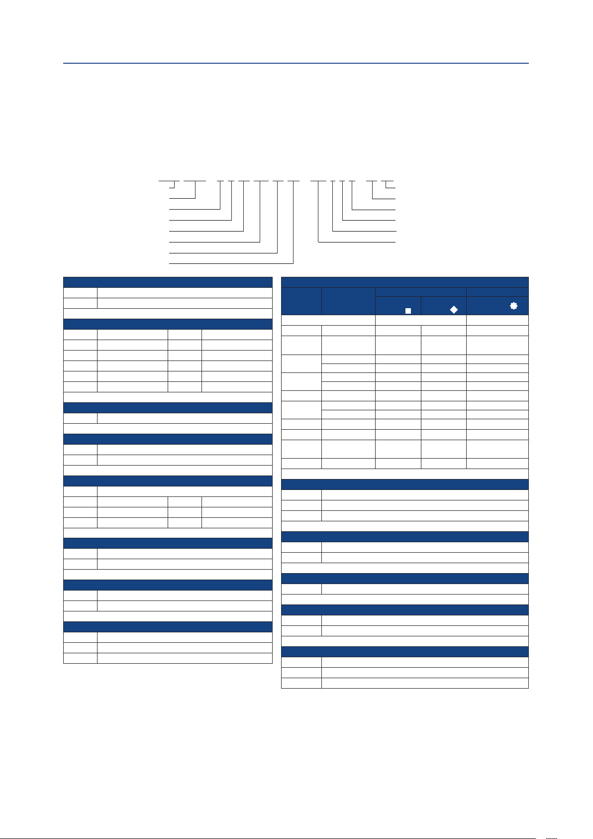
Section 3: Configuration Code
This section explains:
• How to create the configuration code for a actuator.
RPES 0150 - N U 40 CW AL TN - L19 S K A - 00 XX
Type
Size
Rotation angle
Threads
Spring set
Rotation
Pinion material
Valve interface
Section 3: Configuration Code
March 2019
Miscellaneous options
Internal code 1
Color / finish
Visual indicator
Temperature
Valve stem connection
Type
RPED Double Acting
RPES Spring Return
Size
0025 Size 0025 0350 Size 0350
0040 Size 0040 0600 Size 0600
0065 Size 0065 0950 Size 0950
0100 Size 0100 1600 Size 1600
0150 Size 0150 2500 Size 2500
0200 Size 0200 4000 Size 4000
Rotation angle
N 90° rotation angle
Threads
M Metric ISO 5211
U UNC/NPT/Imperial
Spring Set
00 Double Acting (no springs)
10 Spring Set 10 40 Spring Set 40
20 Spring Set 20 50 Spring Set 50
30 Spring Set 30 60 Spring Set 60
Rotation direction
CW Spring to Close/Clock Wise
CC Spring to Open/Counter Clock Wise
Pinion Material
AL High Grade Aluminium, Hard anodized
SS Stainless steel ASI 316 (+ A4-70 SS fasteners)
Valve Interface
TN Standard ISO 5211 interface
SY Small interface with center plate (DIN3337)
LY Large interface with center plate (DIN3337)
(2
Notes:
See next page.
Valve Stem Connection
Actuator
size
0025 11mm / 0.433" L11 D11 Q11
0040 &
0065
0100
0150
0200 22mm / 0.866" L22 D22 Q22
0350
0600 27mm / 1.063" L27 D27 Q27
0950 36mm / 1.417" L36 D36 Q36
1600 &
2500
4000 (355mm / 2.165" Q55 Q55 Q55
Temperature Range
S Standard: -20°C to +80°C (-4°F to +176°F)
H High: -10°C to +120°C (+14°F to +250°F)
L Low: -40°C to +80°C (-40°F to +176°F)
Visual Indication Code
K Standard (Knob)
N No Visual Indication
Finish
(7
B Standard coating (Bettis Orange)
Internal code 1
00 Standard
10 Stainless steel AISI316 (A4-70) end cap screws
Miceleanuous options
XX Standard
H1 1/2" High Flow plate
P1 1/2" Porting according EN 15714-3 (only sizes 950-4000)
Square
No insert 000 Not applicable
14mm / 0.551" L14 D14 Q14
17mm / 0.669" D17 Q19
19mm / 0.748" L19
17mm / 0.669" D17 Q22
19mm / 0.748" L19
22mm / 0.866" D22 Q27
27mm / 1.063" L27
46mm / 1.811" L46 D46 Q46
Aluminum Stainless Steel
Parallel
drive
Diagonal
drive
Star drive
(7
(4
Configuration Code
7

Section 3: Configuration Code
March 2019
Notes:
1. The options, listed here, are all options available. Not all options apply to all configurations.
2. Valve Interface: Option "S"; Small Interface with Center Plate (DIN3337) is not
available for size 0025, 0950 and 4000. Option "L"; Large Interface with Center
Plate (DIN3337) is not available for size 1600 and 2500.
3. Size 4000 does not have inserts but has two inner squares (diagonally and parallel
oriented) directly in the bottom of the pinion.
4. Actuators with stainless steel pinions do not have inserts but have two inner
squares (diagonally and parallel oriented aka "Star Drive") directly in the bottom of
the pinion.
5. Contact you local Bettis representative for additional insert options.
6. PED Group 1 Label only available up to size 950.
7. Actuators with the default hard anodized pinions, come with stainless steel grade
A2 (AISI304) end cap screws.
Optional, the actuator is available with stainless steel grade A4-70 (AISI316) end
cap screws.
Select option 10 in the "Internal code 1" segment in case stainless steel grade A4
(AISI316) end cap screws are required.
Installation, Operation and Maintenance Manual
DOC.IOM.BE.EN Rev. 9
8
Configuration Code
Installation, Operation and Maintenance Manual
DOC.IOM.BE.EN Rev. 9
Section 4: Installation
This section explains:
• The actuator rotation direction.
• In which position the actuator will end after a failure.
• Principles of operation:
— Solenoid operation.
— Double acting and Spring return operation.
• Assembly codes.
• Actuator to valve assembly.
4.1 Before You Start
Section 4: Installation
March 2019
SAFETY
In case of an air or electrical failure, it is important to know the behavior of the actuator.
Before mounting the actuator on a valve, consult the following sections below.
4.2 Actuator Rotation Direction
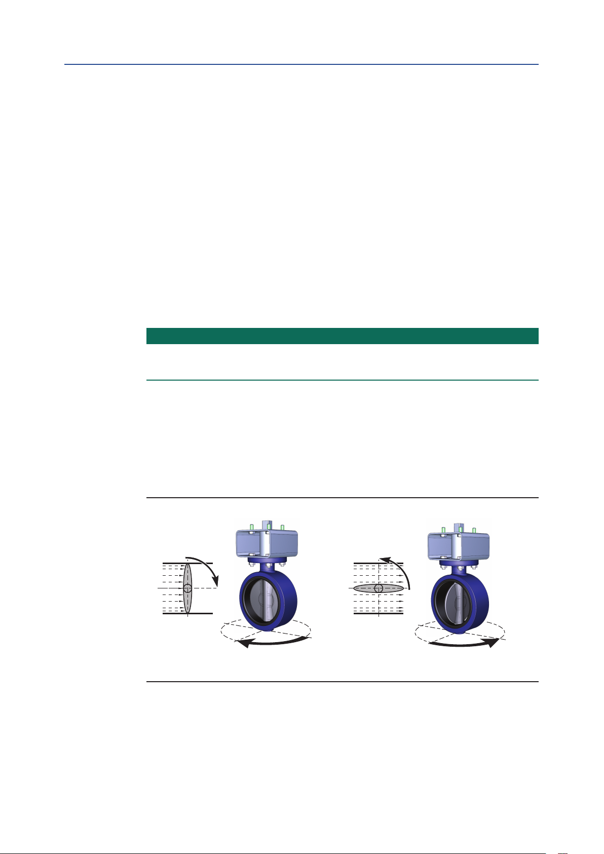
4.2.1 Valve Rotation
For the following paragraphs we assume that valves rotate as indicated in figure 3.
Figure 3 Normal valve rotation
Installation
The valve is closed after
a clockwise rotation.
The valve is open after
a counterclockwise rotation.
9

A
BA
Section 4: Installation
March 2019
4.2.2 Position After Failure
The position of the actuator after a failure depends on the:
1. Principle of operation (see paragraph 4.3)
2. Assembly codes (see paragraph 4.4)
3. Kind of failure. Refer to the table below.
Table 5. Position After Failure
Installation, Operation and Maintenance Manual
DOC.IOM.BE.EN Rev. 9
Principle of
Operation
Assembly Code Kind of Failure Position
CW
Double-Acting
Actuator
Single-Acting
CW
(Spring-Return)
Actuator
4.3 Principles of Operation
4.3.1 Solenoid Valve
All actuators can be either piped with solid or flexible tubing with the solenoid valve
mounted remotely from the actuator or by mounting a VDI/VDE 3845 (NAMUR) designed
solenoid valve DIRECTLY onto the NAMUR mounting pad on the side of the actuator.
Pressure Not defined
Signal Closed
Supply Voltage Closed
Pressure Not defined
Signal Open
Supply Voltage Open
Pressure Closed
Signal Closed
Supply Voltage Closed
Pressure Open
Signal Open
Supply Voltage Open
10
Figure 4 Typical solenoid operation
Spring-Return Operation Double-Acting Operation
Installation

Installation, Operation and Maintenance Manual
DOC.IOM.BE.EN Rev. 9
The table below represents the cycle time (operating time) per different Actuator sizes:
Table 6. Operating Speed
Cycle time in seconds
Actuator
size
25 0.5 0.4 0.5 0.4
40 0.6 0.5 0.6 0.5
65 0.7 0.5 0.6 0.6
100 0.8 0.6 0.8 0.7
150 1.0 0.8 0.9 0.8
200 1.3 0.9 1.0 1.0
350
600 3.2 1.9 2.2 2.2
950 6.6 2.2 2.4 2.0
1600 10.6 3.5 3.6 3.3
2500 16.9 5.7 5.8 5.2
4000 29.1 9.2 9.2 9.0
Operating time is average with actuator under load and solenoid valve fitted.
pressurized
Spring-Return Double-Acting
A-port
1.9 1.3 1.4 1.5
Spring
stroke
Section 4: Installation
A-port
pressurized
March 2019
B-port
pressurized
Test conditions:
1. Solenoid with flow capacity: 0.6 m3/hr
2. Pipe diameter: 6mm
3. Medium: clean air
4. Supply pressure: 5.5 bar (80psi)
5. Load: with average load
6. Stroke: 90°
7. Temperature: Room temperature
4.3.2 Ingress Protection (IP) rating
Bettis RPE actuators are IP66/IP67 rated. In case of IP66 or IP67 requirements, take
precautions that comply with the IP66/IP67 requirements to prevent moisture or dust
from entering the actuator through the open air exhaust port(s), either directly on the
actuator or at the exhaust ports of the connected solenoid valve.
We recommend to connect tubing to the exhaust(s) and lead this into a dry and dust free
area, or to use check valves in the exhaust.
Installation
11
A
BA
A
B
B
Section 4: Installation
March 2019
Installation, Operation and Maintenance Manual
4.3.3 Double-Acting Actuators
The operating principle, as explained here, is applicable for actuators with assembly code
CW (direct acting).
• Applying supply pressure to port A will move the pistons outward to the "Open"
position of the valve.
• Applying supply pressure to port B will move the pistons inward to the "Close"
position of the valve.
• For assembly codes CC, the operating principle is reversed (reverse acting).
Figure 5 Double-Acting Operation
Outward Stroke
DOC.IOM.BE.EN Rev. 9
12
Inward Stroke
Installation

Installation, Operation and Maintenance Manual
A
A
B
A
DOC.IOM.BE.EN Rev. 9
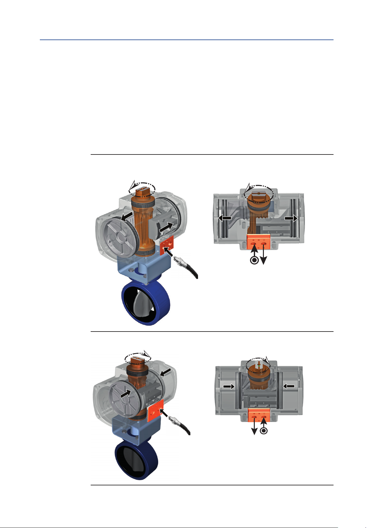
4.3.4 Spring-Return Actuators
The operating principle, as explained here, is applicable for actuators with assembly code
CW (direct acting).
• Applying supply pressure to port A will move the pistons outwards to the "Open"
position of the valve.
• Venting the supply pressure from port A will cause the springs to move the pistons
inwards to the "Close" position of the valve.
• For assembly codes CC, the operating principle is reversed (reverse acting).
Figure 6 Stroke Movements
Outward Stoke
Section 4: Installation
March 2019
Installation
Inward Stroke
13

AB
A
B
A
B
A
B
Pinion and
cam position
Dot in
pinion slot
Default
pistons position
Reversed
pistons position
Pinion 90°
rotated
AB
A
B
A
BA
B
Pinion and
cam position
Dot in
pinion slot
Default
pistons position
Reversed
pistons position
Springs
Pinion 90°
rotated
Section 4: Installation
Installation, Operation and Maintenance Manual
March 2019
4.4 Actuator Assembly Codes
Figure 7 Assembly Code - Double-Acting
Assembly code: CW Assembly code: CC
= Standard, Clockwise-to-Close rotation = Reverse, Counterclockwise-to-Open
= Fail-to-Close = Fail-to-Open
DOC.IOM.BE.EN Rev. 9
A = Rotation when central air chamber is pressurized.
B = Rotation when end cap air chambers are pressurized.
All views are from above. Pistons are shown in inward position.
Figure 8 Assembly Code - Spring-Return
Assembly code: CW Assembly code: CC
= Standard, Clockwise-to-Close rotation = Reverse, Counterclockwise-to-Open
= Fail-to-Close = Fail-to-Open
14
Installation
Installation, Operation and Maintenance Manual
DOC.IOM.BE.EN Rev. 9
4.5 Actuator to Valve Installation
WARNING: MOVING PARTS
Actuator must be isolated pneumatically and electrically before any (dis)assembly starts.
Stay away from moving parts to prevent serious injuries. When test cycling the actuator
and valve assembly by applying pressure to the A or B port, be aware that there are moving
parts like pinion top, actuator to valve coupling and the valve- blade, ball, plug, etc.
NOTICE
The actuator is designed to be installed, commissioned and maintained using generic tools
like wrenches, Allen keys and screwdrivers. For the removal of inserts, a special extractor
tool can be supplied on request.
During assembly to the valve, do not hit with hammer on pinion top. This can damage the
pinion top washer and cause premature failure.
Section 4: Installation
March 2019
Before mounting the actuator on the valve or valve bracket, be sure that both the
actuator and the valve are in the same closed or open position.
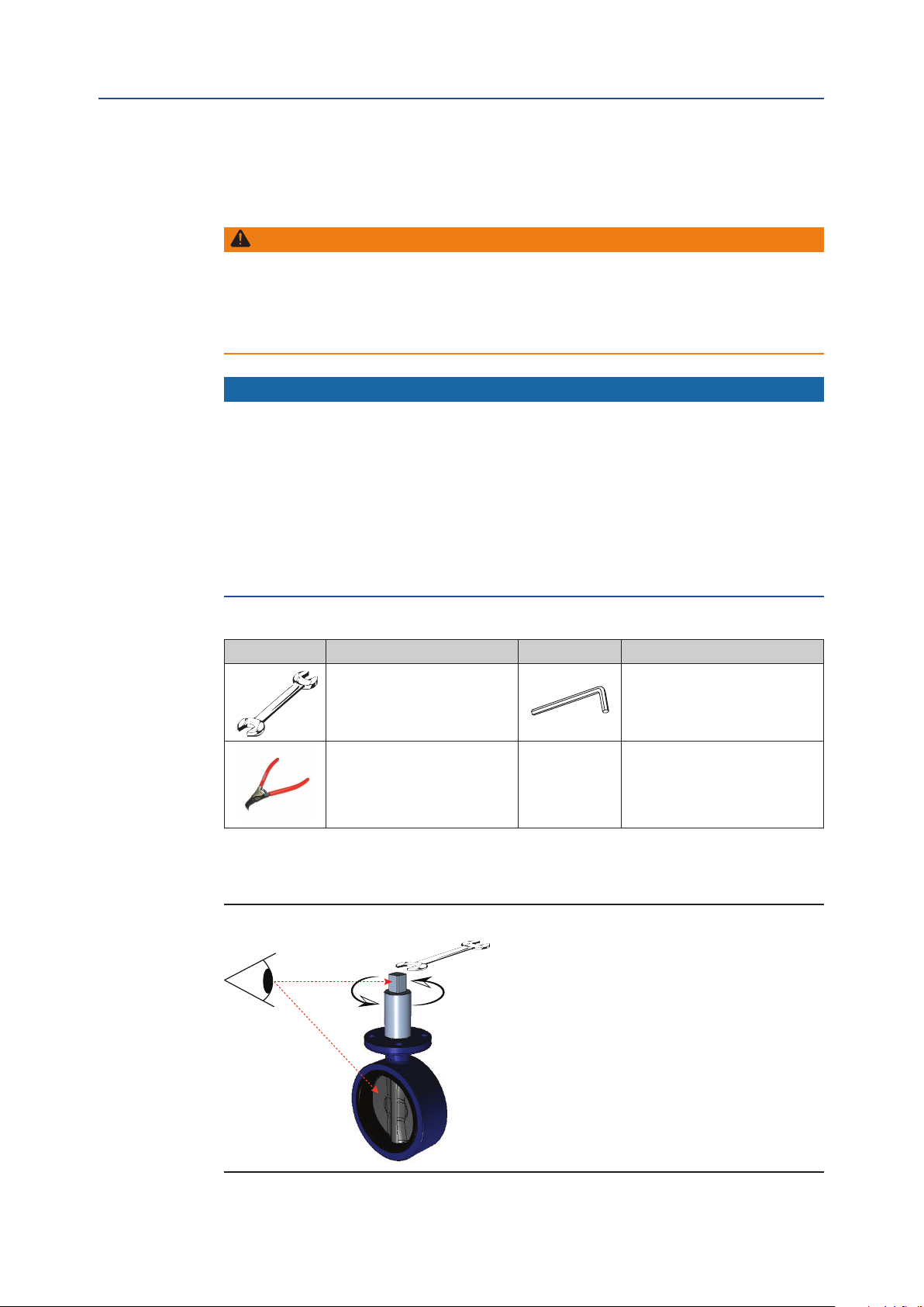
Refer to Appendix B, Tool and Torque tables, for using the right size tool.
Table 7. Tool Table
Symbol Tool Symbol Tool
Wrench – All types and sizes.
Metric and Imperial
Circlip Pliers
1. Remove handle nut, handle, lock washer, and etc. from the valve if required.
2. Visually check to make sure the valve is CLOSED.
Figure 9 Valve handle removal
Allen key
Installation
15
Section 4: Installation
March 2019
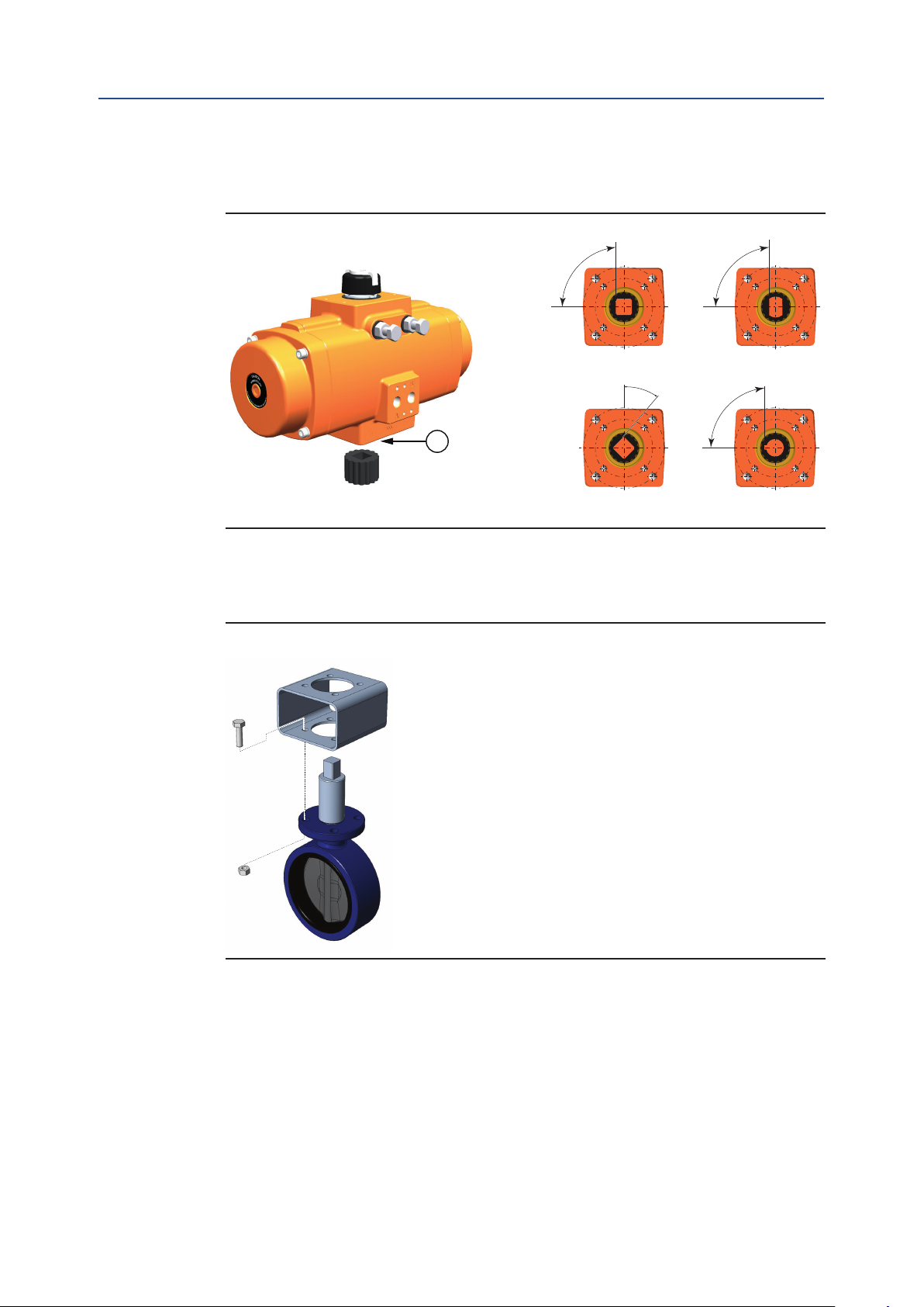
3. When required, check if the insert drive (23) is mounted. If not, use a plasticmallet
Figure 10 Insert drive Installation
Installation, Operation and Maintenance Manual
DOC.IOM.BE.EN Rev. 9
and tap slightly until the reducer square is in the required position.
90°
90°
Parallel
square
45°
Flat head
90°
23
Diagonal
square
Round with
key way
4. Install the bracket to the valve flange. Tighten all bolts and nuts and apply the correct torque.
Figure 11 Bracket Installation
16
Installation
Loading...