

Installation, Operation and Maintenance Manual
Bettis M Series
Stainless Steel Scotch Yoke Actuators
MAN-02-01-39-0704-EN Rev. 1
May 2020

Notes
May 2020
Installation, Operation and Maintenance Manual
MAN-02-01-39-0704-EN Rev. 1
This page intentionally left blank

Installation, Operation and Maintenance Manual
MAN-02-01-39-0704-EN Rev. 1
Table of Contents
Section 1: Introduction
1.1 General Application ....................................................................................... 1
1.2 Technical Data ...............................................................................................1
1.3 Installation .................................................................................................... 2
Section 2: Maintenance
Maintenance ........................................................................................................... 3
Section 3: Jackscrew Override
3.1 Jackscrew Operating Instructions .................................................................. 4
3.2 Actuator Stroke Adjustment .......................................................................... 4
3.3 Models 006 through 270 .............................................................................. 4
3.4 Models 370, 740 and 575 .............................................................................. 5
Table of Contents
May 2020
Section 4: Manual Handpump Hydraulic Override
4.1 Hydraulic Fluid Level .................................................................................... 10
4.2 Remote Mounting the Handpump ..............................................................10
Section 5: Integral Proximity Switch Mounting
Integral Proximity Switch Mounting ...................................................................... 11
Section 6: Spring Conversion to change Operating Pressure
Spring Conversion to change Operating Pressure .................................................. 12
Section 7: Failure Mode Change – Spring-Return
Failure Mode Change – Spring-Return ................................................................... 13
Section 8: Removal of Actuator from Valve
Removal of Actuator from Valve ............................................................................ 14
Section 9: Disassembly
9.1 Disassembly of Symmetric Yoke Actuators .................................................. 15
9.2 Disassembly of Canted Yoke Actuators ........................................................ 17
Table of Contents
i

Table of Contents
May 2020
Section 10: Assembly
Section 11: Operating Instructions
Section 12: Important Safeguards
Section 13: Additional Safety Instructions for Actuators
used in a Potentially Explosive Atmosphere
under ATEX 2014/34/EU
Installation, Operation and Maintenance Manual
MAN-02-01-39-0704-EN Rev. 1
10.1 Assembly of Symmetric Yoke Actuators ...................................................... 18
10.2 Spring-Return Only ..................................................................................... 21
10.3 Assembly of Canted Yoke Actuators ............................................................ 22
Operating Instructions .......................................................................................... 23
Important Safeguards ........................................................................................... 24
13.1 Marking ...................................................................................................... 25
13.2 Selection ..................................................................................................... 25
13.3 Installation .................................................................................................. 25
13.4 Maintenance ............................................................................................... 25
Section 14: Additional Safety Instructions for Actuators
used in Emergency Shut-down Service
or IEC 61508 safety integrity
level (SIL) Compliant Installations
Additional Safety Instructions for Actuators used in Emergency Shut-down
Service or IEC 61508 safety integrity level (SIL) Compliant Installations ................. 26
ii
Table of Contents

Installation, Operation and Maintenance Manual
MAN-02-01-39-0704-EN Rev. 1 May 2020
Section 1: Introduction
Section 1: Introduction
1.1 General Application
Actuators are designed for "ON-OFF" or modulating control of any quarter-turn ball,
buttery, rotary plug or damper style valve application.
1.2 Technical Data
Supply Pressure 40 - 160 psig, see product nameplate
Supply Medium Any pneumatic uid compatible with materials of construction
Temperature Rating
Angular Rotation 90 degrees ± 8 degrees
Standard Range: -20 °F to 210 °F
Optional Range: -65 °F to 300 °F
NOTE:
Language translations of the safety related portions of this document are available at
www.emerson.com
Introduction
1

Section 1: Introduction
May 2020
1.3 Installation
The actuator can be mounted parallel or perpendicular to pipeline. The actuator can be
installed in any convenient position including vertical, horizontal or upside down.
A. Begin by bolting the mounting bracket to actuator only hand tight.
B. Install coupling on valve. Remove or disable any stops on the valve.
Use only the actuator position stops!
C. Install the actuator and bracket to valve being sure to leave all fastener
connections hand tight. If possible, stroke valve and actuator to a half open
position and physically shift actuator back and forth until coupling and all
fasteners are centered then tighten all bolts and nuts. This procedure will
accurately align valve stem to actuator output shaft and prolong valve stem seal
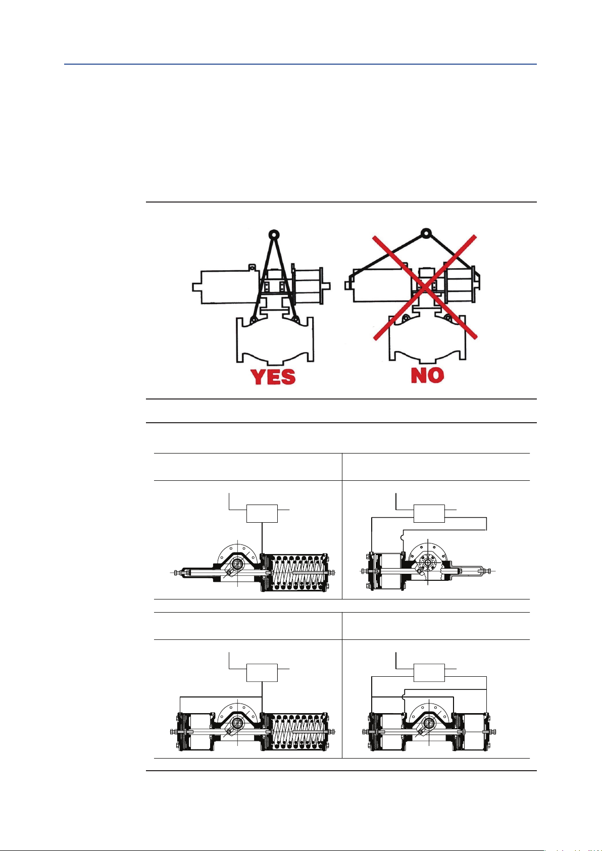
life. Lift the actuator at a balance point near the center housing. Do not lift the
weight of the valve, see Figure 1.
D. Cycle valve / actuator assembly and conrm smooth operation.
E. Adjust the actuator travel stops for perfect valve alignment in both open and
closed positions.
Installation, Operation and Maintenance Manual
MAN-02-01-39-0704-EN Rev. 1
NOTE:
If the valve disk is torque seated (E.G. Vanessa buttery), close the valve against the
actuator stop, then unscrew the stop until turns freely, then screw the stop back in until
it stops, then turn the stop with a wrench one additional turn and lock into place.
F. Tubing Connections – some models utilize two pistons for added power. Spring
return (single acting) dual cylinders designs require one "jumper" to make the
supply port common on both pistons. Double acting (air to air) dual cylinder
designs require two "jumpers." See Figure 2 for typical arrangement.
CAUTION
!
Use correct length mounting bolts! Mounting bolts used in actuator mounting pad may
interfere with the actuator rotary mechanism. Select bolts that will not extend more than
two threads above the back of the mounting pad.
2
Introduction
TE
TE
Installation, Operation and Maintenance Manual
Section 2: Maintenance
MAN-02-01-39-0704-EN Rev. 1 May 2020
Section 2: Maintenance
Actuators are factory lubricated and in general do not require periodic lubrication or
maintenance while in service. Actuators should be visually inspected periodically for
corrosion damage and promptly repaired. Actuators should be operated at least
annually to assure proper operation.
Figure 1
Figure 2
SINGLE ACTING ACTUATOR
SINGLE ACTING ACTUATOR
ONE CYLINDER
ONE CYLINDER
SUPPLYSUPPLY
SUPPLY
SOLENOID
SOLENOID
OR
OR
POSITIONER
POSITIONER
EXHAUST
EXHAUS
SINGLE ACTING ACTUATOR
SINGLE ACTING ACTUATOR
TWO CYLINDERS WITH JUMPER
TWO CYLINDERS WITH JUMPER
SUPPLYSUPPLY
SUPPLY
SOLENOID
SOLENOID
OR
OR
POSITIONER
POSITIONER
EXHAUS
EXHAUST
DOUBLE ACTING ACTUATOR
DOUBLE-ACTING ACTUATOR
SUPPLY
DOUBLE ACTING ACTUATOR
DOUBLE-ACTING ACTUATOR
TWO CYLINDERS WITH JUMPER
TWO CYLINDERS WITH JUMPER
SUPPLY
ONE CYLINDER
ONE CYLINDER
SOLENOID
SOLENOID
OR
OR
POSITIONER
POSITIONER
OPEN
SHUT
SOLENOID
SOLENOID
OR
OR
POSITIONER
POSITIONER
EXHAUST
XHAUST
SHUT
OPEN
XHAUST
EXHAUST
Maintenance
3
Section 3: Jackscrew Override
May 2020
Installation, Operation and Maintenance Manual
Section 3: Jackscrew Override
The jackscrew option is intended for infrequent or emergency on-site operation of the
automated valve.
3.1 Jackscrew Operating Instructions
1. Disengage power supply and vent air from actuator.
2. Operate the handwheel to drive the actuator into the desired position. Valve
position can be veried by checking the actuator position indicator. For models
006 through 270, the jackscrew must be returned to the fully retracted position
before actuator can resume normal operation. Back the jackscrew out until it
stops. Air will leak from the jackscrew unless it has been fully retracted against its
internal seal.
3.2 Actuator Stroke Adjustment
MAN-02-01-39-0704-EN Rev. 1
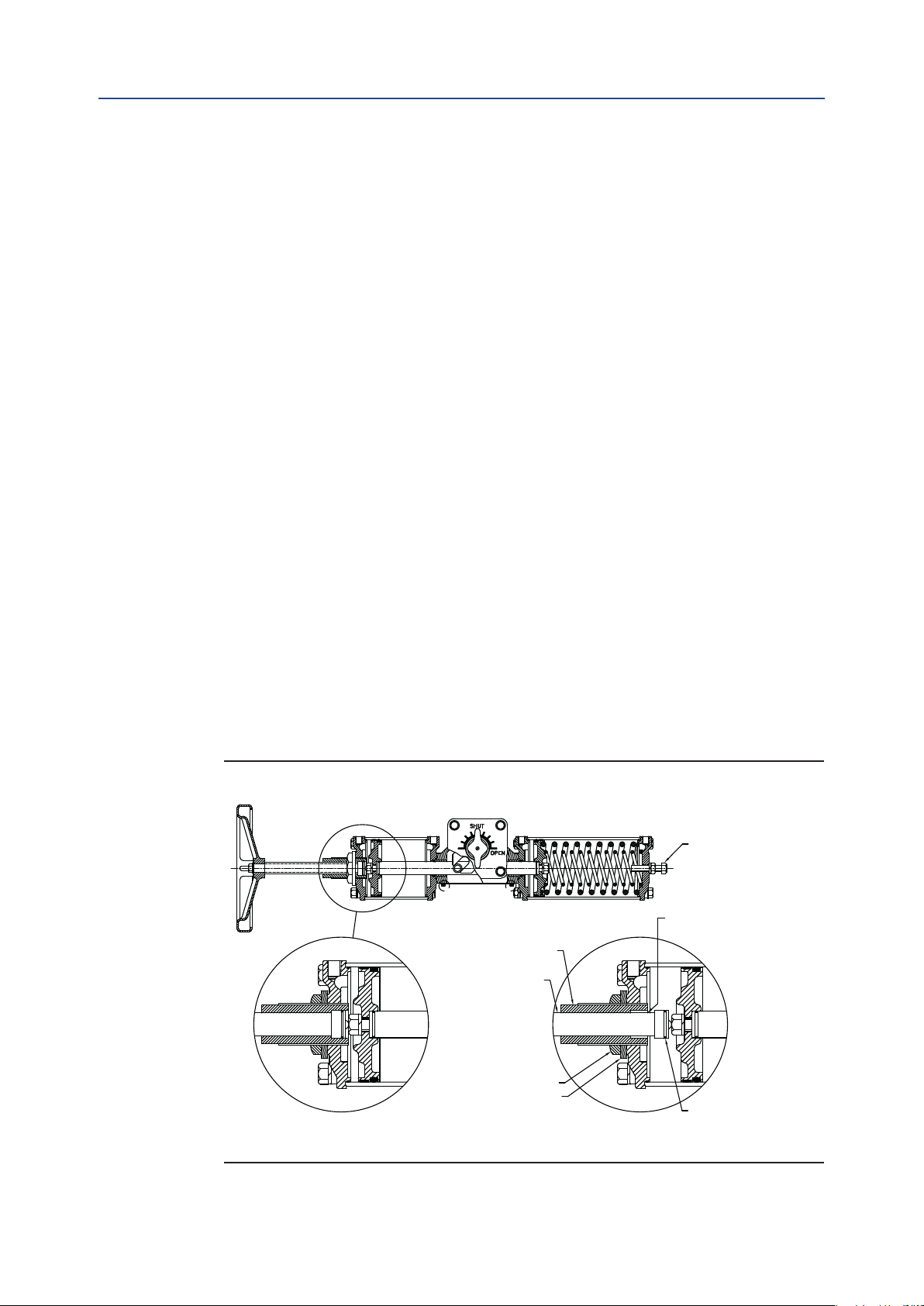
The jackscrew has a built-in actuator stroke adjustment, see Figure 3 and 4.
3.3 Models 006 through 270
See Figure 3:
1. Retract the jackscrew override completely by rotating counter clockwise.
2. Loosen the lock nut and turn the brass adjusting screw to the desired position.
The handwheel will rotate with the adjusting screw. Never make stroke
adjustments by turning the handwheel only.
3. Tighten lock nut.
Figure 3 Jackscrew Override - Models 006 through 270
Stroke adjusting screw
Actuator stroke
adjusting screw
Note: Air escapes unless
jackscrew is fully retracted
Jackscrew
Lock nut
Seal
JACKSCREW FULLY RETRACTED JACKSCREW EXTENDED
4
Jackscrew seal
Jackscrew Override

Installation, Operation and Maintenance Manual
Section 3: Jackscrew Override
MAN-02-01-39-0704-EN Rev. 1 May 2020
3.4 Models 370, 740 and 575
See Figure 4:
1. Retract the jackscrew override completely by rotating clockwise.
2. Loosen the stroke adjusting screw and lock nut.
3. Using the handwheel, turn the jackscrew to adjust the actuator to the
desired position.
4. Screw the adjusting screw until it stops and tighten lock nut.
Figure 4 Jackscrew Override - Models 370, 575 and 740
Handwheel
Lock nut
Stroke
adjusting
screw
Sealed jackscrew
assembly
SHUT
OPEN
OPEN
SHUT
Lock nut
Stroke adjusting screw
Jackscrew Override
5
38
27
46
4
51545049565553132264462738
38
27
46
4
Section 3: Jackscrew Override
May 2020
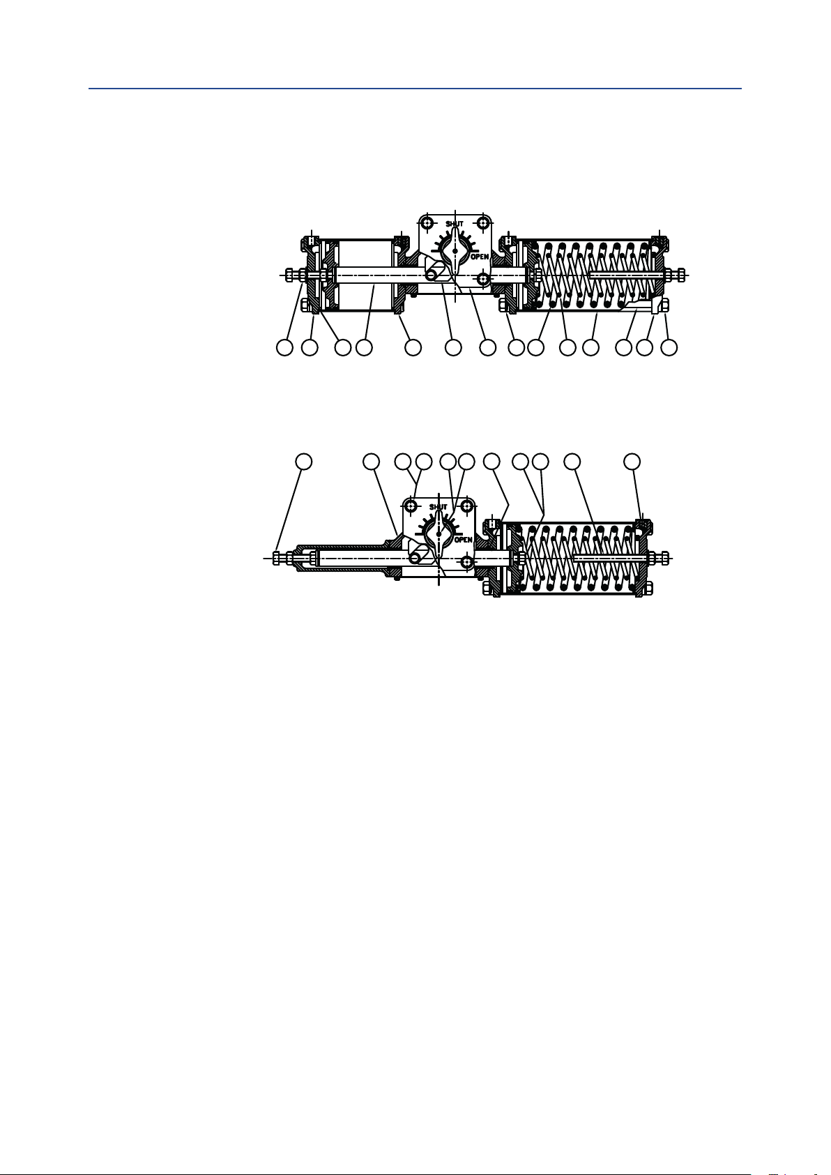
Single-Acting Spring-Return Two Pistons
Models: 012, 046, 058, 059, 072, 100, 144, 270, 344, 345, 420, 740, 944, 945, 1150,
1480, 1929, 1930, 2380
Single-Acting Spring-Return One Piston
Models: 006, 015, 023, 036, 050, 135, 210, 370 and 575
Installation, Operation and Maintenance Manual
MAN-02-01-39-0704-EN Rev. 1
51545049565553132264462738
37 1 14 15 17 21 33 34 52 57
8a
6
Jackscrew Override
 Loading...