

Installation, Operation, and Maintenance Manual: FieldQ Actuator Release 2 (Current)
Table of contents
 Loading...
Bettis Installation, Operation, and Maintenance Manual: FieldQ Actuator Release 2 (Current) Manuals & Guides
Page 1

Installation, Operation and Maintenance Manual
FieldQ
Pneumatic Actuators with Integrated Controls
DOC.IOM.Q.E Rev. D
April 2019
FieldQ
Page 2

Page 3

Installation, Operation and Maintenance Manual
DOC.IOM.Q.E Rev. D
Table of Contents
Section 1: Before You Start
1.1 Installation, Operation and Maintenance Reference Documents .................... 1
1.2 Warehouse Storage ....................................................................................... 2
1.3 On-Site Storage ............................................................................................. 2
Section 2: Introduction
2.1 Identication ................................................................................................. 3
2.2 Intended Use .................................................................................................5
2.3 Specications ................................................................................................ 5
Section 3: Configuration Code
Table of Contents
April 2019
Section 4: Installation
4.1 Before You Start ............................................................................................ 9
4.2 Actuator Rotation Direction .......................................................................... 9
4.2.1 Valve Rotation .................................................................................... 9
4.2.2 Position After Failure ........................................................................ 10
4.3 Principles of Operation ................................................................................ 11
4.3.1 Solenoid Valve Operation / NAMUR Adaptation Plate ........................ 11
4.3.2 Ingress Protection (IP) Rating ........................................................... 12
4.3.3 Control Module Operation................................................................12
4.3.4 Double-Acting Operation with Fail-In-Last Position Function ............ 14
4.3.5 Spring-Return Actuators ................................................................... 16
4.3.6 Position Feedback ............................................................................ 18
4.4 Actuator Assembly Codes ........................................................................... 19
4.5 Actuator to Valve Installation ...................................................................... 21
4.6 Mounting of Control Modules or Generic Control and Feedback Accessories ..... 24
4.7 Recommended Tubing Sizes ........................................................................ 24
Section 5: Mechanical Stroke Adjustment
5.1 Travel Stop Adjustment ............................................................................... 26
5.1.1 Double-Acting Actuators .................................................................. 26
5.1.2 Spring-Return Actuators ................................................................... 27
5.1.3 Angular Displacement ...................................................................... 28
Section 6: Maintenance
6.1 Normal Maintenance ................................................................................... 29
6.2 Inspection and Repair .................................................................................. 30
6.2.1 Service Kits ....................................................................................... 30
6.2.2 Spring-Return Actuator .................................................................... 30
Section 7: Decommission (Out of Service)
7.1 Before You Start .......................................................................................... 31
7.2 Removing the Actuator from the Valve ........................................................ 32
ITable of Contents
Page 4

Table of Contents
April 2019
Section 8: Disassembly
Section 9: Reassembly
Installation, Operation and Maintenance Manual
DOC.IOM.Q.E Rev. D
8.1 Removing End Caps (Size 40 to 600)............................................................ 34
8.2 Removing End Caps (Size 950 to 1600) ....................................................... 36
8.3 Removing Spring Cartridges or Springs ....................................................... 37
8.4 Removing of Limit Stop Screws ................................................................... 38
8.5 Removing Pistons ........................................................................................38
8.6 Removing Pinion ......................................................................................... 39
8.7 Cleaning the Components .......................................................................... 40
9.1 Grease Instructions ..................................................................................... 42
9.2 Reassembly of the Pinion ............................................................................. 43
9.3 Reassembly of the Pistons ........................................................................... 44
9.4 Reassembly and Settings of the Limit Stops ................................................. 46
9.5 Reassembly of the End Caps ........................................................................ 47
9.5.1 Double-Acting Actuators .................................................................. 47
9.5.2 Spring-Return Actuators (Size 40 to 600) ..........................................48
9.5.3 Spring-Return Actuators (Size 950 to 1600) ......................................50
9.6 Basic Function and Air Leak Test .................................................................. 52
Section 10: Troubleshooting
10.1 Mechanical Problems .................................................................................. 53
10.2 Pneumatic Problems ................................................................................... 54
10.3 Electrical Problems ...................................................................................... 55
Section 11: Parts List and Spare Parts Recommendations
11.1 Actuator Size Q40 to Q600 .......................................................................... 56
11.2 Actuator Size Q950 to Q1600 ...................................................................... 57
Appendix A: Spring Load Removal
A.1 Spring Load Relief ........................................................................................ 58
Appendix B: Tool & Torque Table
Appendix C: Full Stroke Adjustment Option
C.1 Full Stroke Adjustment Option .................................................................... 62
C.2 Convert a Standard Actuator into a Full Stroke Adjustment Version ............. 63
11.2.1 Procedure ........................................................................................64
C.3 Full Stroke Adjustment Setting .................................................................... 65
11.2.2 Factory Setting Procedure ................................................................ 65
11.2.3 Setting the Full Stroke Adjustment Screw to the Required Angle....... 66
II
Table of Contents
Page 5

Installation, Operation and Maintenance Manual
DOC.IOM.Q.E Rev. D
Section 1: Before You Start
This section explains:
• Base safety procedures.
• Where to nd detailed information relating safety.
• Storage guidelines.
Installation, adjustment, putting into service, use, assembly, disassembly and maintenance
of the pneumatic actuator must be performed by qualied personnel.
NOTICE
Failure to follow the above guidelines will void warranty.
WARNING
Section 1: Before You Start
April 2019
Actuator must be isolated both pneumatically and electrically before any (dis)assembly starts.
Before mounting or (dis)assembly, the actuator consult the relevant sections of this manual.
1.1 Installation, Operation and Maintenance Reference Documents
Before you start, read the following documents:
• All Sections in this manual.
• Safety Guide (Document No. DOC.SG.FQ.EN).
Mounted Control modules are shipped with the applicable installation guide:
QC41, QC42 or QC43: Document DOC.IG.QC41.1.
QC40: Document DOC.IG.QC40.1.
QC54: Document DOC.IG.QC54.1.
For Safety Instrumented Systems application, read the following document:
• SIL Safety Manual FieldQ (Document No. DOC.SILM.FQ.EN).
Before You Start
NOTICE
Failure to read the Safety Guide will void the warranty.
Not following the instructions of the Safety Guide can lead to failure of the product and
harm to personnel or equipment.
1
Page 6

Section 1: Before You Start
April 2019
Installation, Operation and Maintenance Manual
1.2 Warehouse Storage
• All actuators should be stored in a clean, dry warehouse, free from excessive
vibration and rapid temperature changes.
• All actuators should not be stored directly to the oor surface - it must be placed in
racks/shelves or use a pallet.
1.3 On-Site Storage
• All actuators should be stored in a clean, dry warehouse, free from excessive
vibration and rapid temperature changes.
• Prevent moisture or dirt from entering the actuator. Plug or seal both air
connection ports.
NOTICE
Failure to follow the above guidelines (Warehouse and On Site Storages) will void warranty.
DOC.IOM.Q.E Rev. D
Before You Start2
Page 7

Installation, Operation and Maintenance Manual
DOC.IOM.Q.E Rev. D
Section 2: Introduction
This section explains:
• How to identify the received product.
• The intended use of the product.
• Construction details.
• Actuator specications.
2.1 Identification
The FieldQ Rack and Pinion actuators are available as double-acting or spring-return
versions. 13 models are available, ranging from 40 Nm to 1600 Nm (354 to 14161 lbf.in)
nominal torque output.
The FieldQ package consists of an actuator with a module for control and position feed
back and forms an integrated concept for “On/Off” valve automation.
Section 2: Introduction
April 2019
1. Basic Actuators
The basic actuator supplies the torque, required to open and close valves and is
available in various sizes (rated 47 to 1676Nm at 5.5barg or 413 to 14874 In.lb. at 80pisg).
Double acting and spring return executions are available. The spring return execution can be
equipped with multiple spring sets to cover a pressure range from 2 to 8 barg (30 to 120 psig).
The springs in the spring-return version allow a fail action in case of loss of air supply
pressure (Fail-to-Close or Fail-to-Open). As from size FD150 double-acting versions have
at end caps to reduce actuator length and internal air volume.
The springs in the spring-return version allow a fail action in case of loss of air supply
pressure (Fail-to-Close or Fail-to-Open).
As from size 150 double-acting versions have at end caps to reduce actuator length and
internal air volume.
2. Control Modules
The Control Modules contain, next to the components for feedback switches, also all the
pneumatic control components.
Its compact and robust construction incorporates basic control and feedback functionality
and is suitable for indoor and outdoor use.
3. NAMUR Adaptation Plate
The top ange of the FieldQ actuator is equipped with a NAMUR (VDE/VDI 3845) drilling
pattern. The addition of a NAMUR plate makes the FieldQ actuator suitable for mounting
all kinds of NAMUR compatible control accessories like solenoids. For more info on NAMUR
plate, see sheet 1.605.03.
Introduction
3
Page 8
Section 2: Introduction
e
April 2019
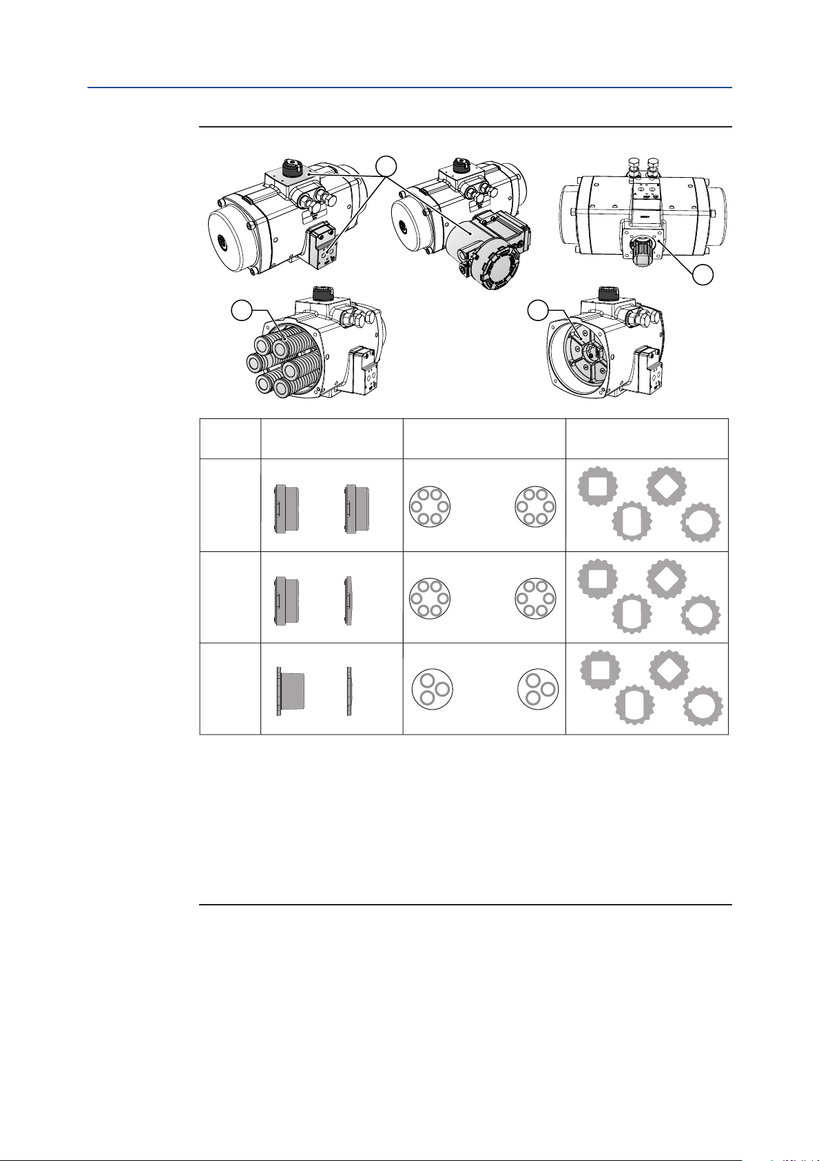
Figure 1 Identification
Installation, Operation and Maintenance Manual
DOC.IOM.Q.E Rev. D
1
2
3 4
Size End cap design
SR DA
5
Spring design
Left
6
Right
Pinion bottom /
Insert design
2
40 100
Maximum 12
spring cartridges
SR Left RightDA
150 -
600
Maximum 12
spring cartridges
Left RightSR DA
950 -
1600
Notes:
1. Top auxilliaries according (VDI/VDE 3845; NAMUR). FieldQ comes with a proprietary pneumatic interface
for direct mounting of the Control modules. Option: NAMUR adaptation plate for direct mounting of solenoids.
2. Valve interface available according ISO5211 or DIN 3337. Actuator sizes 40 to 1600 can be fitted with driv
inserts with various inner shapes.
3. Spring-Return actuators: - with springs
4. Double-Acting actuators: - no springs
5. Actuator sizes 40 to 100 have high end caps for double-acting and spring-return models. Actuator sizes
150 to 1600 have low end caps for double-acting models and high end caps for spring-return models.
6. Actuator sizes 40 to 600 are fitted with a maximum of 12 spring cartridges. Actuator sizes 950 and 1600
are fitted with a maximum of 6 loose springs.
Maximum 6
loose springs
Introduction4
Page 9

Installation, Operation and Maintenance Manual
DOC.IOM.Q.E Rev. D
2.2 Intended Use
The FieldQ Rack and Pinion actuators are intended for the automation and operation of
quarter-turn valves like Buttery, Ball and Plug valves.
Rack and Pinion actuators can also be used to operate dampers or any other quarter-turn
applications.
2.3 Specifications
Table 1. Pressure Range
Actuator Type Pressure
Double-Acting 0.2 to 8.3 barg (2.9 to 120 psig)
Spring-Return
6 to 8.3 barg (87 to 120 psig), with maximum spring set
3 to 8.3 barg (43.5 to 120 psig), reduced spring quantity
Section 2: Introduction
April 2019
Table 2. Operating Media
Actuator Type Operating Media
Air, dry or lubricated and inert gases
Dew point at least 10K below ambient temperature
Double-Acting and Single-Acting
1. For the base actuator the recommended air quality for normal operation
(according ISO 8573-1) is: 7-5-4.
2. In case Q-Series Control Modules are used, the operating media specication as mentioned in
the Installation Guide (shipped with each control module) are applicable.
QC41, QC42 or QC43: Document DOC.IG.QC41.1.
QC40: Document DOC.IG.QC40.1.
QC54: Document DOC.IG.QC54.1.
For sub-zero applications, take appropriate measures
Mentioned pressure levels are "gauge pressures".
Gauge pressure is equal to absolute pressure minus
atmospheric pressure.
NOTE:
Use of lters, pressure regulators, lubricator and an oil/water separator mounted in the air
supply line, will allow a smooth and durable operation of the actuator.
For lubricated supply air, it is recommended to use a non-detergent oil without aggressive
additives, VG32, group 2 (ISO 3448).
Table 3. Temperature Range
Introduction
Actuator Type Temperature
Standard -20°C to +80°C (-4°F to +176°F)
Option: Low Temperature -40°C to +80°C (-40°F to +176°F)
Option: High Temperature -10°C to +120°C (+14°F to +250°F)
1. In case Q-Series Control Modules are used, the temperature range as mentioned in
the Installation Guide (shipped with each control module) are applicable.
QC41, QC42 or QC43: Document DOC.IG.QC41.1.
QC40: Document DOC.IG.QC40.1.
QC54: Document DOC.IG.QC54.1.
5
Page 10
A
B
Section 2: Introduction
April 2019
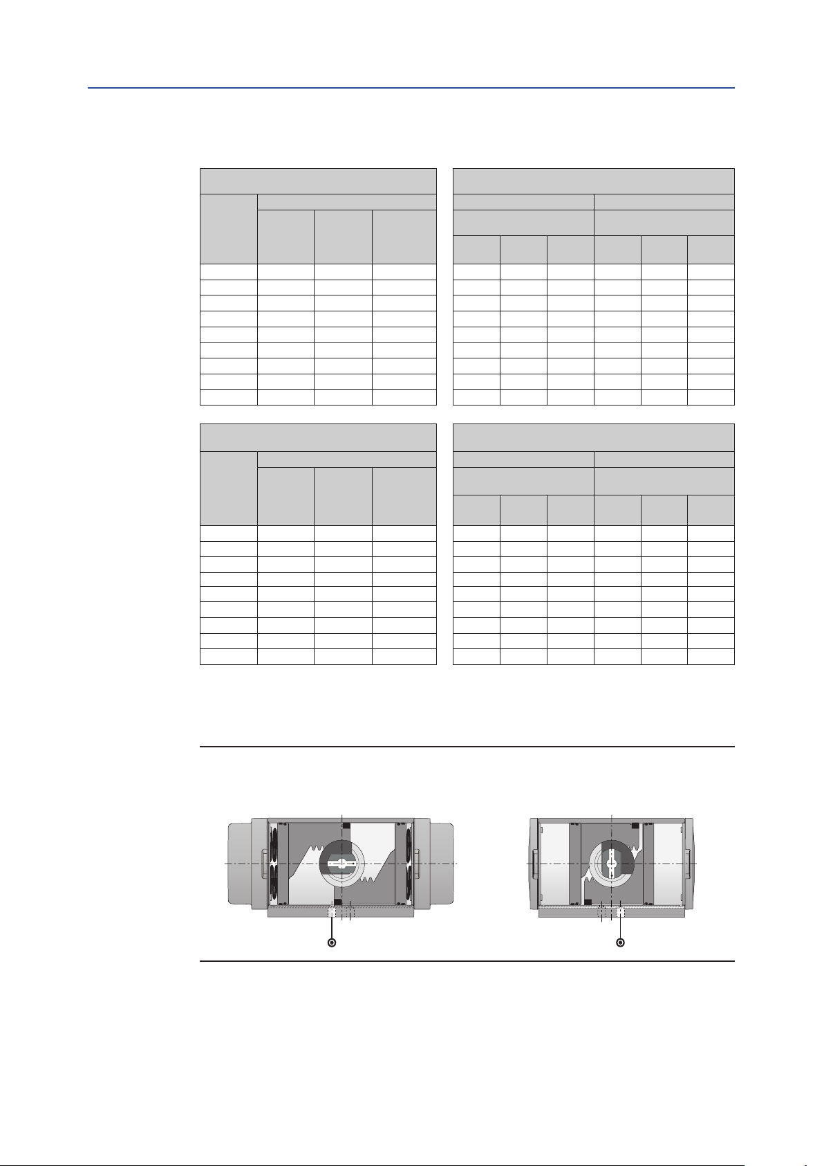
Table 4. Air Volumes and Consumption
Actuator
model
Q 0040 0.26 0.37 0.15 0.67 1.2 2.2 0.89 1.6 3.1
Q 0065 0.40 0.56 0.22 1.02 1.8 3.4 1.3 2.4 4.7
Q 0100 0.6 0.9 0.3 1.5 2.7 5.0 2.0 3.8 7.2
Q 0150 1.0 0.8 0.5 2.4 4.3 8.1 2.1 3.6 6.7
Q 0200 1.3 1.0 0.7 3.2 5.7 11 2.8 4.9 9.1
Q 0350 2.1 1.9 1.2 5.5 9.8 18 5.0 8.8 16
Q 0600 3.6 3.3 2.1 9.4 17 31 8.7 15 28
Q 0950 4.9 4.6 3.2 13 23 43 12 22 40
Q 1600 7.9 7.3 5.4 21 37 69 20 35 64
Installation, Operation and Maintenance Manual
DOC.IOM.Q.E Rev. D
Actuator volumes:
Maximum volume (in liters) Outward Stroke Inward Stroke
Double-Acting
and Spring-Return
2.0 barg 4.0 barg 8.0 barg 2.0 barg 4.0 barg 8.0 barg
Central
chamber
1
End cap
chamber
2
Displaced
volume
3
Consumption per stoke
(in liters, pressure in barg)
Double-Acting only
Actuator volumes:
Maximum volume (Cu.in.) Outward Stroke Inward Stroke
Actuator
model
Q 0040 15.9 23 8.9 53 96 140 71 133 196
Q 0065 24 34 13.5 81 148 215 107 200 294
Q 0100 36 53 19.9 118 216 314 165 310 455
Q 0150 58 47 32 192 352 512 163 293 424
Q 0200 76 64 44 255 466 676 220 397 573
Q 0350 131 115 76 436 796 1157 392 709 1025
Q 0600 222 201 129 742 1354 1967 683 1237 1790
Q 0950 301 279 196 1025 1854 2682 966 1735 2505
Q 1600 484 447 328 1662 2997 4331 1560 2792 4024
Central
chamber
1
End cap
chamber
2
Displaced
volume
3
Double-Acting
and Spring-Return
40 psig 80 psig 120 psig 40 psig 80 psig 120 psig
Consumption per stoke
(in Cu.in., pressure in psig)
Double-Acting only
Notes:
1. Pistons at 90° outward position.
2. Pistons at 0° inward position.
3. Stroke is 90°.
Figure 2 Actuator Air Volumes
Central air chamber volume
Double-Acting and Spring-Return
End cap air chamber volume
Double-Acting only
6
Introduction
Page 11

Installation, Operation and Maintenance Manual
DOC.IOM.Q.E Rev. D
Section 3: Conguration Code
This section explains:
• How to create or read the conguration code for a actuator.
QS 0150 - N U 40 CW AL TN - L17 S K A - 00 XX
Section 3: Configuration Code
April 2019
Miscellaneous options
Internal code 1
Color / nish
Visual indicator
Temperature
Valve stem connection
Valve interface
Pinion material
Rotation
Spring set
Threads
Rotation angle
Size
Typ e
Typ e
FD Double Acting
FS Spring Return
Size
0040 Size 0040 0350 Size 0350
0065 Size 0065 0600 Size 0600
0100 Size 0100 0950 Size 0950
0150 Size 0150 1600 Size 1600
0200 Size 0200
Rotation Angle
N 90° rotation angle
Threads
M Metric ISO 5211
U UNC/NPT/Imperial
Spring Set
00 Double Acting (no springs)
10 Spring Set 10 40 Spring Set 40
20 Spring Set 20 50 Spring Set 50
30 Spring Set 30 60 Spring Set 60
Rotation Direction
CW Spring to Close/Clock Wise
CC Spring to Open/Counter Clock Wise
Pinion Material
AL High Grade Aluminium, Hard anodized
Valve Interface, Note 2
TN Standard ISO 5211 interface
SY Small interface with center plate (DIN3337)
LY Large interface with center plate (DIN3337)
Notes:
See next page.
Valve Stem Connection, Note 3
Actuator Size
No insert 000
0040 & 0065 14mm / 0.551" L14 D14
0100
0150
0200 22mm / 0.866" L22 D22
0350
0600 27mm / 1.063" L22 D22
0350
0600 27mm / 1.063" L27 D27
0950 36mm / 1.417" L36 D36
1600 46mm / 1.811" L46 D46
Temperature Range
S Standard: -20°C to +80°C (-4°F to +176°F)
H High: -20°C to +120°C (-4°F to +248°F)
L Low: -40°C to +80°C (-40°F to +176°F)
Visual Indication Code
K Standard (Knob)
N No Visual Indication
Finish
A Standard coating (FieldQ Yellow)
Internal Code 1
00 Standard
Miscellaneous Options
XX Standard: Suitable for Control module mounting
N1 NAMUR adaptator plate
H1 NAMUR adaptator plate + 1/2" High Flow plate
FS Full stroke adjustement (only sizes 40 to 600)
NF NAMUR adaptator plate + Full stroke adjustment option
Square
Dimensions
17mm / 0.669" D17
19mm / 0.748" L19
17mm / 0.669" D17
19mm / 0.748" L19
22mm / 0.866" D22
27mm / 1.063" L27
22mm / 0.866" D22
27mm / 1.063" L27
Parallel
Drive
Diagonal
Drive
Conguration Code
7
Page 12

Section 3: Configuration Code
April 2019
Notes:
1. The options, listed here, are all options available. Not all options apply to all
congurations. Check the actuator size page for valid congurations.
2. Valve Interface:
— Option "S"; Small Interface with Center Plate (DIN3337)
— Option "L"; Large Interface with Center Plate (DIN33337)
3. Contact your local FieldQ representative for additional insert options.
4. PED Group 1 Label only available up to size 950.
Installation, Operation and Maintenance Manual
DOC.IOM.Q.E Rev. D
is not available for sizes 0950.
is not available for sizes 1600.
8
Conguration Code
Page 13
Installation, Operation and Maintenance Manual
DOC.IOM.Q.E Rev. D
Section 4: Installation
This section explains:
• The actuator rotation direction.
• In which position the actuator will end after a failure.
• Principles of operation:
— Solenoid operation.
— Double acting and Spring return operation.
• Assembly codes.
• Actuator to valve assembly.
4.1 Before You Start
Section 4: Installation
April 2019
SAFETY
In case of an air or electrical failure, it is important to know the behavior of the actuator.
Before mounting the actuator on a valve, consult the following sections below.
4.2 Actuator Rotation Direction
4.2.1 Valve Rotation
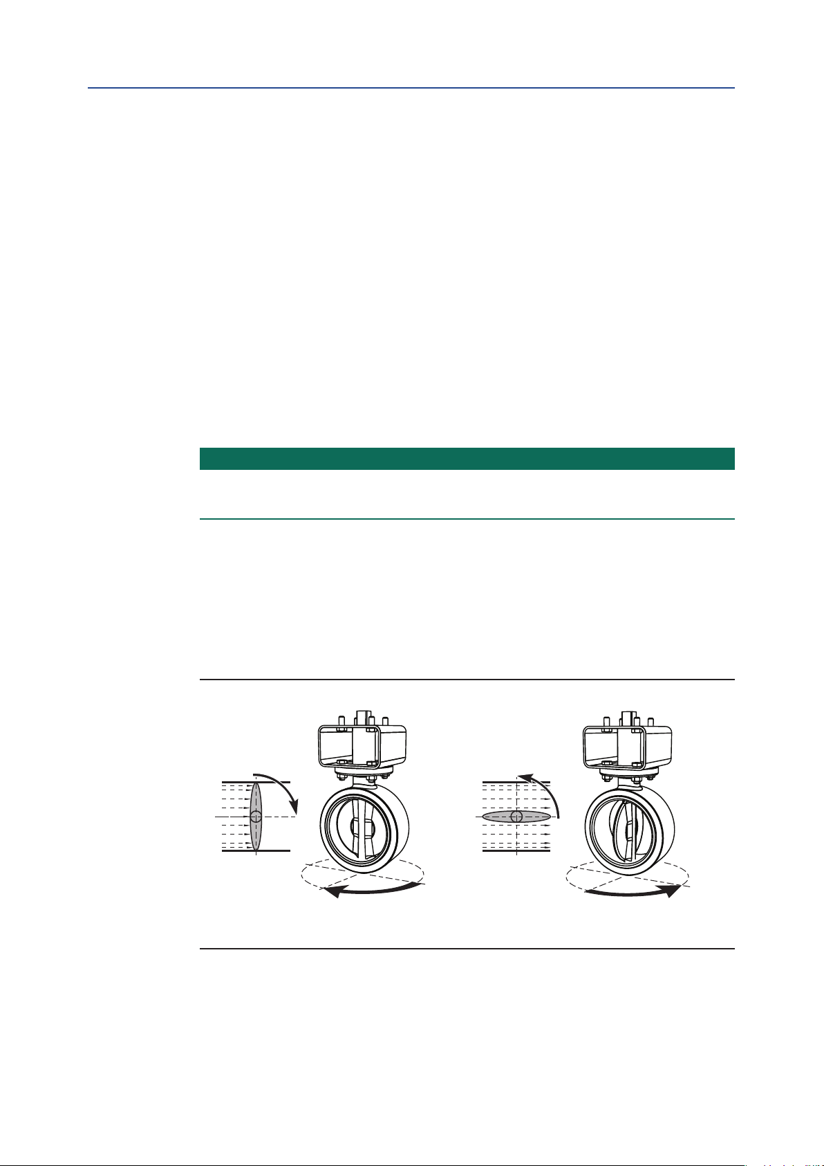
For the following paragraphs we assume that valves rotate as indicated in Figure 3.
Figure 3 Normal valve rotation
Installation
The valve is closed after
a clockwise rotation.
The valve is open after
a counterclockwise rotation.
9
Page 14
Section 4: Installation
April 2019
4.2.2 Position After Failure
The position of the actuator after a failure depends on the:
1. Principle of operation (see paragraph 4.3)
2. Assembly codes (see paragraph 4.4)
3. Kind of failure. Refer to the table below.
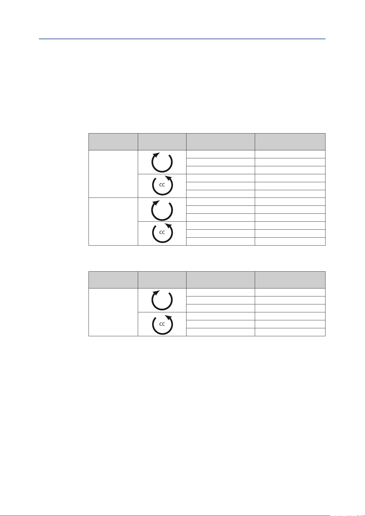
Table 5. Position After Failure
Installation, Operation and Maintenance Manual
DOC.IOM.Q.E Rev. D
Principle of
Operation
Double-Acting
Actuator
Single-Acting
(Spring-Return)
Actuator
Assembly Code Kind of Failure Position
Pressure Not dened
CW
CW
Signal Closed
Supply Voltage Closed
Pressure Not dened
Signal Open
Supply Voltage Open
Pressure Closed
Signal Closed
Supply Voltage Closed
Pressure Open
Signal Open
Supply Voltage Open
Table 6. Position after a failure with a Double-Acting module with
Fail-In-Last-Position Function
Principle of
Operation
Double-Acting
Actuator
Assembly Code Kind of Failure Position
Pressure Not dened
CW
Signal Not dened
Supply Voltage Closed
Pressure Not dened
Signal Not dened
Supply Voltage Open
10
Installation
Page 15
A
BA
Installation, Operation and Maintenance Manual
DOC.IOM.Q.E Rev. D
Section 4: Installation
4.3 Principles of Operation
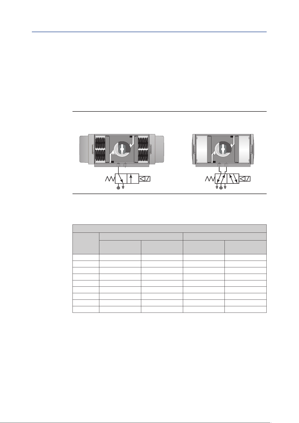
4.3.1 Solenoid Valve Operation / NAMUR Adaptation Plate
FieldQ actuators can be either piped with solid or exible tubing with the solenoid valve
mounted remotely from the actuator or by mounting a VDI/VDE 3845 (NAMUR) designed
solenoid valve DIRECTLY onto the NAMUR adaptation plate on the side of the actuator.
Figure 4 Typical Solenoid Operation
Spring-Return Operation Double-Acting Operation
April 2019
The table below represents the cycle time (operating time) per different Actuator sizes:
Table 7. Operating Speed
Cycle time in seconds
Actuator
size
Q 40 0.6 0.5 0.6 0.5
Q 65 0.7 0.5 0.6 0.6
Q 100 0.8 0.6 0.8 0.7
Q 150 1.0 0.8 0.9 0.8
Q 200 1.3 0.9 1.0 1.0
Q 350 1.9 1.3 1.4 1.5
Q 600 3.2 1.9 2.2 2.2
Q 950 6.6 2.2 2.4 2.0
Q 1600 10.6 3.5 3.6 3.3
Operating time is average with actuator under load and solenoid valve tted.
Test conditions:
1. Solenoid with ow capacity: 0.6 m3/hr
2. Pipe diameter: 6mm
3. Medium: clean air
4. Supply pressure: 5.5 bar (80psi)
5. Load: with average load
6. Stroke: 90°
7. Temperature: Room temperature
pressurized
Spring-Return Double-Acting
A-port
Spring
stroke
A-port
pressurized
B-port
pressurized
Installation
11
Page 16

Section 4: Installation
Installation, Operation and Maintenance Manual
April 2019
4.3.2 Ingress Protection (IP) Rating
FieldQ actuators are IP66 / NEMA4 rated. In case of IP66 or NEMA4 requirements, take
precautions that comply with the IP66 / NEMA4 requirements to prevent moisture or dust
from entering the actuator through the open air exhaust port(s), either directly on the
actuator or at the exhaust ports of the connected solenoid valve.
We recommend to connect tubing to the exhaust(s) and lead this into a dry and dust free
area, or to use check valves in the exhaust.
4.3.3 Control Module Operation
The operating principle, as explained here, is applicable for actuators with assembly code
CW (direct acting).
• The outward stroke will move the valve to the “Open” position.
• The inward stroke will move the valve to the “Closed” position.
• For assembly codes CC, the operating principle is reversed (reverse acting):
DOC.IOM.Q.E Rev. D
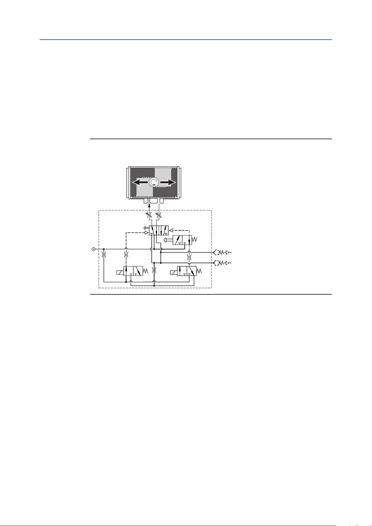
Figure 5 Double-Acting Operation
Outward Stroke
A-port
Option:
Throttle 1
5/2 Spool valve
Option: LMC
Ps
Pilot
valve 1
B-port
Option:
Throttle 2
Rb
Ra
1. Send control signal “Open” to the Control Module.
2. Pilot valve 1 will be activated and the 5/2spool valve will pressurize the central
air chamber.
3. The piston will move outwards to the “Open” position.
4. The Control Module indicates the “Open” position and activates feedback
signal “Open”.
12
Installation
Page 17

Installation, Operation and Maintenance Manual
DOC.IOM.Q.E Rev. D
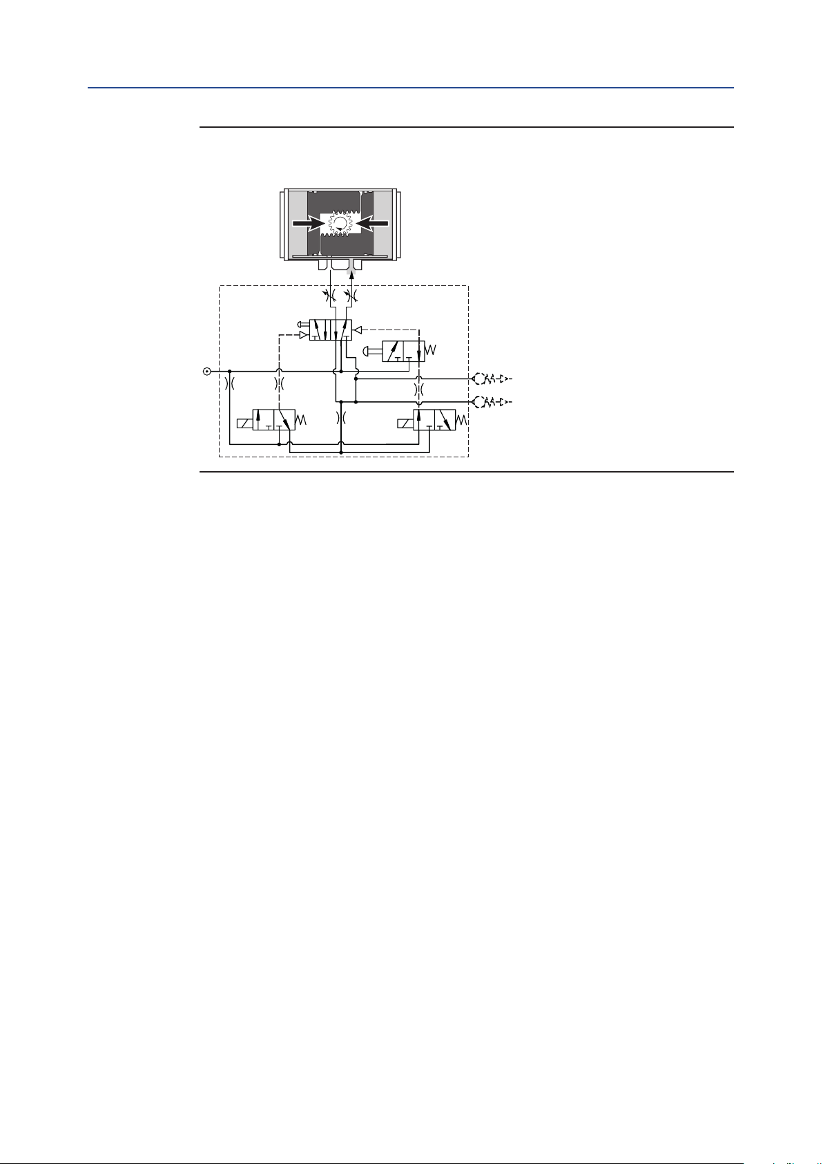
Figure 6 Double-Acting Operation
Inward Stroke
Section 4: Installation
April 2019
A-port
Option:
5/2 Spool valve
Option: LMC
Ps
Pilot
valve 1
Throttle 1
B-port
Option:
Throttle 2
Rb
Ra
1. Send control signal “Close” to the Control Module.
2. Pilot valve 1 will be deactivated and the 5/2 spool valve will pressurize the end cap
air chambers.
3. The piston will move inwards to the “Closed” position.
4. The Control Module indicates the “Closed” position and activates feedback
signal “Closed”.
Optional Controls:
LMC Local Manual Control
SC Speed Control throttles
Important
In case of an electric control signal failure, the actuator will move to its "Closed" position.
Installation
13
Page 18
Section 4: Installation
April 2019
Installation, Operation and Maintenance Manual
DOC.IOM.Q.E Rev. D
4.3.4 Double-Acting Operation with Fail-In-Last Position Function
The operating principle, as explained here, is applicable for actuators with assembly code
CW (direct acting).
• The outward stroke will move the valve to the “Open” position.
• The inward stroke will move the valve to the “Closed” position.
• For assembly codes CC the operating principle is reversed (reverse acting):
Figure 7 Double-Acting Operation with Fail-In-Last Position Function
Outward Stroke
B-port
Option:
Throttle 2
Pilot valve 2
Option:
LMC 2
Rb
Ra
Ps
Option: LMC 1
Pilot valve 1
A-port
Option:
Throttle 1
5/2 Spool valve
1. Send control signal “Open” to the Control Module to activate Pilot valve 1 and
de-activate Pilot valve 2.
2. The 5/2 spool valve will pressurize the central air chamber.
3. The piston will move outwards to the “Open” position.
4. The Control Module indicates the “Open” position and activates feedback
signal “Open”.
14
Installation
Page 19
Installation, Operation and Maintenance Manual
DOC.IOM.Q.E Rev. D
Figure 8 Double-Acting Operation with Fail-In-Last Position Function
Inward Stroke
Section 4: Installation
April 2019
A-port
Option:
Throttle 1
5/2 Spool valve
Option: LMC 1 Option: LMC 2
Ps
Pilot valve 1
B-port
Option:
Throttle 2
Pilot valve 2
Rb
Ra
1. Send control signal “Close” to the Control Module to activate Pilot valve 2 and
de-activate Pilot valve 1.
2. The 5/2 spool valve will pressurize the end cap air chambers.
3. The piston will move inwards to the “Closed” position.
4. The Control Module indicates the “Closed” position and activates feedback
signal “Closed”.
Optional Controls:
LMC Local Manual Control
SC Speed Control throttles
Installation
15
Page 20
Section 4: Installation
Installation, Operation and Maintenance Manual
April 2019
4.3.5 Spring-Return Actuators
The operating principle, as explained here, is applicable for actuators with assembly code
CW (direct acting).
• Applying supply pressure to port A will move the pistons outwards to the "Open"
position of the valve.
• Venting the supply pressure from port A will cause the springs to move the pistons
inwards to the "Close" position of the valve.
• For assembly codes CC, the operating principle is reversed (reverse acting):
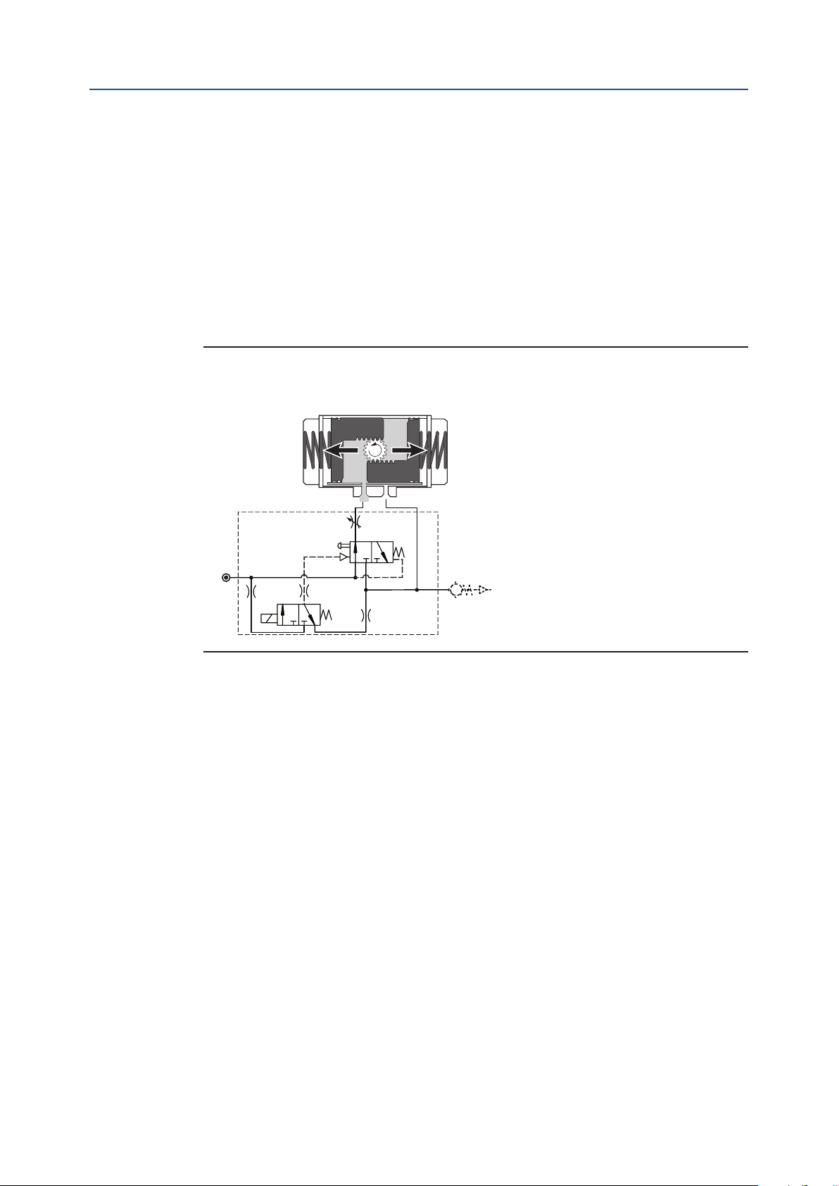
Figure 9 Single-Acting Operation
Outward Stoke
DOC.IOM.Q.E Rev. D
A-port
Option: Throttle 1
3/2 Spool valve
Option: LMC
Ps
Pilot
valve 1
B-port
Ra
1. Send control signal “Open” to the Control Module.
2. Pilot valve 1 will be activated and the 3/2 spool valve will pressurize the central
air chamber.
3. The piston will move outwards to the “Open” position.
4. The Control Module indicates the “Open” position and activates feedback
signal “Open”.
16
Installation
Page 21

Installation, Operation and Maintenance Manual
DOC.IOM.Q.E Rev. D
Figure 10 Single-Acting Operation
Inward Stroke
Section 4: Installation
April 2019
A-port
Option: Throttle 1
3/2 Spool valve
Option: LMC
Ps
Pilot
valve 1
B-port
Ra
1. Send control signal “Close” to the Control Module.
2. Pilot valve 1 will be deactivated and the 3/2 spool valve will vent the central
air chamber
3. The springs will move the pistons inwards to the “Closed” position.
4. The Control Module indicates the “Closed” position and activates feedback
signal “Closed”.
Optional Controls:
LMC Local Manual Control
SC Speed Control throttles
Installation
17
Page 22

Section 4: Installation
April 2019
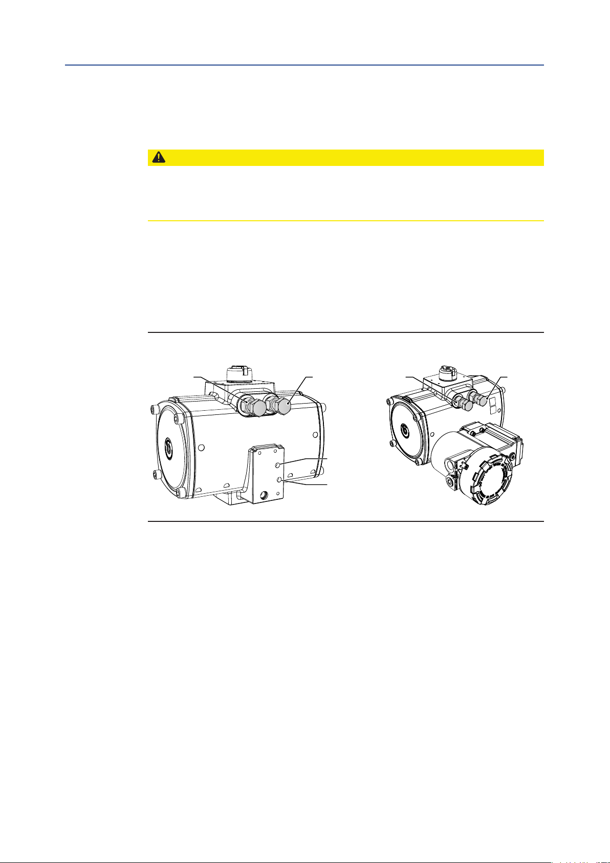
4.3.6 Position Feedback
The FieldQ Series actuator (1) has a patented, contact-less position sensing system.
This system consists of a position probe (2) which is rides on a special curve (4) in the
pinion bottom.
The curve is shaped in such a way that the position probe moves linearly and proportionally
to the rotation of the actuator pinion.
The linear movement of the position probe is used, inside the control module (3) to
operated the limit switches.
CAUTION
Do not put the Control module in direct contact with magnetic material. This can cause
damage or malfunction of the position feedback.
Installation of the FieldQ Series Control Modules
Installation, Operation and Maintenance Manual
DOC.IOM.Q.E Rev. D
Please refer to the Installation guides, as shipped with the product, for installation
instructions of the Control Module.
Installation Guides - Control modules
Each Control Module is shipped with an Installation Guide, which contains more
information on the pneumatic and electrical installation and operation of the Module.
Additionally, these Installation Guides can be downloaded from: www.emerson.com/eldq
Figure 11
1
3
2
4
18
Installation
Page 23
Si
Si
Installation, Operation and Maintenance Manual
DOC.IOM.Q.E Rev. D
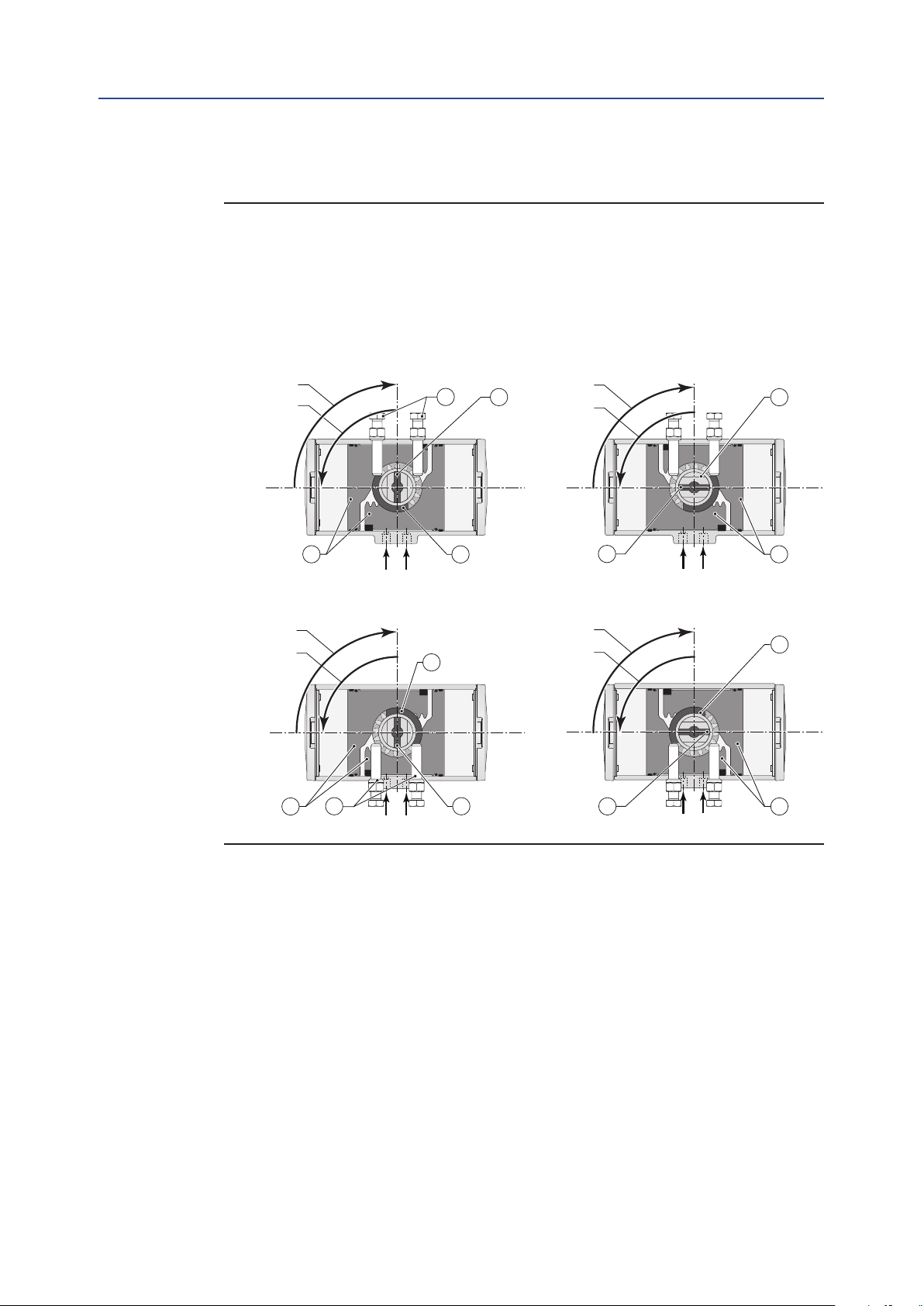
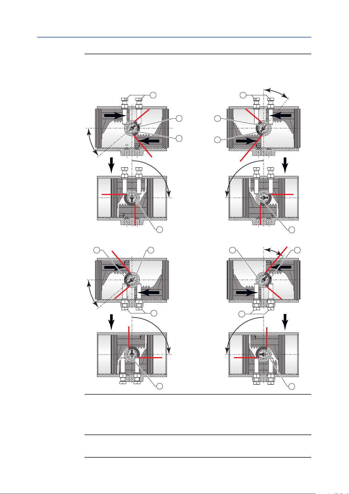
4.4 Actuator Assembly Codes
Figure 12 Assembly Code - Double-Acting
Assembly Code: CW Assembly Code: CC
= Standard, Clockwise-to-Close rotation = Reverse, Counterclockwise-to-Open
= Fail-to-Close = Fail-to-Open
zes Q40 and Q65
B
A
1
3
Section 4: Installation
April 2019
A
B
5
4
AB
zes Q100 to Q1600
B
A
4
1
AB
2
3
B
A
6
A
2
3
B
3
B
A
5
6
Rotation A = Central air chamber pressurized
Rotation B = End cap air chambers pressurized
1. Limit stops location
2. Position of cam
3. Position of slot and dot in pinion
4. Default pistons position
5. Pinion 90° Rotated
6. Reversed piston position
All views are from above. Pistons are shown in inward position.
Installation
19
Page 24

Section 4: Installation
April 2019
Figure 13 Assembly Code - Spring-Return
Assembly Code: CW Assembly Code: CC
= Standard, Clockwise-to-Close rotation = Reverse, Counterclockwise-to-Open
= Fail-to-Close = Fail-to-Open
Sizes Q40 and Q65
Installation, Operation and Maintenance Manual
DOC.IOM.Q.E Rev. D
B
A
1
3
A
B
5
4
Sizes Q100 to Q1600
B
A
4
1
AB
AB
2
7
3
A
2
3
7
B
3
Rotation A = Central air chamber pressurized
Rotation B = Spring stroke
1. Limit stops location
2. Position of cam
3. Position of slot and dot in pinion
4. Default pistons position
5. Pinion 90° Rotated
6. Reversed piston position
7. Springs
All views are from above. Pistons are shown in inward position.
6
B
A
5
B
A
6
20
Installation
Page 25
Installation, Operation and Maintenance Manual
DOC.IOM.Q.E Rev. D
4.5 Actuator to Valve Installation
WARNING: MOVING PARTS
Actuator must be isolated pneumatically and electrically before any (dis)assembly starts.
Stay away from moving parts to prevent serious injuries. When test cycling the actuator
and valve assembly by applying pressure to the actuator, be aware that there are moving
parts like pinion top, actuator to valve coupling and the valve- blade, ball, plug, etc.
NOTICE
The actuator is designed to be installed, commissioned and maintained using generic tools
like wrenches, Allen keys and screwdrivers. For the removal of inserts, a special extractor
tool can be supplied on request.
During assembly to the valve, do not hit with hammer on pinion top. This can damage the
pinion top washer and cause premature failure.
Section 4: Installation
April 2019
Before mounting the actuator on the valve or valve bracket, be sure that both the
actuator and the valve are in the same closed or open position.
Refer to appendix B, Tool and Torque tables, for using the right size tool and torque.
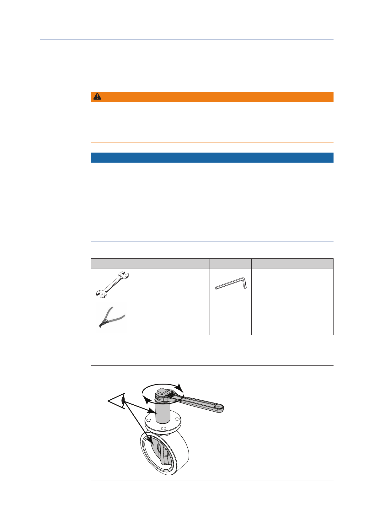
Table 8. Tool Table
Symbol Tool Symbol Too l
Wrench – All types and sizes.
Metric and Imperial
Circlip Pliers
1. Remove handle nut, handle, lock washer, and etc. from the valve if required.
2. Visually check to make sure the valve is CLOSED.
Figure 14 Valve Handle Removal
Allen key
Installation
21
Page 26

Section 4: Installation
April 2019
3. When required, check if the insert drive (23) is mounted. If not, use a plastic mallet
Figure 15 Insert Drive Installation
Installation, Operation and Maintenance Manual
DOC.IOM.Q.E Rev. D
and tap slightly until the insert is in the required position.
Be sure that the insert is mounted at 90° or 45°. It is possible to mount the insert
turned 22.5°. This way the valve will not open or close the right way.
90°
Parallel
square
45°
90°
Flat head
90°
23
Diagonal
square
4. Install the bracket to the valve ange. Tighten all bolts and nuts and apply the
correct torque.
Figure 16 Bracket Installation
Round with
key way
22
Installation
Page 27
Installation, Operation and Maintenance Manual
DOC.IOM.Q.E Rev. D
5. Install the actuator to the bracket. Tighten all bolts and apply the correct torque
(Refer to Table 9).
Table 9. Bottom Flange Torque Values
Section 4: Installation
April 2019
Actuator Size ISO Pattern
40, 65, 100
150, 200, 350
600
950
1600
F05 inner pattern M6 4.5 5.0 1/4"-20 3.3 3.7
F07 outer pattern M8 10.5 12.5 5/16"-18 7.7 9.2
F07 inner pattern M8 10.5 12.5 5/16"-18 7.7 9.2
F10 outer pattern M10 21.0 24.5 3/8"-16 15.5 18.1
F10 inner pattern M10 21.0 24.5 3/8"-16 15.5 18.1
F12 outer pattern M12 34.5 43.0 1/2"-13 25.4 31.7
F10 inner pattern M10 21.0 24.5 3/8"-16 15.5 18.1
F14 outer pattern M16 90.0 104.0 5/8"-11 66.4 76.7
F16 inner pattern M20 170.0 204.0 3/4"-10 125.4 150.5
F25* outer pattern 4x M16 90.0 104.0 4x 5/8"-11 66.4 76.7
Torque (Nm) Torque (lbf.ft)
Thread Min. Max. Thread Min. Max.
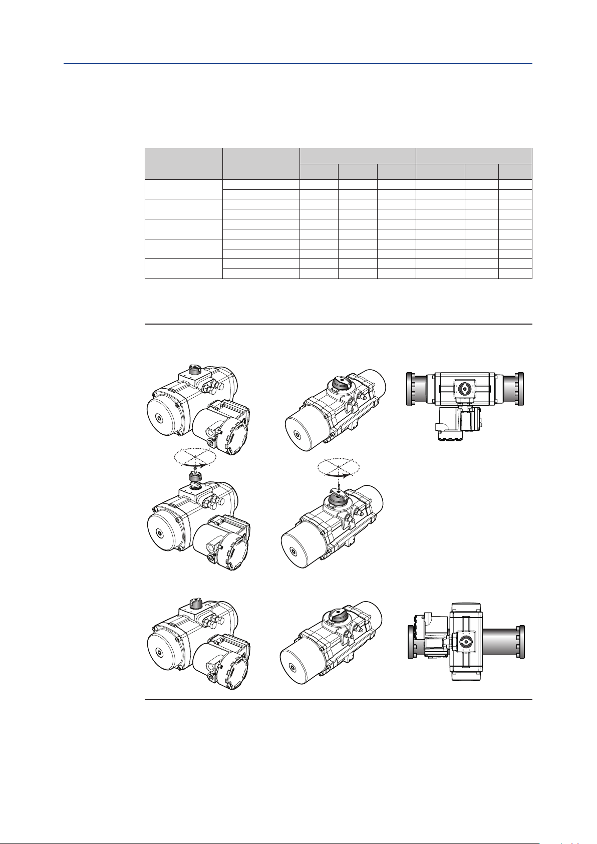
6. When required, mount or adjust the visual indicator (26).
Figure 17 Indicator Mounting
Size 950- 1600
Indicator Mounting “In-line”Size 40 - 600
90°
90°
Indicator Mounting “Across Line”
Installation
23
Page 28

Section 4: Installation
April 2019
Installation, Operation and Maintenance Manual
DOC.IOM.Q.E Rev. D
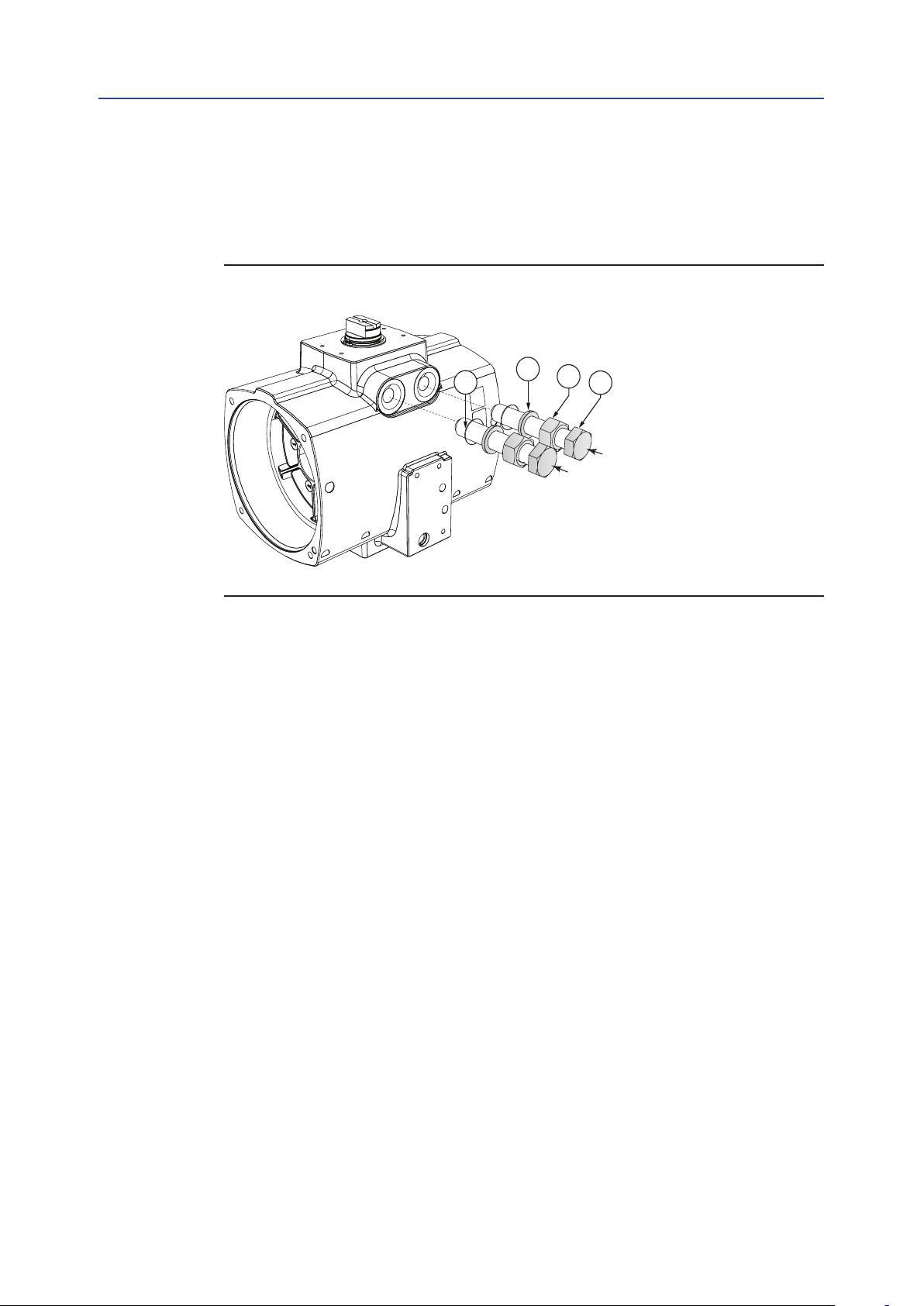
4.6 Mounting of Control Modules or Generic Control and Feedback Accessories
The base Q-Series actuator can be equipped with dedicated Q-Series Control modules or
generic controls and accessories.
1. Control modules are shipped with the applicable installation guide. Please refer
to below documents when the Contorl module needs to be mounted to the base
Q-Series actuator.
— QC41, QC42 or QC43: Document DOC.IG.QC41.1.
— QC40: Document DOC.IG.QC40.1.
— QC54: Document DOC.IG.QC54.1.
2. Solenoid valve and or switch boxes can now be mounted to the actuator.
Check the instructions as shipped with these components for installation,
operating and maintenance instructions. We recommend to test-cycle the
complete assembly to check correct operation.
4.7 Recommended Tubing Sizes
In case the solenoid valve is mounted remotely (i.e. in a central solenoid cabinet) and in
order to supply sufcient ow of air supply to the actuator, the following tubing sizes
are recommended.
Table 10. Tubing Sizes
Actuator size
40, 65 6 mm 1/4 inch 6 mm 1/4 inch
100, 150, 200,
350, 600
950, 1600 6 mm 1/4 inch 10 mm 3/8 inch
1.2 meters 4 feet 1.2 meters 4 feet
Runs up to Runs over to
6 mm 1/4 inch 8 mm 5/16 inch
24
Installation
Page 29
Installation, Operation and Maintenance Manual
DOC.IOM.Q.E Rev. D
Section 5: Mechanical Stroke Adjustment
Section 5: Mechanical Stroke Adjustment
This section explains:
• What mechanical stroke adjustment is.
• What the factory settings are.
• How to adjust the travel stops.
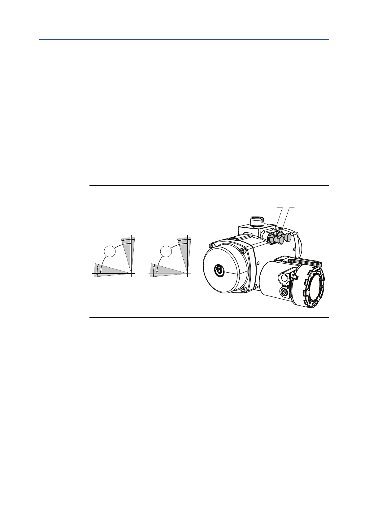
FieldQ actuator sizes 40 to 1600 have two stroke adjustment stops for adjusting accurately
the stroke of the actuator/valve assembly in open and closed position.
The factory setting of the stroke is 90°. Most quarter-turn valve applications will not require
readjustment of these settings.
If required the stroke can be adjusted by means of two-stroke adjustment bolts.
Figure 18 Factory Setting
April 2019
80°
95°
Open
Size 40 - 600
Closed
10°
90°
-5°
Size 950 - 1600
10°
90°
80°
93°
Open
Limit Stop 2Limit Stop 1
Closed
-3°
Mechanical Stroke Adjustment
25
Page 30
1S
Section 5: Mechanical Stroke Adjustment
April 2019
Installation, Operation and Maintenance Manual
5.1 Travel Stop Adjustment
CAUTION: PRESSURIZED ACTUATOR
Do not turn out the travel stops completely when the actuator is pressurized.
When adjusting the travel stops and the actuator is still pressurized, the travel stops can be
“shot” away when completely turned out.
5.1.1 Double-Acting Actuators
1. Operate valve/actuator assembly to the required "Closed" position.
2. Remove air supply.
3. Slacken locknut on the “Closed” stop (2).
DOC.IOM.Q.E Rev. D
Figure 19
Stop 1
4. Turn the “closed” stop clockwise to reduce or counterclockwise to increase the
travel. Consult Section 5.1.3 (angular displacement of the pinion), to dene how
far the limit stop must be turned in or out.
5. Tighten the lock nut.
6. Connect air and cycle the actuator to check that the position is correct.
If not repeat from 2.
7. Remove air supply.
8. For adjusting the open position repeat steps 1 to 7, but now for the open position
and “Open” stop (1).
Stop 2
A-port
B-port
Stop
top 2
26
Mechanical Stroke Adjustment
Page 31

1S
Installation, Operation and Maintenance Manual
DOC.IOM.Q.E Rev. D
5.1.2 Spring-Return Actuators
1. Connect air supply to the A port. Actuator will move to the open position.
2. Slacken locknut (24) on the “Closed” stop (2).
Figure 20
Section 5: Mechanical Stroke Adjustment
April 2019
Stop 1
Stop 2
Stop
top 2
A-port
B-port
3. Turn the “Closed” stop clockwise to reduce or counterclockwise to increase the
travel. Consult Section 5.1.3 (angular displacement of the pinion), to dene how
far the limit stop must be turned in or out.
4. Remove air supply. Actuator will move to the closed position.
5. Check whether the actuator valve assembly is in the required position.
If not repeat steps 1 to 5.
6. Remove air supply.
7. For adjusting the open position repeat steps 1 to 6, but now for the open position
and "Open" stop (1).
Table 11. Limit Stop Dimensions
Actuator size Thread
Q 40 M 8 13 13
Q 65 M 10 17 (16)* 17 (16)*
Q 100 M 10 17 (16)* 17 (16)*
Q 150 M 10 17 (16)* 17 (16)*
Q 200 M 12 19 (18)* 19 (18)*
Q 350 M 16 24 24
Q 600 M 20 30 30
Q 950 M 22 12 32
Q 1600 M 24 14 36
1. Default dimension according DIN933 standard.
2. Dimensions in brackets according ISO4017 standard.
Bolt Wrench Nut wrench
size (mm) size (mm)
Mechanical Stroke Adjustment
27
Page 32

Section 5: Mechanical Stroke Adjustment
April 2019
5.1.3 Angular Displacement
Below table identies, per actuator size, what the angular displacement of the pinions is,
when using the limit stop screws.
— Turn the limit stop clockwise reduces the stroke.
— Turn the limit stop counterclockwise to increase the stroke.
Table 12. Angular Displacement Limit Stops
Installation, Operation and Maintenance Manual
DOC.IOM.Q.E Rev. D
Actuator size
Q 40 0.8 6.3°
Q 65 0.6 8.3°
Q 100 0.7 7.1°
Q 150 1.2 4.2°
Q 200 1.0 5.0°
Q 350 0.8 6.3°
Q 600 0.8 6.3°
Q 950 1.1 4.7°
Q 1600 1.3 4.1°
Turns for 5° adjustment of the pinion: 360° revolution of limit stop screw will adjust
NOTICE
In case of air leakage over the limit stop bolts, turn the lock nut of the limit stop bolts
tighter, until leakage stops.
28
Mechanical Stroke Adjustment
Page 33

Installation, Operation and Maintenance Manual
DOC.IOM.Q.E Rev. D
Section 6: Maintenance
This section explains:
• When and how to do maintenance to the base actuator.
— Normal maintenance.
— Extraordinary maintenance.
• What to do when replacing springs.
• What the availability is of spare parts, action conversion kits and temperature
conversion kits.
WARNING
Actuator must be isolated pneumatically and electrically before any (dis)assembly starts.
Before mounting or (dis)assembling the actuator, consult the relevant sections of this manual.
Section 6: Maintenance
April 2019
6.1 Normal Maintenance
FieldQ actuators are designed to operate without maintenance for their normal working
life. Normal working life is 500,000 cycles* for sizes up to Q1600.
For actuators with the optional low temperature silicon seals, we advise to replace these
seals after 250.000 cycles*.
NOTE:
*Cycles = one open stroke and one close stroke.
We recommend regular inspections to make certain that the actuator / valve assembly
operates smoothly and to check that there are no visible or audible defects. We advise to
perform the following checks upon each proof test interval complying with the rules and
regulations of the country of nal installation:
• Visually check the entire actuator as well as the control system (where foreseen).
• Ensure there are no leaks on the actuator parts under pressure.
• Check pneumatic connections for leaks. Tighten tube ttings as required.
• Check if manual override (where foreseen) is regular.
Maintenance
• Check if pneumatic lter cartridge (where foreseen) is sound and lter bowl
(where foreseen) has been cleaned properly.
• Check the setting of the relief valves (where foreseen).
• Verify that the power uid supply pressure value is within the required range.
• Remove built-up dust and dirt from all actuator surfaces.
29
Page 34

Section 6: Maintenance
April 2019
• Inspect actuator paint work for damages to ensure continued corrosion protection.
Touch-up as required in accordance with the applicable paint specication.
• Operate the Actuator/Valve assembly for 2 complete open/close cycles with com-
plete closing of the valve.
• Verify the correct performing of open – close operations (e.g. check locally,
or automatically via Logic solver, the correct movement of the actuator).
All actuators are supplied with sufcient lubrication for their normal working life.
If required, see Section 9.1 (Grease instructions) for the recommended grease.
For mounting the parts of the repair kit follow the instruction of the Decommission,
Disassembly and Reassembly sections of this manual.
Installation, Operation and Maintenance Manual
6.2 Inspection and Repair
DOC.IOM.Q.E Rev. D
Replacement of internal seals and bearings allows to you extend the normal working
life. Service kits, containing all necessary spare parts (like seals, bearings, grease and
instructions) can be obtained through authorized Emerson – Actuation Technologies
distributors.
6.2.1 Service Kits
All soft seals, bearings, and nonreusable parts are included in the recommended service
kit. The service kit is identical for both the double-acting and the spring-return models.
6.2.2 Spring-Return Actuator
For the spring-return models, we recommend a set of spare springs for each different
model in addition to the recommended spare parts kit.
On spring-return actuators, the spring cartridges can be replaced. SPRING CARTRIDGES
SHOULD ALWAYS BE REPLACED IN COMPLETE SETS. Spring kits are available through
authorized Emerson – Actuation Technologies distributors.
30
Maintenance
Page 35

Installation, Operation and Maintenance Manual
DOC.IOM.Q.E Rev. D
Section 7: Decommission (Out of Service)
Section 7: Decommission (Out of Service)
This section explains:
• How to decommission an actuator in a safe way.
7.1 Before You Start
WARNING: MOVING PARTS
Actuator must be isolated pneumatically and electrically before any (dis)assembly starts.
Before mounting or (dis)assembling the actuator consult the relevant sections of this manual.
Actuator can move when removing supply pressure and/or electrical control signal of
actuators. If not already there, a spring-return actuator will cycle to its fail position.
When removing any ball valve or plug valve assemblies from a pipe system, isolate the
piping system on which the Actuator is installed and relieve any media pressure that may
be trapped in the valve cavities before removing the actuator for maintenance.
April 2019
A spring-return actuator mounted on a valve, which is stuck in mid stroke, contains a
high spring load which will cause a sudden rotation of the actuator versus the valve or
valve bracket during disassembly. This can cause serious injury to personnel or damage
to property.
Refer to Appendix A for instructions to safely remove the spring load before disassembling
the spring-return actuator from valve or bracket.
Important
Refer to the Safety Guide for Lifting Instructions.
Decommission (Out of Service)
31
Page 36
Section 7: Decommission (Out of Service)
April 2019
Installation, Operation and Maintenance Manual
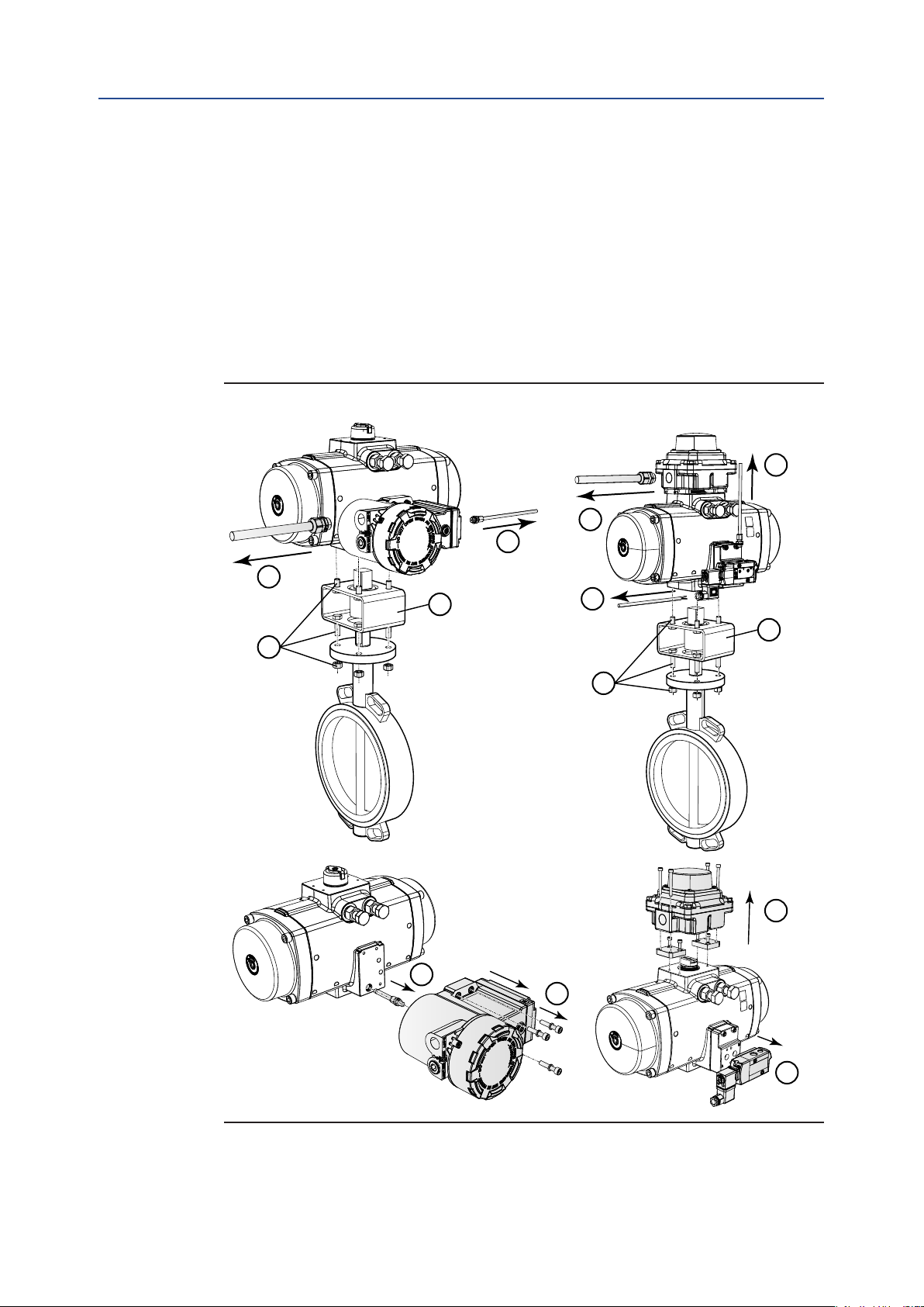
7.2 Removing the Actuator from the Valve
1. Disconnect all air supply hoses from the control module, ports A and B or solenoid.
2. Disconnect all electrical wirings of the Control module. or switch box or the
solenoid valve.
3. Remove the bolts and nuts from the valve ange.
4. Remove the bracket from the actuator.
5. Remove the switch box and solenoid valve. Refer to the documentation of the
switch box and solenoid valve for safe disassembly.
Figure 21 Removing Actuator from Valve
DOC.IOM.Q.E Rev. D
1
2
1
2
4
3
2
4
3
5
32
6
5
5
Decommission (Out of Service)
Page 37

Installation, Operation and Maintenance Manual
DOC.IOM.Q.E Rev. D
Section 8: Disassembly
This section explains:
• How to disassemble an actuator safely.
Tip
The instructions of this section can be used for maintenance or reconguration like spring
set change or maintenance.
Reference numbers for components refer to the exploded view in Section 11.
In case of maintenance, discard all the used soft parts like O-ring seals, guide bands,
wear strips and circlip.
WARNING
Actuator must be isolated pneumatically and electrically before any (dis)assembly starts.
Section 8: Disassembly
April 2019
Before mounting or (dis)assembling the actuator consult the relevant sections of this manual.
CAUTION: SPRING FORCE
Spring-return actuators contain springs in a compressed state. Follow these instructions to
release the spring force safely.
The end caps of spring-return actuators sizes 40 to 600 should be free of the spring load
after 10 full turns (crosswise relaxing) of the end cap screws. If there is still spring load on
the end cap, this might indicate a broken spring cartridge. Stop this disassembly procedure
immediately. Continuing might cause the end cap to be “shot” away causing serious injury.
Spring return actuator size 950 to 1600 have long end cap screws to release the spring load
safely.
Refer to Appendix A for instructions to safely remove the spring load before disassembling
the end cap of a spring-return actuator with a broken spring cartridge.
NOTICE
The actuator is designed to be installed, commissioned and maintained using generic tools
like wrenches, Allen keys and screwdrivers.
Refer to the tables in this section or refer to appendix B Tool and Torque tables.
Disassembly
33
Page 38
Section 8: Disassembly
April 2019
Installation, Operation and Maintenance Manual
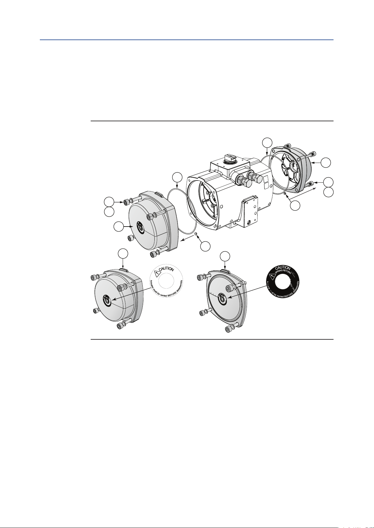
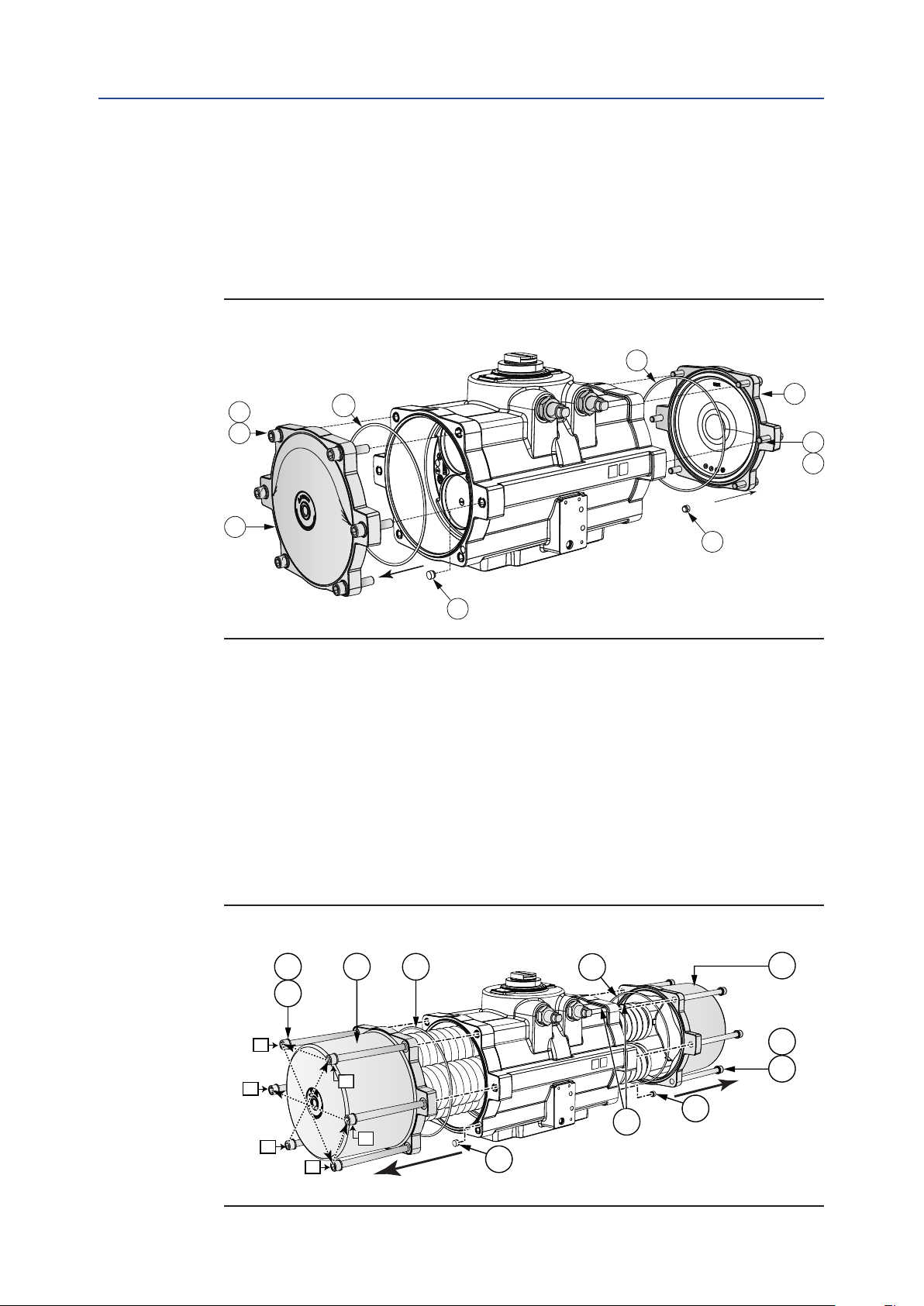
8.1 Removing End Caps (Size 40 to 600)
1. For Double-acting actuators, do the following:
a. Remove the screws (8) and washers (10) of the end caps (6).
b. Remove the o-ring (11) and "B" port seal (2). Discard these parts.
Figure 22 Double-Acting End Caps Removal
11
DOC.IOM.Q.E Rev. D
6
11
8
10
8
2
10
6
2
6
Double-Acting end caps (6) are fitted with a white warning sticker. Spring-Return end
caps (5) are fitted with a black warning sticker.
5
34
Actuator sizes 40 to 100 have high end caps for double-acting and spring-return models.
Actuator sizes 150 to 1600 have low end caps for double-acting models and high end
caps for spring-return models.
Disassembly
Page 39
Installation, Operation and Maintenance Manual
DOC.IOM.Q.E Rev. D
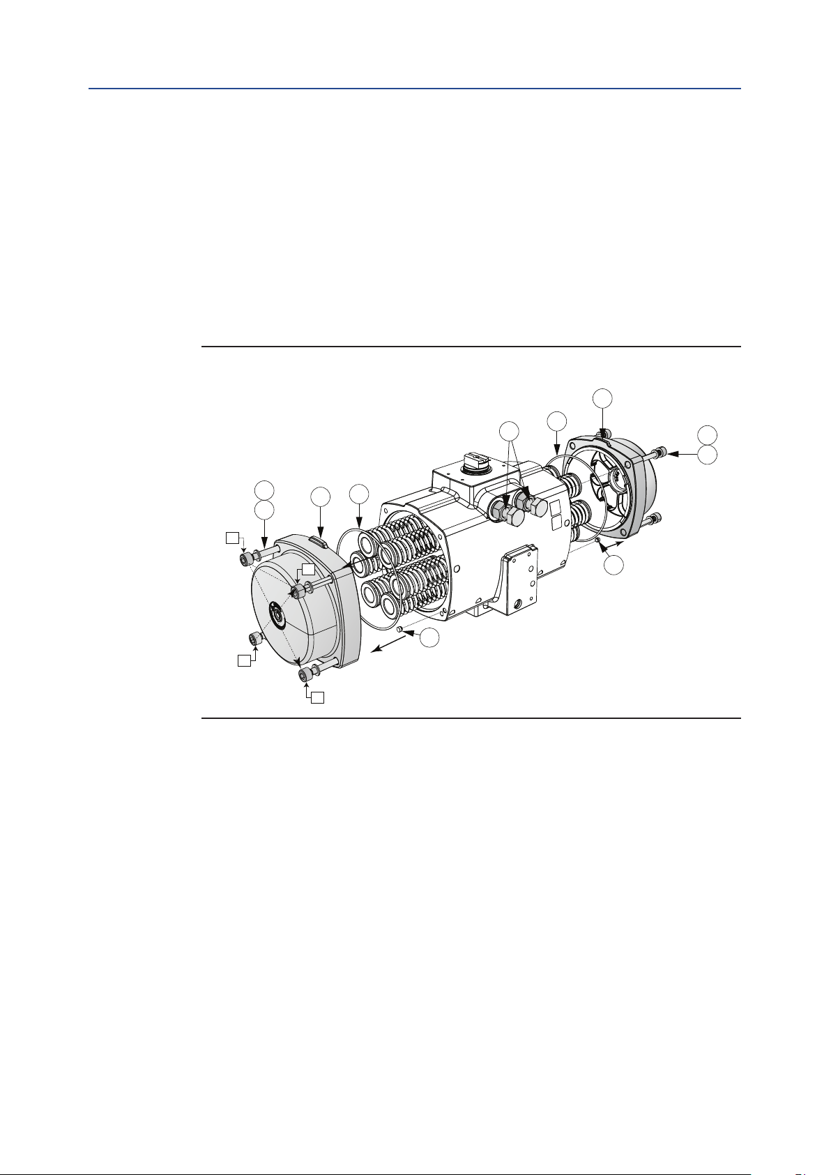
2. For Spring-return actuators, do the following:
a. Tip: For actuators with assembly code CW, turn back the right hand limit
stop screw (30) 2 full turns.
For actuators with assembly code CC, turn back the left hand limit stop
screw (30) 2 full turns.
This will lower the spring force on the end cap and reduces the screw out
length of the end cap screws.
b. Uniformly loosen the screws (9) of the end caps (5) 1/4-1/2 turns at a
time, in sequence, as per Figure 23, to relieve the pre-load of the springs.
c. Remove the o-rings (11) and "B" port seals (2). Discard these parts.
Figure 23 Spring-Return End Caps Removal
30
Section 8: Disassembly
April 2019
5
11
10
9
10
9
3
2
1
11
5
2
2
4
Disassembly
35
Page 40
Section 8: Disassembly
April 2019
Installation, Operation and Maintenance Manual
8.2 Removing End Caps (Size 950 to 1600)
1. For Double-acting actuators, do the following:
a. Remove the screws (8) and washers (10) of the end caps (6).
b. Remove the o-ring (11) and "B" port seal (2). Discard these parts.
Figure 24 Double-Acting End Caps Removal Size 950 to 1600
11
DOC.IOM.Q.E Rev. D
10
8
6
11
2
2. For Spring-return actuators, do the following:
a. Tip: For actuators with assembly code CW, turn back the right hand limit
stop screw (30) 2 full turns.
For actuators with assembly code CC, turn back the left hand limit stop
screw (30) 2 full turns.
This will lower the spring force on the end cap and reduces the screw out
length of the end cap screws.
b. Uniformly loosen the screws (9) of the end caps (5) 1/4-1/2 turns at a
time, in sequence, as per Figure 25, to relieve the pre-load of the springs.
c. Remove the o-rings (11) and "B" port seals (2). Discard these parts.
6
8
10
2
36
Figure 25 Spring-Return End Caps Removal Size 950 to 1600
10
9
3
6
1
5
2
4
11
5
2
11
30
5
10
9
2
Disassembly
Page 41

Installation, Operation and Maintenance Manual
DOC.IOM.Q.E Rev. D
Section 8: Disassembly
8.3 Removing Spring Cartridges or Springs
1. Remove the spring cartridges or springs (7).
Figure 26 Removing Spring Cartridges Size 40 to 600
7
April 2019
7
Figure 27 Removing Springs Size 950 to 1600
7
7
Disassembly
37
Page 42

Section 8: Disassembly
April 2019
Installation, Operation and Maintenance Manual
8.4 Removing of Limit Stop Screws
1. Remove the limit stop screws (30), limit stop nuts (31), limit stop washers (32) and
limit stop o-rings (33). Discard the o-rings.
Figure 28 Limit Stop Removal
32
33
31
DOC.IOM.Q.E Rev. D
30
8.5 Removing Pistons
1. Use a wrench and turn the pinion counterclockwise until the pistons (14) come out
of the body.
2. Remove the piston bearings (15), piston rack bearing strips (17) and piston o-ring
seals (16). Discard these parts.
Figure 29 Removing Pistons
17
14
16
15
14
16
15
17
38
Disassembly
Page 43
Sizes 950 and 1600
Sizes 40 to 600
Installation, Operation and Maintenance Manual
DOC.IOM.Q.E Rev. D
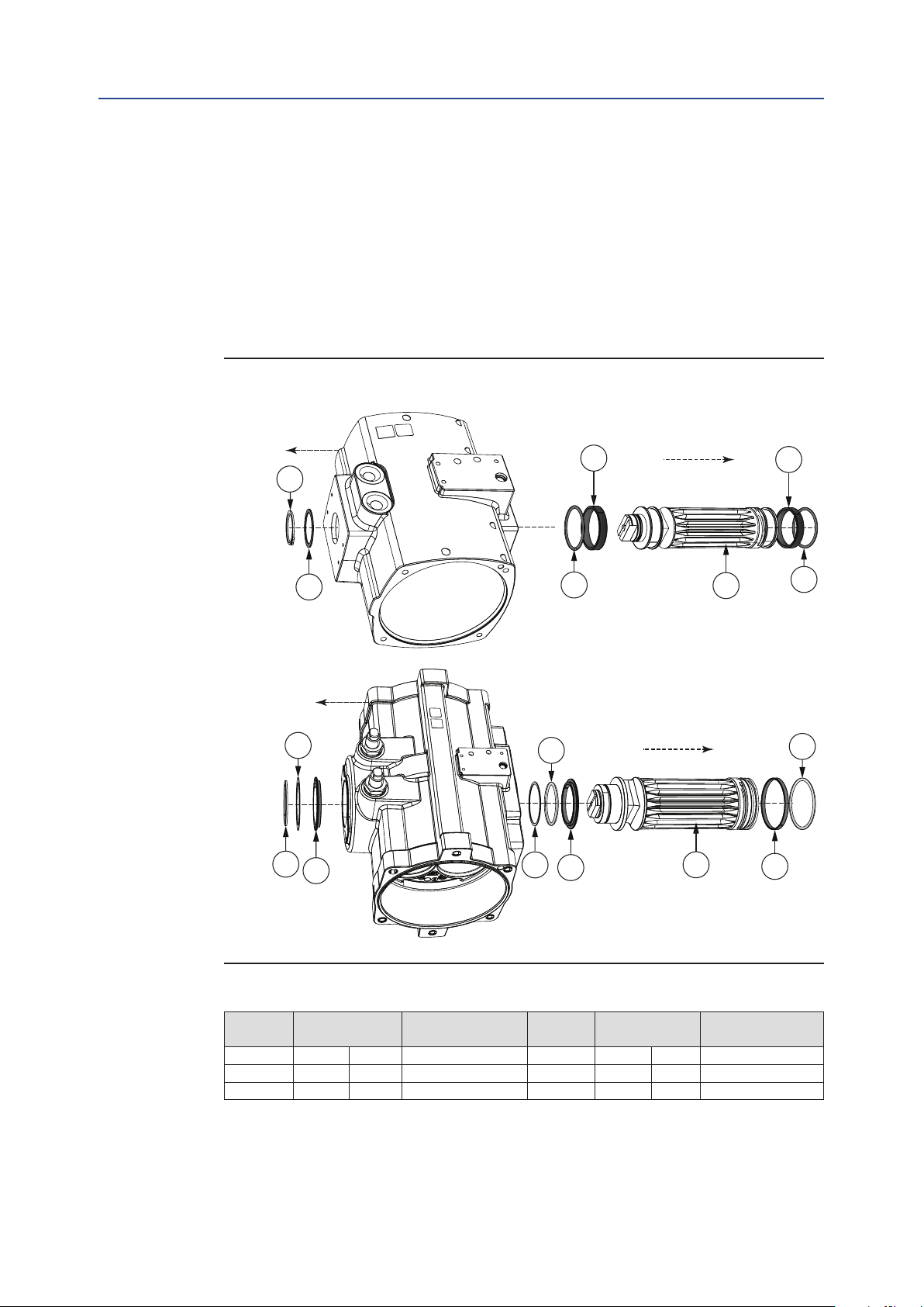
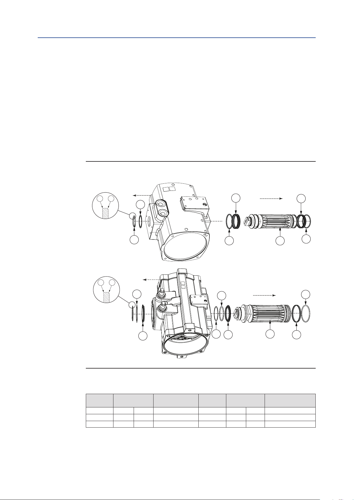
8.6 Removing Pinion
1. Remove the circlip (27) and thrust bearing (23) on top of the pinion assembly.
For sizes 950 to 1600 remove also the top pinion bearing (19).
2. Remove the pinion (18) by pushing it downwards.
3. Remove the pinion O-ring seals (21/22) and the pinion bearings (19/20).
For Size 950 to 1600, remove also the backup ring (29).
4. Discard all of these parts.
Figure 30 Pinion Removal
Section 8: Disassembly
April 2019
27
27
23
23
19
29
21
21
19
19
18
18
19
21
22
20
Disassembly
Table 13. Recommended circlip pliers according DIN 5254 (or equal) for shaft circlip
Actuator
size
40 - 100 22 mm 0.866" A2 950 65 mm 2.559" A3
150 - 350 36 mm 1.417" A3 1600 75 mm 2.953" A3
600 55 mm 2.165" A3
Pinion top
diameter
Pliers according
DIN 5254
Actuator
size
Pinion top
diameter
Pliers according
DIN 5254
39
Page 44

Section 9: Reassembly
April 2019
Installation, Operation and Maintenance Manual
8.7 Cleaning the Components
In case of maintenance, use a clean dry cloth and thoroughly wipe clean and remove old
grease from:
• The inside and outside of the body including thread holes and crevices/grooves.
• The pinion gears.
• The pistons.
DOC.IOM.Q.E Rev. D
40
Reassembly
Page 45

Installation, Operation and Maintenance Manual
DOC.IOM.Q.E Rev. D
Section 9: Reassembly
This section explains:
• Which parts and how to grease them.
• How to reassemble a complete actuator.
• How to set the stroke adjustment bolts after reassembly.
• How to do a basic function and air leak test.
Tip
The instructions of this section can be used for maintenance or reconguration like spring
set change or maintenance.
Reference numbers for components refer to the exploded view in Section 11.
In case of maintenance, discard all used soft parts like O-ring seals, guide bands and wear
strips and circlip and replace them with the parts as supplied in the repair kit.
Section 9: Reassembly
April 2019
In case of reconguration replace the parts as supplied in the conversion kit
(see also Section 6).
Refer to the Safety Guide for Lifting Instructions.
NOTICE
The actuator is designed to be installed, commissioned and maintained using generic tools
like wrenches, Allen keys and screwdrivers.
Refer to the tables in this section or refer to Appendix B Tool and Torque tables.
Reassembly
41
Page 46
Section 9: Reassembly
Installation, Operation and Maintenance Manual
April 2019
9.1 Grease Instructions
Check the product coding on the product labels and Section 3 of this manual, to dene
which type of grease to use.
Table 14. Recommended greases
Standard temperature: High temperature: Low Temperature:
-20°C to +80°C /
-4°F to +176°F
- Castrol High Temperature - Formerly called Castrol LMX
- Rocol Sapphire Premier - Formerly called Sapphire HI-TEMP 2
- Castrol Spheerol EPL 2 - Formerly called BP Energrease LS-EP2
- Total Ceran XM 220 - Formerly called Total Ceran WR2
We recommend using a suitable sized paint brush to apply the required amount of grease
on the parts as per Table 15 and Figure 31.
Table 15. Grease Instruction
-10°C to +120°C /
+14°F to +250°F
DOC.IOM.Q.E Rev. D
-40°C to +80°C /
-40°F to +176°F
- Castrol Optitemp LG2
- SKF – LGLT 2
- FUCHS – Renolit Unitemp 2
Part Section of part Amount of grease
O-rings: A Completely Light lm
B Piston bore Light lm
Housing Parts:
C Top pinion bore Light lm
D Bottom pinion bore Light lm
E O-ring & bearing groove Light lm
Piston Parts:
F Rack teeth Half the teeth depth full with grease
G Piston bearing Light lm on outside
H Piston rack bearing strip Light lm
J Pinion bottom & O-ring groove Light lm
K Pinion top & O-ring groove Light lm
Piston Parts:
L Gear teeth Half the teeth depth
M Pinion top bearing Light lm (inside and out)
N Pinion bottom bearing Light lm (inside and out)
Figure 31 Grease Instructions
A
E
F
A
C
H
E
A
G
A
H
G
42
B
F
M
A
K
J
D
A
L
N
A
Reassembly
Page 47
Installation, Operation and Maintenance Manual
DOC.IOM.Q.E Rev. D
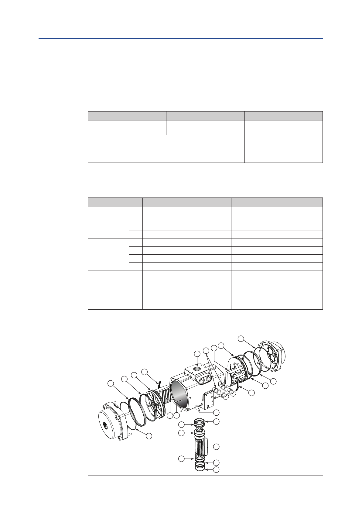
9.2 Reassembly of the Pinion
1. Grease the pinion parts according to Section 9.1.
2. Install the pinion bearings (19/20) and the O-ring seals (21/22) on the pinion (18).
For Size 950 to 1600, install also the the backup ring (29).
3. Insert the pinion (18) in the housing.
4. For sizes 950 to 1600 install rst the top pinion bearing (19). For all sizes, install
the thrust washer (23) and mount the circlip (27) on the pinion top.
— Install the new circlip onto its mating groove on the top shaft extension
and with the non-sharp edge (2) towards the housing and the sharp edge
(1) towards the top of the shaft.
Figure 32 Reassemble the Pinion
Sizes 40 to 600
1
2
23
Section 9: Reassembly
19
April 2019
19
21
22
20
Sizes 950 and 1600
1
2
27
23
19
29
21
21
19
18
18
Table 16. Recommended circlip pliers according DIN 5254 (or equal) for shaft circlips
Actuator
size
40 - 100 22 mm 0.866" A2 950 65 mm 2.559" A3
150 - 350 36 mm 1.417" A3 1600 75 mm 2.953" A3
600 55 mm 2.165" A3
Pinion top
diameter
Pliers according
DIN 5254
Actuator
size
Pinion top
diameter
Pliers according
DIN 5254
Reassembly
43
Page 48

Section 9: Reassembly
April 2019
Installation, Operation and Maintenance Manual
9.3 Reassembly of the Pistons
NOTICE
Before reassembling the pistons, check the required assembly code (see Section 4.4).
1. Grease the piston parts according to step 9.1.
2. Install the piston rack bearing strips (17) and piston O-ring seals (16) on the
pistons (14). Ensure all these parts are kept in place during assembly.
Figure 33 Reassemble the Pistons
17
16
14
14
DOC.IOM.Q.E Rev. D
16
17
15
3. Before aligning the pinion and pistons, verify the actuator size and the location
of the limit stop screws (D), see Figure 34. Align the pinion so that the teeth on
the pinion will pick up the pistons rack teeth when turning the pinion. Note the
position of the pinion top slot and the cam on the pinion top:
— For standard or Spring-to-Close: Assembly Code CW.
— For reverse or Spring-to-Open: Assembly Code CC.
4. Slightly push the pinion inward to engage with the pinion.
— Ensure that smooth movement and 90-degree operation can occur with-
out moving the pistons out of the actuator body.
— For larger pistons, use a rubber mallet and slightly hitting the pistons
inward to engage with the pinion.
5. When the pistons are moved 90° inwards (see Figure 34), check that the pinion
slot on the pinion top is:
— Perpendicular to the length centre line of the house for assembly code CW.
— In line to the length centre line of the house for assembly code CC.
6. If not, turn pinion to move the pistons outward until they disengage from the
pinion. Shift one tooth of the pinion, reassemble and check again.
7. Move the pistons outward so that just the bearing groove sticks out of the
housing. Fold the piston bearings (15) around the piston and hold the bearing
ends in place while moving the pistons inwards.
— For larger pistons, use a rubber mallet and slightly hitting the pistons
inward to engage with the pinion.
15
44
Reassembly
Page 49
Installation, Operation and Maintenance Manual
DOC.IOM.Q.E Rev. D
Figure 34 Position of the Slot and the Cam on the Pinion Top
Assembly code CW Assembly code CC
(Standard; Spring-to-Close) (Reverse; Spring-to-Open)
Section 9: Reassembly
April 2019
Sizes Q40 to Q100
Sizes Q150 to Q1600
A
DD
A
B
90°
C
B
B
A
90°
C
B
A
Reassembly
D
90°
C
D
90°
C
A = Position of cam C = Final position of pinion dot
B = Position of slot and dot in pinion D = Position of limit stop screws
NOTE:
When the pistons are completely moved inwards, the pinion top will show a 5° over travel.
45
Page 50
30
31
32
33
Section 9: Reassembly
April 2019
Installation, Operation and Maintenance Manual
DOC.IOM.Q.E Rev. D
9.4 Reassembly and Settings of the Limit Stops
1. Install the limit stop screws (30), limit stop nuts (31), limit stop washers (32) and
limit stop O-rings (33).
Figure 35 Install Limit Stop Bolts
2. Move the pistons inward until the slot in the top of the pinion is pendicular to
centerline of the housing.
3. Double check if the position of the slot and the cam on the pinion top is in the
correct position (see Figure 34). Screw in the right hand travel stop until it comes
into contact with the pinion stop face.
4. Move the pistons outward until the slot in the top of the pinion is in line with the
centerline of the housing.
5. Screw in the left hand travel stop until it comes into contact with the pinion
stop face.
— For accurate travel stop adjustment of the actuator on the valve,
see Section 5.
46
Reassembly
Page 51
Installation, Operation and Maintenance Manual
DOC.IOM.Q.E Rev. D
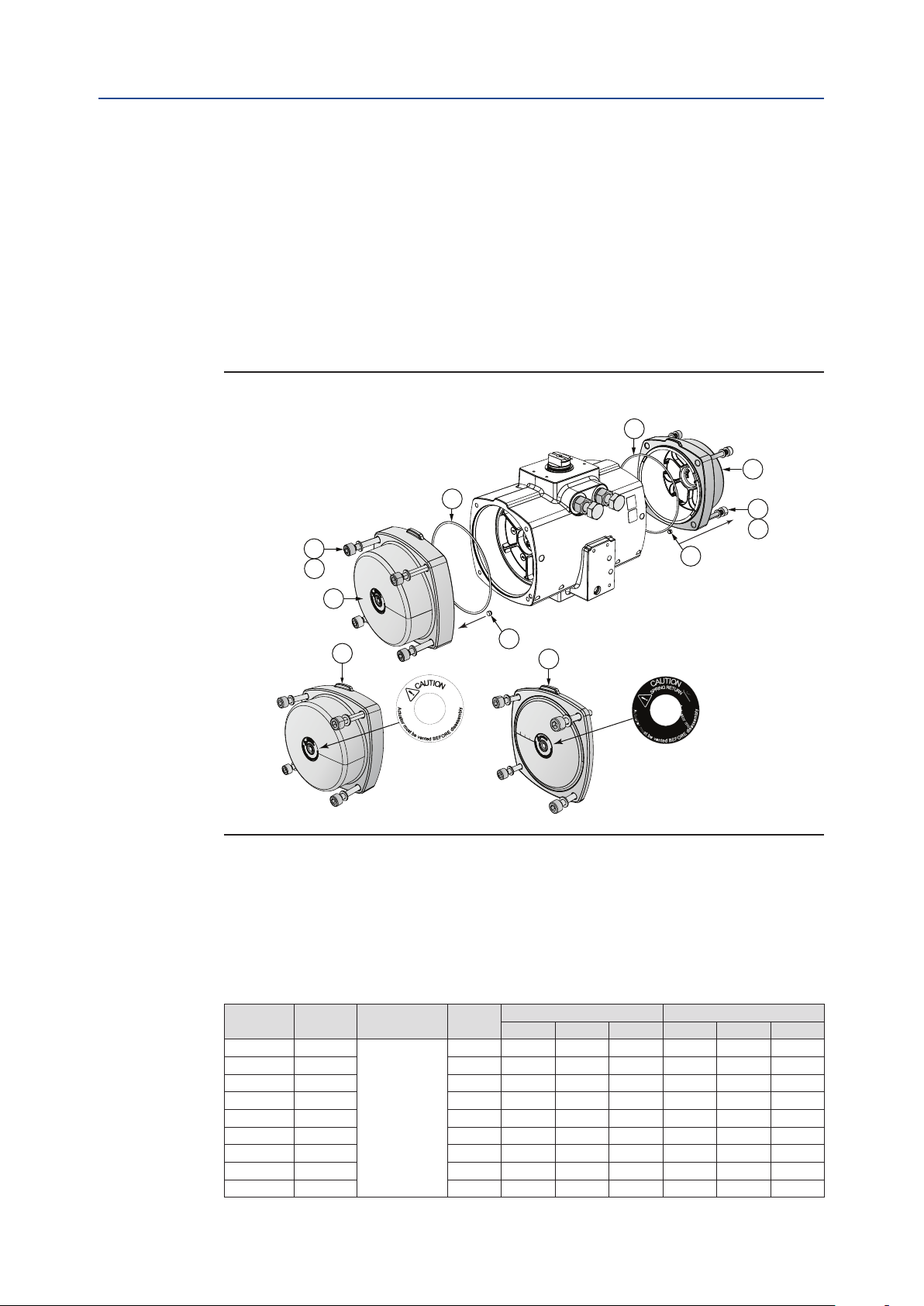
9.5 Reassembly of the End Caps
9.5.1 Double-Acting Actuators
1. Grease the O-ring seals (11) and B port seals (2) according to step 9.1.
2. Ensure that O-ring seals (11) and B port seals (2) are kept in place during assembly.
3. Install the end caps (6) and tighten the end cap screws (8).
Refer to Table 17 for the correct torque.
Figure 36 Double-Acting End Cap Assembly
Section 9: Reassembly
April 2019
11
6
8
10
11
2
6
6
2
5
8
10
Double acting end caps (6) are fitted with a white warning sticker. Spring return end
caps (5) are fitted with a black warning sticker.
Actuator sizes 40 to 100 have high end caps for double-acting and spring-return models.
Actuator sizes 150 to 1600 have low end caps for double-acting models and high end
caps for spring return models.
Reassembly
Table 17. End Cap Screw Torque
Actuator
size
Q 40 M5
Q 65 M5 SW 4 2.0 1.6 3.0 1.5 1.2 2.2
Q 100 M5 SW 4 2.0 1.6 3.0 1.5 1.2 2.2
Q 150 M6 SW 5 3.3 2.6 5.1 2.4 1.9 3.8
Q 200 M6 SW 5 3.3 2.6 5.1 2.4 1.9 3.8
Q 350 M8 SW 6 8.4 6.7 12.2 6.2 4.9 9.0
Q 600 M10 SW 8 15.3 12.2 24.8 11.3 9.0 18.3
Q 950 M12 SW10 24.3 19.4 41.6 17.9 14.3 30.7
Q 1600 M12 SW10 24.3 19.4 41.6 17.9 14.3 30.7
Thread Tool Size
SW 4 2.0 1.6 3.0 1.5 1.2 2.2
Allen Key
Torque (Nm) Torque (lbf.ft)
Target Min. Max. Target Min. Max.
47
Page 52

1
2 3
4
56
A
B
1
2
3
4
56
1
23
4
56
N = 10 N = 20
N = 30
1
2 3456
1
23
4
5
6
1
23
4
5
6
N = 40
N = 50
N = 60
A = Piston top view
B = Position of piston gear rack
Section 9: Reassembly
Installation, Operation and Maintenance Manual
April 2019
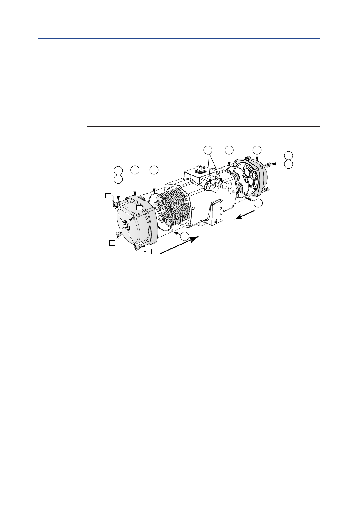
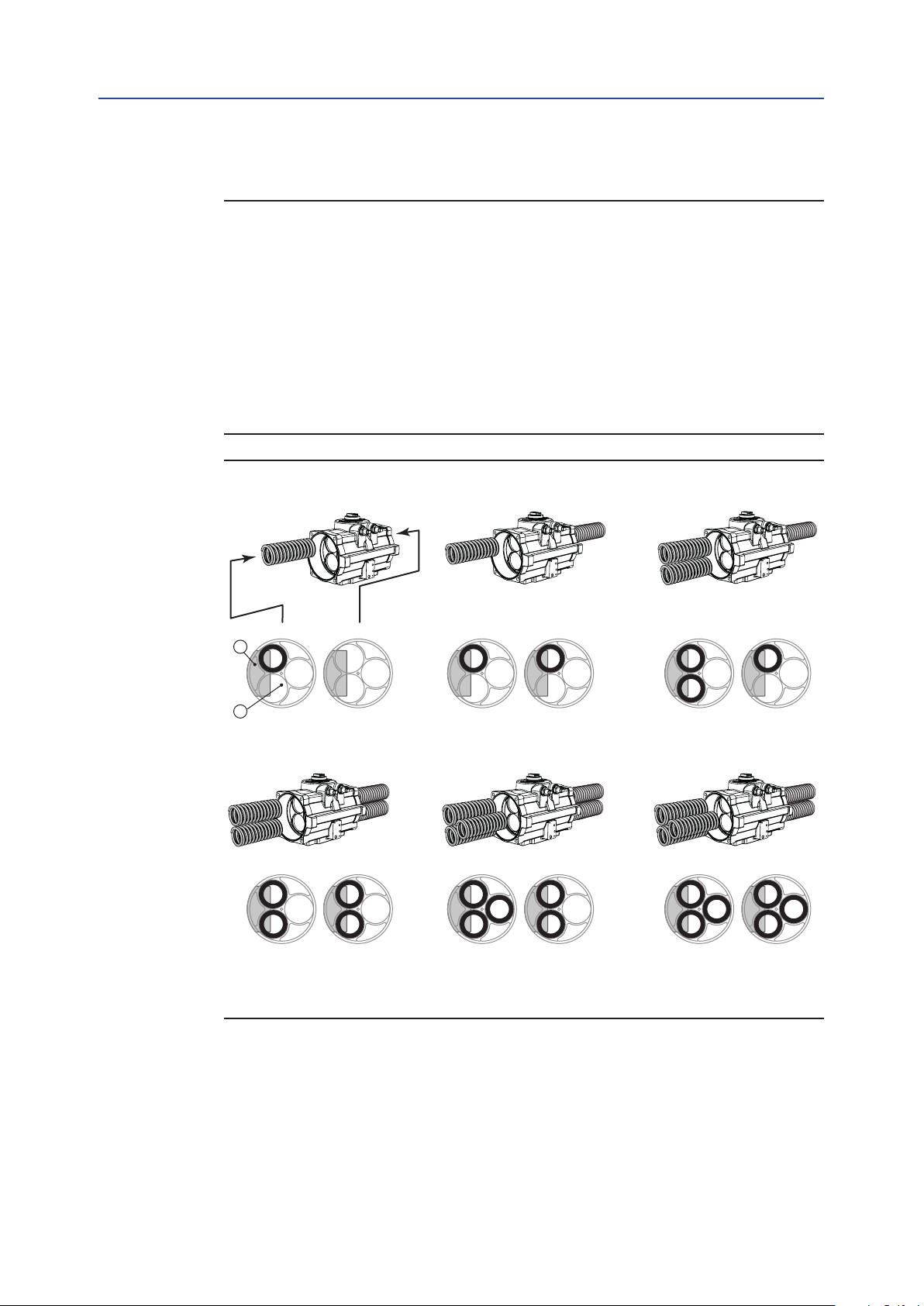
9.5.2 Spring-Return Actuators (Size 40 to 600)
Important
FieldQ Spring return actuators are supplied with springs on each side of the actuator.
Throughout the Q-Series size range, there are three different spring designs:
— Sizes Q40 to Q600 have 6 springs on each side (see Figure 37).
— Sizes Q950 to Q1600 have 3 springs on each side (see Section 9.5.3).
Check below gures to see where to place the spring cartridges in case of spring set conversion.
When replacing spring cartridges in a spring-return actuator, ensure that the cartridges are
replaced in their identical position from where they were removed.
Before assembling the spring cartridges and end caps, make sure that the pistons are
completely inwards.
Figure 37 Spring Placement Size 40 to 600
DOC.IOM.Q.E Rev. D
48
Reassembly
Page 53
Installation, Operation and Maintenance Manual
DOC.IOM.Q.E Rev. D
1. Grease the O-ring seals (11) and B port seals (2) according to step 9.1.
2. Ensure that O-ring seals (11) and B port seals (2) are kept in place during assembly.
3. Place the spring cartridges in actuator as per required spring set (see Figure 37).
4. Put the end cap screw washer (10) on the end cap screw (9) and tighten each end
cap screw in small equal turns and in the sequence as per Figure 38. Refer to Table
17 for the correct torque. We recommend to use some grease on the screws for
easier fastening.
Figure 38 Spring-Return End Cap Assembly Size 40 to 600
Section 9: Reassembly
April 2019
30
5
10
9
3
1
11
2
2
4
11
5
10
9
2
Reassembly
49
Page 54
N = 10 N = 20 N = 30
A = Piston top view
B = Position of piston gear rack
Section 9: Reassembly
April 2019
Installation, Operation and Maintenance Manual
9.5.3 Spring-Return Actuators (Size 950 to 1600)
Important
FieldQ Spring return actuators are supplied with springs on each side of the actuator.
Throughout the Q-Series size range, there are three different spring designs:
— Sizes 40 to 600 have 6 springs on each side (Section 9.5.2).
— Sizes 950 to 1600 have 3 springs on each side (see Figure 39).
Check below gures to see where to place the springs in case of spring set conversion.
When replacing springs in a spring-return actuator, ensure that the springs are replaced in
their identical position from where they were removed.
Before assembling the springs and end caps, make sure that the pistons are completely inwards.
Figure 39 Spring Placement Size 950 and 1600
DOC.IOM.Q.E Rev. D
Left RightLeftRight Left Right
B
A
1 spring 0 spring 1 spring 1 spring 2 springs1 spring
N = 40 N = 50 N = 60
Left
2 springs
Right Left RightLeftRight
2 springs 3 springs2 springs3 springs3 springs
50
Reassembly
Page 55

Installation, Operation and Maintenance Manual
DOC.IOM.Q.E Rev. D
1. Grease the O-ring seals (11) and B port seals (2) according to step 9.1.
2. Ensure that O-ring seals (11) and B port seals (2) are kept in place during assembly.
3. Place the spring in actuator as per required spring set (see Figure 39).
4. Put the end cap screw washer (10) on the end cap screw (9) and tighten each end
cap screw in small equal turns and in the sequence as per Figure 40.
Refer to Table 17 for the correct torque. We recommend to use some grease on
the screws for easier fastening.
Figure 40 Spring-Return End Cap Assembly Size 950 to 1600
Section 9: Reassembly
April 2019
10
9
3
6
1
5
2
4
11
5
2
11
30
2
5
10
9
Reassembly
51
Page 56
Section 9: Reassembly
April 2019
Installation, Operation and Maintenance Manual
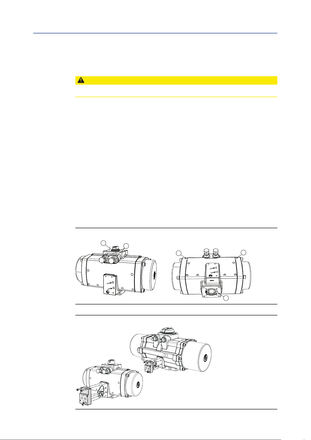
9.6 Basic Function and Air Leak Test
CAUTION: MOVING PARTS
Applying pressure to the actuator will cause the actuator/valve assembly to operate.
1. Apply pressure (max. 8 bar/120 psi) to ports A and B. Use some soap suds at the
indicated points: around pinion top (1), pinion bottom (2), the end caps (3) and
limit stops (4).
2. In case of leakage around:
a. The limit stop bolts: Turn the lock nut of the bolts tighter,
until the leakage stops.
b. The end caps: Disassemble the end caps, replace o-rings and reassemble.
c. The pinion top or bottom and A- or B- port: Disassemble the complete
actuator, replace o-rings and reassemble.
3. When needed mount now the NAMUR adaptation plate. Apply pressure to the
NAMUR plate's A and B port.
4. Use some soap suds around the NAMUR plate to check for leakage.
In case of leakage:
a. Tighten the NAMUR plate's screws.
b. If this does not solve the leakage replace the NAMUR plate's seals.
DOC.IOM.Q.E Rev. D
Figure 41 Basic Function and Air Leak Test
1
A
B
4
3
Figure 42 NAMUR Plate Mounting
3
A
B
2
52
Reassembly
Page 57

Installation, Operation and Maintenance Manual
DOC.IOM.Q.E Rev. D
Section 10: Troubleshooting
10.1 Mechanical Problems
Problem Possible error Solution Where to find
Feedback position and
actual position are not
the same.
Valve is in “Closed”
position, actuator is in
“Open” position and will
not move anymore.
Actuator and valve are
mounted 90° rotated in
relation to each other.
Limit stop screws are not
set correctly.
Remove actuator from
valve. Check assembly code
of actuator. Put both valve
and actuator in “Closed”
position. Mount actuator on
valve.
Readjust the limit stop
screws.
Section 10: Troubleshooting
April 2019
Section 4
Section 5
Valve does not reach the
completely “Closed” or
“Open” position.
Actuator rotates, valve
does not.
Actuator does not
rotate or does not rotate
smoothly.
Limit stop screws cannot
be turned out anymore.
Insert is not mounted
properly.
Pressure to low. Apply pressure as per sizing.
Sizing is wrong.
Pinion is mounted in the
wrong position.
No coupling between
actuator shaft and valve
spindle.
Broken gearing on
pistons or pinion.
Spring or Spring
cartridge is broken.
Limit stop screws is
bend.
Mount the insert in the right
position. Remark: Rotate
insert to one cam = 22.5°.
Check valve torque data
with actuator torque data.
Re assemble actuator. Section 9
Install a coupling between
actuator shaft and valve
spindle.
Contact nearest FieldQ
representative to replace
actuator.
Contact nearest FieldQ
representative to replace
actuator.
Contact nearest FieldQ
representative to replace
actuator.
Section 4.5
Section 4.5
Appendix A.
Troubleshooting
53
Page 58

Section 10: Troubleshooting
April 2019
Installation, Operation and Maintenance Manual
10.2 Pneumatic Problems
Problem Possible error Solution Where to find
Actuator does not react
to electrical control
signal.
Actuator does not
react good to electrical
control signal.
Air leakage between
actuator and solenoid
valve.
There is no supply
pressure at the
actuator.
There is sufcient
supply air pressure but
insufcient supply air
capacity.
Supply pressure too
low, causing pilot
operated solenoid valve
to fail.
Solenoid valve is not
mounted properly.
Speed control throttle
(if present) blocks air
ow.
Manual override
(if present) on the
Solenoid Valve is
locked.
Sealing between
solenoid valve and
actuator is not
mounted air tight.
Supply the right
pressure to the
actuator.
Take care the supply
air tubing has the right
dimensions.
Check that supply
pressure at the
actuator and solenoid
is sufcient to operate
the actuator.
Check the solenoid
valve mounting.
Turn the speed control
more open.
Unlock manual override
on the solenoid valve.
Reassemble solenoid
valve taking care, that
all seals are in place.
DOC.IOM.Q.E Rev. D
Section 2.3
Check that the actual
supply pressure is
higher than the sizing
pressure.
Section 4.6
Section 2.3
Check that the actual
supply pressure is
higher than the sizing
pressure.
Instructions shipped
with the solenoid valve.
Instructions shipped
with the speed control
valve.
Instructions shipped
with the manual
override.
Instructions shipped
with the solenoid valve.
Double-acting actuator
will only move to
“open” position.
Leakage notice on the
actuator.
Actuator has wrong
solenoid valve
conguration.
Seals on the limit stops
screws are not air tight.
Seals on the end caps
are not air tight.
Seals on the pinion top
and bottom are not air
tight.
Mount a solenoid valve
suitable for double-
acting actuators
(4/2 or 5/2 function).
Check that conversion
plate on solenoids, that
have both 3/2 and 5/2
functions, is in the right
position.
Turn the lock nut of the
bolts tighter; until the
leakage stops.
Disassemble the end
caps, replace O-rings
and reassemble.
Consider to replace
all O-ring seals and
bearings.
Disassemble the
complete actuator,
replace O-rings and
reassemble. Consider
to replace all O-ring
seals and bearings.
Instructions shipped
with the solenoid valve.
Instructions shipped
with the solenoid valve.
Section 9.6
Section 9.6 or Section 6
Section 9.6 or Section 6
54
Troubleshooting
Page 59

Installation, Operation and Maintenance Manual
DOC.IOM.Q.E Rev. D
10.3 Electrical Problems
Problem Possible error Solution Where to find
Control wiring. Power
supply wiring or
feedback wiring are not
Actuator does not react
to control signals.
There are problems
with position feedback
after sending the
actuator to either the
“Open” or “Closed”
position.
right connected.
The power supply
voltage is not is not the
same as the voltage of
the applicable solenoid
valve.
The wiring of the
feedback signals may
be switched.
Section 10: Troubleshooting
Connect all wiring in
the right way.
Connect the right
power supply voltage.
Connect the feedback
wiring in the right way.
April 2019
Instructions of the
control or feedback
accessories.
Instructions of the
solenoid valve.
Instructions of the
feedback device.
Troubleshooting
55
Page 60
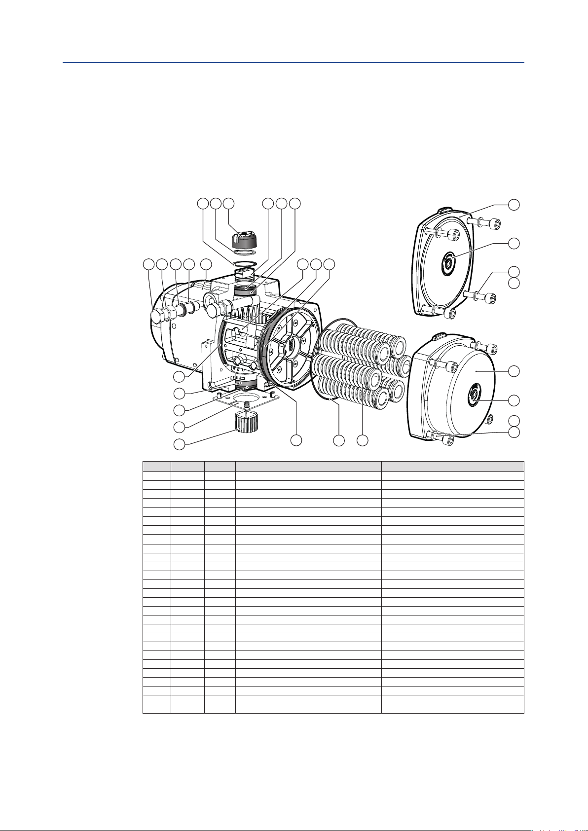
Section 11: Parts List and Spare Parts
April 2019
Installation, Operation and Maintenance Manual
DOC.IOM.Q.E Rev. D
Section 11: Parts List and Spare Parts
Recommendations
11.1 Actuator Size Q40 to Q600
29
30
31
17
19
21
28
23
27
26
32
1
3
19
2118
16
15
14
2
11
7
Pos. Qty Notes Description Material
1 1 House Cast Aluminium alloy
2 2 1 B-port seal Nitrile rubber
3 1 Center plate (option) Nylon PA6, Black
5 2 2 End cap SR (DA) Cast Aluminium alloy
6 2 2 End cap DA Cast Aluminium alloy
7 Max. 12 Spring cartridge Spring steel
8 8 End cap screw DA Stainless Steel
9 8 End cap screw SR Stainless Steel
10 8 End cap screw washer Stainless Steel
11 2 1 O-ring end cap Nitrile rubber
12 2 Warning sticker DA Polyester
13 2 Warning sticker SR Polyester
14 2 Piston Cast Aluminium alloy
15 2 1 Bearing piston PTFE 25% carbon-lled
16 2 1 O-ring piston Nitrile rubber
17 2 1 Bearing strip piston rack POM
18 2 Pinion High grade aluminium
19 2 1 Bearing pinion POM
21 2 1 O-ring pinion Nitrile rubber
23 1 1 Thrust bearing pinion POM, black UV stabilized
26 1 Indicator assembly ABS + stainless steel screw
27 1 1 Circlip Spring steel
28 1 Drive insert Aluminium
30 2 Limit stop screw Stainless steel
31 2 Limit stop nut Stainless steel
32 2 1 Limit stop washer PA66
33 2 1 O-ring limit stop Nitrile rubber
Notes:
1 Included in Service Kit.
2 Actuator sizes 40 to 100 have high end caps for double-acting and spring-return models. Actuator sizes
150 to 1600 have low end caps for double-acting models and high end caps for spring-return models.
6
12
8
10
5
13
9
10
56
Parts List and Spare Parts
Page 61

Installation, Operation and Maintenance Manual
Section 11: Parts List and Spare Parts
DOC.IOM.Q.E Rev. D
11.2 Actuator Size Q950 to Q1600
19
26
23
29
18
27
21
15
1
33
32
31
30
April 2019
6
8
12
9
10
5
13
3
28
4
11 72
Pos. Qty. Description Material
1 1 House Cast Aluminium alloy
2 2 1 B-port seal Nitrile rubber
3 1 Center plate (option) Nylon PA6, Black
4 12 Thread insert Steel
5 2 End cap SR Cast Aluminium alloy
6 2 End cap DA Cast Aluminium alloy
7 Max. 6 Springs Spring steel
8 12 End cap screw DA Stainless Steel
9 12 End cap screw SR Stainless Steel
10 12 End cap screw washer Stainless Steel
11 2 1 O-ring end cap Nitrile rubber
12 2 Warning sticker DA Polyester
13 2 Warning sticker SR Polyester
14 2 Piston Cast Aluminium alloy
15 2 1 Bearing piston PTFE 25% carbon-lled
16 2 1 O-ring piston Nitrile rubber
17 2 1 Bearing strip piston rack POM
18 1 Pinion High grade aluminium
19 2 1 Bearing pinion top POM
20 1 1 Bearing pinion bottom POM
21 1 1 O-ring pinion top Nitrile rubber
22 1 1 O-ring pinion bottom Nitrile rubber
23 1 1 Thrust bearing pinion POM, black UV stabilized
26 1 Indicator assembly ABS + stainless steel screw
27 1 1 Circlip Spring steel
28 1 Drive insert Aluminium
29 1 1 Backup ring POM
30 2 Limit stop screw Stainless steel
31 2 Limit stop nut Stainless steel
32 2 1 Limit stop washer PA66
33 2 1 O-ring limit stop Nitrile rubber
Notes:
1 Included in Service Kit.
Parts List and Spare Parts
57
Page 62

Appendix
April 2019
Installation, Operation and Maintenance Manual
Appendix A: Spring Load Removal
This section explains:
• How to remove the spring load safely of spring-return actuators in case:
— The valve gets “stuck” in mid position.
— One of the spring cartridges is broken.
WARNING: MOVING PARTS
A spring-return actuator mounted on a valve, which is stuck in mid stroke, contains a high
spring load which will cause a sudden rotation of the actuator versus the valve during
disassembly. This can cause serious injury to personnel or damage to material.
On spring-return actuators with a broken spring cartridge, the end cap can be “shot” away
during disassembly of the actuator. This can cause serious injury to personnel or damage
to material.
DOC.IOM.Q.E Rev. D
A.1 Spring Load Relief
CAUTION: ROTATING ACTUATOR
In case of an actuator/valve assembly “stuck” in mid position, leave the actuator on the
valve and/or mounting bracket during this procedure.
Figure A-1 Spring Load Removal
3
2
1
4
WARNING
Crush / Amputaion Hazard
Failure to follow instructions
for removal of spring loaded
actuator may result in
surious personal injury
58
Appendix
Page 63
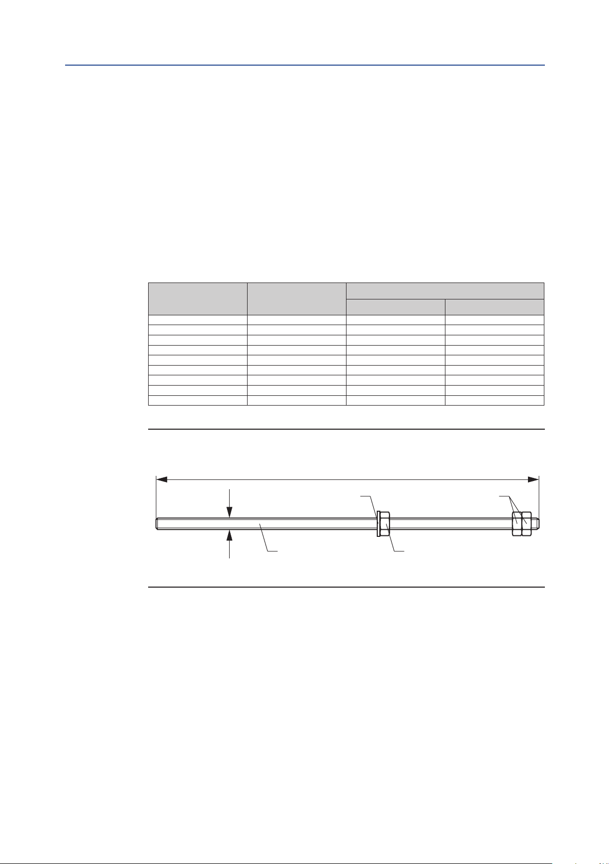
Installation, Operation and Maintenance Manual
DOC.IOM.Q.E Rev. D
1. Depressurize the actuator completely.
2. Based on the actuator size, choose the correct threaded rod kit from Table A-1.
3. Replace one by one each end cap screw for the threaded rod kit and turn down the
adjusting nut until it touches the end cap.
4. Once all for end cap screws have been replaced, gradually turn the adjustment nuts
on threaded rod in CCW direction by turning the nuts half turn at a time. Make sure
the rod itself does not turn. Continue this until the load of springs are relieved.
5. Repeat the same procedure for the end cap screws on the other size of the
actuator as shown in Figure A-1.
6. In case of an actuator/valve assembly “stuck” in mid position: The actuator now
can be disassembled from Valve, by removing the mounting studs/bolts.
Table A-1. Threaded Rod Dimensions in mm
Appendix
April 2019
Actuator Size Thread
Q 40 M5 140 5.5
Q 65 M5 140 5.5
Q 100 M5 140 5.5
Q 150 M6 145 5.7
Q 200 M6 145 5.7
Q 350 M8 185 7.3
Q 600 M10 185 7.3
Q 950 M12 498 19.6
Q 1600 M12 498 19.6
Figure A-2 Spring Load Removal Rod Dimensions
Length
Thread
Washer
Threaded Rod
Threaded rod length
(mm) (inch)
Holding nuts
Adjusting nut
Appendix
59
Page 64

Appendix
Installation, Operation and Maintenance Manual
April 2019
Appendix B: Tool & Torque Table
This section explains:
• Which tools to use for the indicated fasteners.
• The recommended amount of torque to apply on the indicated fasteners.
Table B-1. End Cap Bolts
Actuator
size
Q 40 M5
Q 65 M5 SW 4 2.0 1.6 3.0 1.5 1.2 2.2
Q 100 M5 SW 4 2.0 1.6 3.0 1.5 1.2 2.2
Q 150 M6 SW 5 3.3 2.6 5.1 2.4 1.9 3.8
Q 200 M6 SW 5 3.3 2.6 5.1 2.4 1.9 3.8
Q 350 M8 SW 6 8.4 6.7 12.2 6.2 4.9 9.0
Q 600 M10 SW 8 15.3 12.2 24.8 11.3 9.0 18.3
Q 950 M12 SW10 24.3 19.4 41.6 17.9 14.3 30.7
Q 1600 M12 SW10 24.3 19.4 41.6 17.9 14.3 30.7
Thread Tool Size
SW 4 2.0 1.6 3.0 1.5 1.2 2.2
Allen Key
Torque (Nm) Torque (lbf.ft)
Target Min. Max. Target Min. Max.
DOC.IOM.Q.E Rev. D
Table B-2. Bottom Flange, Metric Units
Actuator
size
40, 65, 100
150, 200, 350
600
950
1600
ISO Pattern
F05 inner pattern M6 4.5 5.0 1/4"-20 3.3 3.7
F07 outer pattern M8 10.5 12.5 5/16"-18 7.7 9.2
F07 inner pattern M8 10.5 12.5 5/16"-18 7.7 9.2
F10 outer pattern M10 21.0 24.5 3/8"-16 15.5 18.1
F10 inner pattern M10 21.0 24.5 3/8"-16 15.5 18.1
F12 outer pattern M12 34.5 43.0 1/2"-13 25.4 31.7
F10 inner pattern M10 21.0 24.5 3/8"-16 15.5 18.1
F14 outer pattern M16 90.0 104.0 5/8"-11 66.4 76.7
F16 inner pattern M20 170.0 204.0 3/4"-10 125.4 150.5
F25* outer pattern 4x M16 90.0 104.0 4x 5/8"-11 66.4 76.7
1. Actuator size 1600 has only 4 holes of the ISO5211 F25 drilling pattern are available.
Metric Torque (Nm) Imperial Torque (lbf.ft)
Thread Min. Max. Thread Min. Max.
Table B-3. Adaptation Plate
Flange
Solenoid ange screw threads M5 2.0 3.0 10-24UNC 1.5 2.2
Top ange screw threads M5 2.0 3.0 10-24UNC 1.5 2.2
Metric Torque (Nm) Imperial Torque (lbf.ft)
Thread Min. Max. Thread Min. Max.
Table B-4. Limit Stop Screws
Actuator size Thread
40 M 8 13 13
65 M 10 17 (16)
100 M 10 17 (16)
150 M 10 17 (16)
200 M 12 19 (18)
350 M 16 24 24
600 M 20 30 30
950 M 22 12 32
1600 M 24 14 36
1. Default dimension according DIN933 standard
2. Dimensions in brackets according ISO4017 standard
Bolt Wrench Nut wrench
size (mm) size (mm)
1
1
1
1
17 (16)
17 (16)
17 (16)
19 (18)
1
1
1
1
60
Appendix
Page 65

Installation, Operation and Maintenance Manual
DOC.IOM.Q.E Rev. D
Table B-5. Recommended circlip pliers according DIN 5254 (or equal)
for shaft circlips
Actuator size Pinion top diameter
Q40 - Q100 22 mm 0.866" A2
Q150 - Q350 36 mm 1.417" A3
Q600 55 mm 2.165" A3
Q 950 65 mm 2.559" A3
Q 1600 75 mm 2.953" A3
Table B-6. Angular Displacement Limit Stops
Actuator size
Q 40 0.8 6.3°
Q 65 0.6 8.3°
Q 100 0.7 7.1°
Q 150 1.2 4.2°
Q 200 1 5.0°
Q 350 0.8 6.3°
Q 600 0.8 6.3°
Q 950 1.1 4.7°
Q 1600 1.3 4.1°
adjustment of the pinion:
Turns for 5°
Appendix
April 2019
Pliers
according DIN
360° revolution of
limit stop screw will adjust
Appendix
61
Page 66
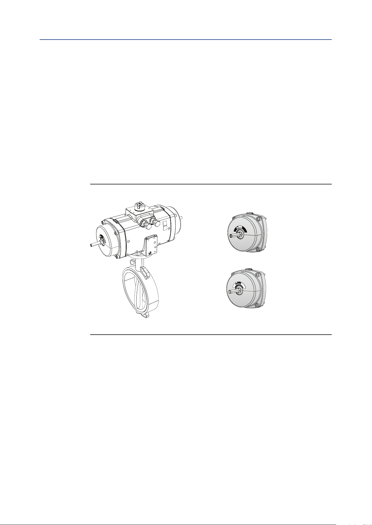
Appendix
April 2019
Installation, Operation and Maintenance Manual
DOC.IOM.Q.E Rev. D
Appendix C: Full Stroke Adjustment Option
This section explains:
• How to mount the Full Stroke Adjustment option to an actuator.
• How to adjust the Full Stroke Adjustment option to a required rotation angle.
C.1 Full Stroke Adjustment Option
The Full Stroke Adjustment option is available as a complete actuator or as an end cap
conversion kit in order to upgrade a standard actuator into a Full Stroke Ajdustment version.
The option is available for sizes 40 to 600 and both the double acting kit and spring return
kit use the spring return end cap.
Figure C-1 Availability Formats of the Full Stroke Adjustment Option
Complete Spring-Return
or Double-Acting actuator
Spring-Return Full
Stroke Adjustment Kit
Double-Acting Full
Stroke Adjustment Kit
62
Appendix
Page 67

Installation, Operation and Maintenance Manual
DOC.IOM.Q.E Rev. D
Appendix
April 2019
C.2 Convert a Standard Actuator into a Full Stroke
Adjustment Version
Before starting to assemble the Full Stroke adjustment kit, please check the kit for
completeness. See Figure C-2.
Figure C-2 Full Stroke Adjustment Kit Content
13
12
45
46
11
41
42
43
44
40 9 10
Table C-1 Content Full Stroke Adjustment kit
Pos. Description Material Qty. Notes
40 End cap - Full stroke adjustment Cast Aluminium alloy 2 1
41 Full Stroke adjustment screw Stainless steel 2
42 Full Stroke adjustment Nut Stainless steel 2
43 Full Stroke adjustment washer PA66 2
44 O-Ring - Full Stroke adjustment screw Nitrile rubber 2
45 O-Ring - Thread bush Nitrile rubber 2
46 Thread bush Aluminium 2
9 End cap screw Stainless steel 8
10 Washer end cap screw Stainless steel 8
11 O-ring end cap Nitrile rubber 2
12 Warning sticker DA Full Stroke adjustment Polyester 2
13 Warning sticker SR Full Stroke adjustment Polyester 2
1. The same Full Stroke adjustment end cap is used for both double acting and spring return actuators
(at double acting actuator end caps with Full Stroke Adjustoment options are not available).
Appendix
63
Page 68
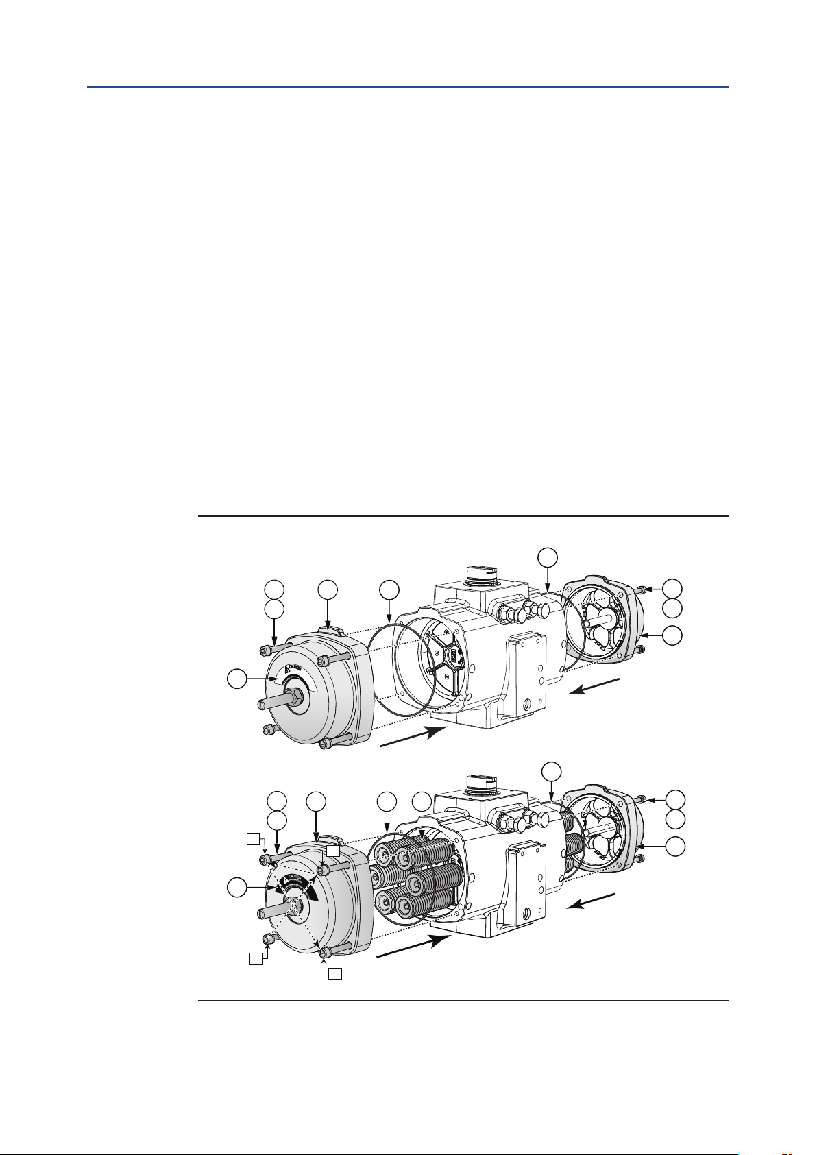
Appendix
April 2019
C.2.1 Procedure
1. Remove the existing end caps of a standard actuator.
— Follow the instructions of Section 8 to remove both the end caps of
— For spring return actuators; note the original positions of the
2. Mount the Full Stroke Adjustment End cap kit to the actuator.
— The stroke adjustment screw (41) is factory set at the 90° position.
3. Grease the O-ring seals (11) and B port seals (2) according to Section 9.1.
4. Ensure that O-ring seals (11) and B port seals (2) are kept in place during assembly.
5. For spring return actuators; place the spring cartridges (7) back in their original
positions.
6. Install the Full Stroke end cap kits and tighten the end cap screws (9,10). For spring
return units; tighten each endap screw (9,10) in small equal turns and in the se-
quence as per Figure C-3. Refer to Appendix B, Table B-1 for the correct torque.
7. For Spring Return units, place the black warning sticker (13) on the end cap.
For Double Acting units, place the white warning sticker (12) on the end cap.
Installation, Operation and Maintenance Manual
DOC.IOM.Q.E Rev. D
the actuator.
spring cartridges.
Figure C-3 Assembly of Full Stroke Adjustment End Cap Kit
11
12
13
9
10
9
10
3
40
40
2
11
11
11
7
9
10
40
9
10
40
64
1
4
Appendix
Page 69
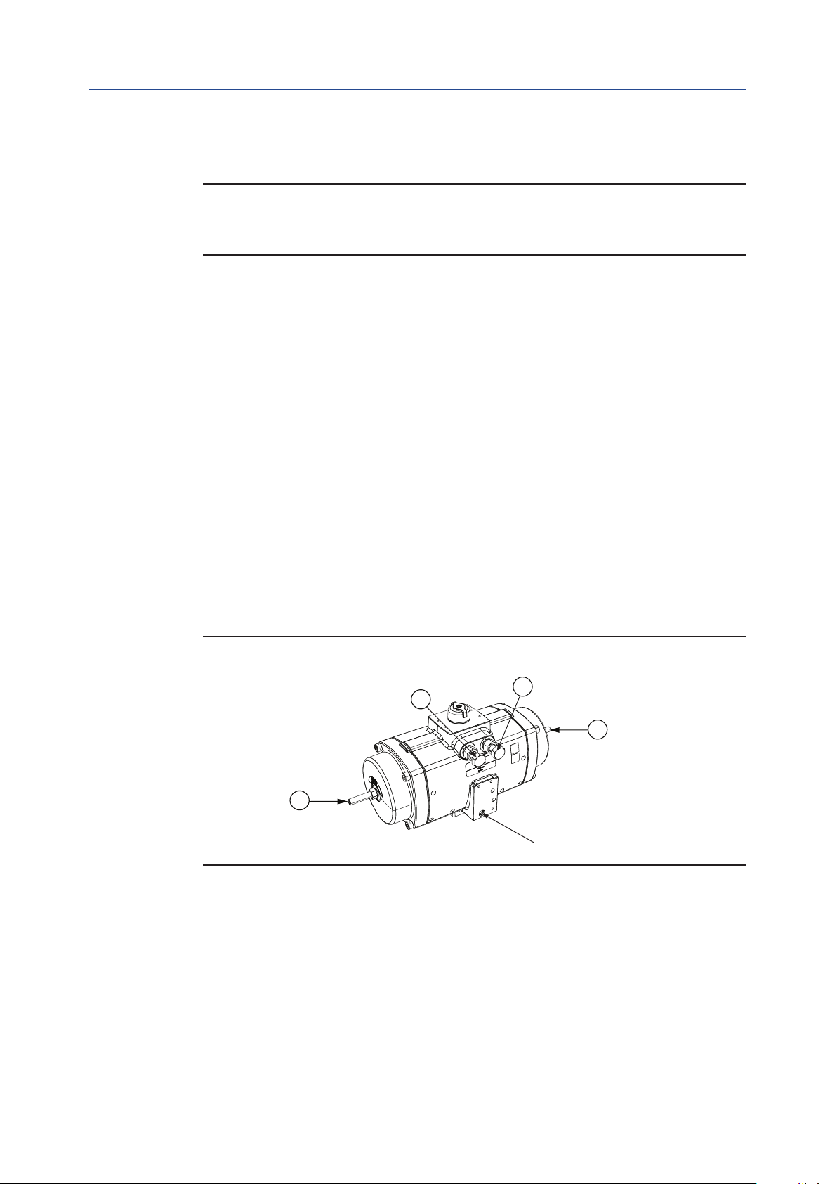
Installation, Operation and Maintenance Manual
DOC.IOM.Q.E Rev. D
C.3 Full Stroke Adjustment Setting
NOTE:
Standard actuators or actuators with the Full Stroke Adjustment option are shipped by
default with a rotation setting of 90° +/-0.5°.
The stroke adjustment setting procedure can be two steps:
1. Setting the Full Stroke Adjustment screw to the 90° (factory) poisiton.
— This step can be applicable if a standard actuator needs to be converted
with a Full Stroke Adjustment end cap kit or if the position of the Full
Stroke Adjustment screw is somehow lost.
2. Setting the Full Stroke Adjustment screw to the required angle.
C.3.1 Factory Setting Procedure
Appendix
April 2019
1. In order to set the Full Stroke Adjustment Screws accurately to the outward position:
— Do not change the setting of the DSA limit stop screws (A and B) located
above the air connection interface.
— Move the pistons of the actuator outwards by applying pressure to the
A-port.
2. Screw in both the Full Stroke Adjustment Screws (41) until the screws touch the
pistons. You will feel an obstruction.
Important: Do not overtighten the screws.
Figure C-4 DSA Limit Stop Screw Setting
A
41
B
41
A-port
Appendix
You have now set the adjustment screw to the factory setting
Notes:
1. Only the outward stroke can be adjusted with the Full Stroke Adjustment screws.
— In case of assembly code CW, the left side limit stop (A) is redundant.
— In case of assembly code CC, the right side limit stop (B) is redundant.
2. For the inward stroke the standard limit stops can be used:
— The right side limit stop (B) for assembly code CW
— The left side limit stop (A) for assembly code CC
65
Page 70
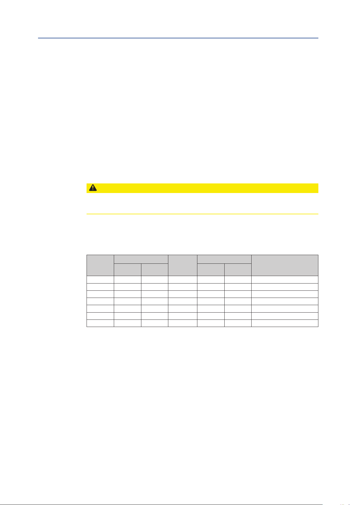
Appendix
April 2019
Installation, Operation and Maintenance Manual
DOC.IOM.Q.E Rev. D
C.3.2 Setting the Full Stroke Adjustment Screw to the
Required Angle
1. Move the pistons of the actuator inwards.
— For Spring Return actuators this happens automatically when the actuator
is vented.
— For double acting actuators vent the A-port and apply pressure to the
B-port.
2. In order to set the actuator to the required angle, use next table to dene the
number of revolutions which you have to turn in the Full Stroke
Adjustment Screws.
3. Turn in both the adjustment screws (41) as dened in step 2. Both the adjustment
screws should be turned in with the same length or number of revolutions.
CAUTION: DO NOT SET SCREWS UN-EQUAL
Screwing in only one adjustment screw or un-equal setting of both the screws will lead to
high point loads on the pistons and can cause premature failure of the actuator.
4. Test cycle the actuator to check if the correct rotation angle is set. If required,
repeat steps 1 to 3 to adjust the rotation angle to the required angle.
Table C-2 Actuator angle rotation per full revolution of Full Stroke adjustment screw
Actuator
size
40 18.8 0.74 1.2 x 6.5 M8 1.25 6.0°
65 22.0 0.87 1.2 x 6.5 M8 1.25 5.1°
100 25.1 0.99 1.2 x 6.5 M10 1.5 5.4°
150 31.4 1.24 1.2 x 6.5 M10 1.5 4.3°
200 37.7 1.48 1.2 x 6.5 M10 1.5 3.6°
350 37.7 1.48 1.2 x 6.5 M12 1.75 4.2°
600 44.0 1.73 1.2 x 6.5 M16 2 4.1°
Stroke
mm inch Thread Pitch (mm)
Flathead
screw driver
Screw
Actuator angle rotation per
full revolution of screw
66
Appendix
Page 71

Page 72

World Area Confi guration Centers (WACC) offer sales support, service,
inventory and commissioning to our global customers.
Choose the WACC or sales offi ce nearest you:
NORTH & SOUTH AMERICA
19200 Northwest Freeway
Houston TX 77065
USA
T +1 281 477 4100
Av. Hollingsworth
325 Iporanga Sorocaba
SP 18087-105
Brazil
T +55 15 3413 8888
ASIA PACIFIC
No. 9 Gul Road
#01-02 Singapore 629361
T +65 6777 8211
No. 1 Lai Yuan Road
Wuqing Development Area
Tianjin 301700
P. R. China
T +86 22 8212 3300
For complete list of sales and manufacturing sites, please visit
www.emerson.com/actuationtechnologieslocations or contact us at
info.actuationtechnologies@emerson.com
MIDDLE EAST & AFRICA
P. O. Box 17033
Jebel Ali Free Zone
Dubai
T +971 4 811 8100
P. O. Box 10305
Jubail 31961
Saudi Arabia
T +966 3 340 8650
24 Angus Crescent
Longmeadow Business Estate East
P.O. Box 6908 Greenstone
1616 Modderfontein Extension 5
South Africa
T +27 11 451 3700
EUROPE
Holland Fasor 6
Székesfehérvár 8000
Hungary
T +36 22 53 09 50
Strada Biffi 165
29017 Fiorenzuola d’Arda (PC)
Italy
T +39 0523 944 411
www.emerson.com/fi eldq
©2019 Emerson. All rights reserved.
The Emerson logo is a trademark and service mark of Emerson Electric Co.
TM
is a mark of one of the Emerson family of companies.
FieldQ
All other marks are property of their respective owners.
The contents of this publication are presented for information purposes
only, and while every effort has been made to ensure their accuracy,
they are not to be construed as warranties or guarantees, express or
implied, regarding the products or services described herein or their use
or applicability. All sales are governed by our terms and conditions, which
are available on request. We reserve the right to modify or improve the
designs or specifications of our products at any time without notice.
FieldQ
Loading...