

Page 1
Installation, Operation and Maintenance Manual
GVO-LP-SR/FS Spring Return
E-90090003 Rev. A
May 2014
Page 2

Page 3

Installation, Operation and Maintenance Manual
E-90090003 Rev. A
Table of Contents
Section 1: Safety Warning
Section 2: Introduction
2.1 General Service Information .......................................................................... 2
2.2 Denition of Terms ........................................................................................ 2
2.3 Scope ............................................................................................................ 3
2.4 Model Identication ...................................................................................... 3
Section 3: Storage Instructions
Section 4: Operation
4.1 SR Operator ................................................................................................... 6
4.2 FS Operator ................................................................................................... 6
Table of Contents
May 2014
Section 5: Preparation
Section 6: Installation
6.1 Notes .......................................................................................................... 11
6.2 Lifting .......................................................................................................... 12
6.3 Procedures of Installation ............................................................................ 13
Section 7: Maintenance
7.1 Regular Maintenance ................................................................................... 17
7.2 Disassembly ................................................................................................ 17
7.3 Inspection and Cleaning .............................................................................. 22
7.4 Reassembly ................................................................................................. 22
Section 8: Operator End Stop Adjustment
8.1 SR - End Stop Adjustment Conditions .......................................................... 27
8.2 FS - End Stop Adjustment Conditions ........................................................... 28
Section 9: Testing and Troubleshooting
9.1 Testing ........................................................................................................ 31
9.2 Troubleshooting .......................................................................................... 31
Section 10: Document Revision ����������������������������������������� 34
Appendix A: List of Tables ���������������������������������������������������35
Appendix B: List of Figures ��������������������������������������������������36
ITable of Contents
Page 4

Section 1: Safety Warning
May 2014
Installation, Operation and Maintenance Manual
Section 1: Safety Warning
All personnel involved should read and understand all applicable sections of this manual
before attempting to install, operate, service, or perform maintenance on any operators.
Adhere to any tags, warning labels, or instructions present on the operator.
These may provide information more specic and signicant regarding the operator than
this general manual can.
It is the responsibility of the user to ensure proper safety. Always take necessary
precautions and utilize proper personal protective equipment when dealing with
compressed air, compressed hydraulic uid, pinch points, and electricity.
It is necessary to rig and lift valve and operator separately. Service personnel need to
ensure the lifting capacity of the crane/hoist/rigging is appropriate for the desired load.
Block the pressure supply and depressurize the system before attempting to install or
service. Isolate the pressure from controls if the operator is supplied with control system.
Caustic gases and uids may be contained in the operators and valves in most applications.
Vent all poisonous or ammable gases and store all liquids in a safe location to prevent
personnel injury. Discharge at sonic velocity may occur when venting or releasing pressure;
service personnel must utilize proper hearing protection.
E-90090003 Rev. A
CAUTION: DO NOT DISASSEMBLE SPRING CARTRIDGE
Springs are under compression. Do not disassemble any part of the spring cartridge.
The following are general instructions since there are variations of linear operators
and valves. It is critical to install the operator properly so that performance and safety
are guaranteed. Any technicians using the following instructions must be trained and
knowledgeable regarding valve operators and valves.
CAUTION: DISASSEMBLE OPERATOR CAREFULLY
Go through the above instructions to help prevent personnel injury, property damage, and
damage to operator.
Please refer to the applicable section for details and further information.
1
Safety Warning
Page 5

Installation, Operation and Maintenance Manual
E-90090003 Rev. A
Section 2: Introduction
2�1 General Service Information
This Installation, Operation, and Maintenance (IOM) manual is for Bettis™ GVO Series
Pneumatic Spring Return Valve Operator (type SR or FS). Failure to comply with installation,
operation, and maintenance instructions will void the warranty and may result in severe
injury and/or property damage.
2�2 Definition of Terms
The abbreviations included in this IOM manual are listed in the table below:
Table 1� Definition of Terms
Section 2: Introduction
May 2014
Abbreviated
Ter m
IOM Installation, Operation, and Maintenance
GVO Gate Valve Operator
LP Low Pressure Pneumatic
SR Spring Stroke - Drive Rod (or Piston Rod) in Extension
FS Spring Stroke - Drive Rod (or Piston Rod) in Retraction
TDM Tandem Power Cylinder
ID Inside Diameter [inch]
OD Outside Diameter [inch]
BCD Bolt Circle Diameter
MVT Maximum Valve Stem Travel
MOT Maximum Operator Travel
MAWP Maximum Allowable Working Pressure
Definition
WARNING
If not observed, user incurs a high risk of severe damage to operator and/or fatal injury
to personnel.
CAUTION
If not observed, user may incur damage to operator and/or injury to personnel.
Introduction
NOTE:
Advisory and information comments provided to assist maintenance personnel to carry out
maintenance procedures.
2
Page 6

Section 2: Introduction
May 2014
2�3 Scope
This manual is a resource for technicians involved in the installation, operation, and
maintenance of Bettis™ Gate Valve Operator (GVO) Series Pneumatic Linear Valve
Operators. It serves as a guide and must be thoroughly understood prior to any work on
the operators such as installation, operation, or maintenance. For any questions, please
contact the manufacturer.
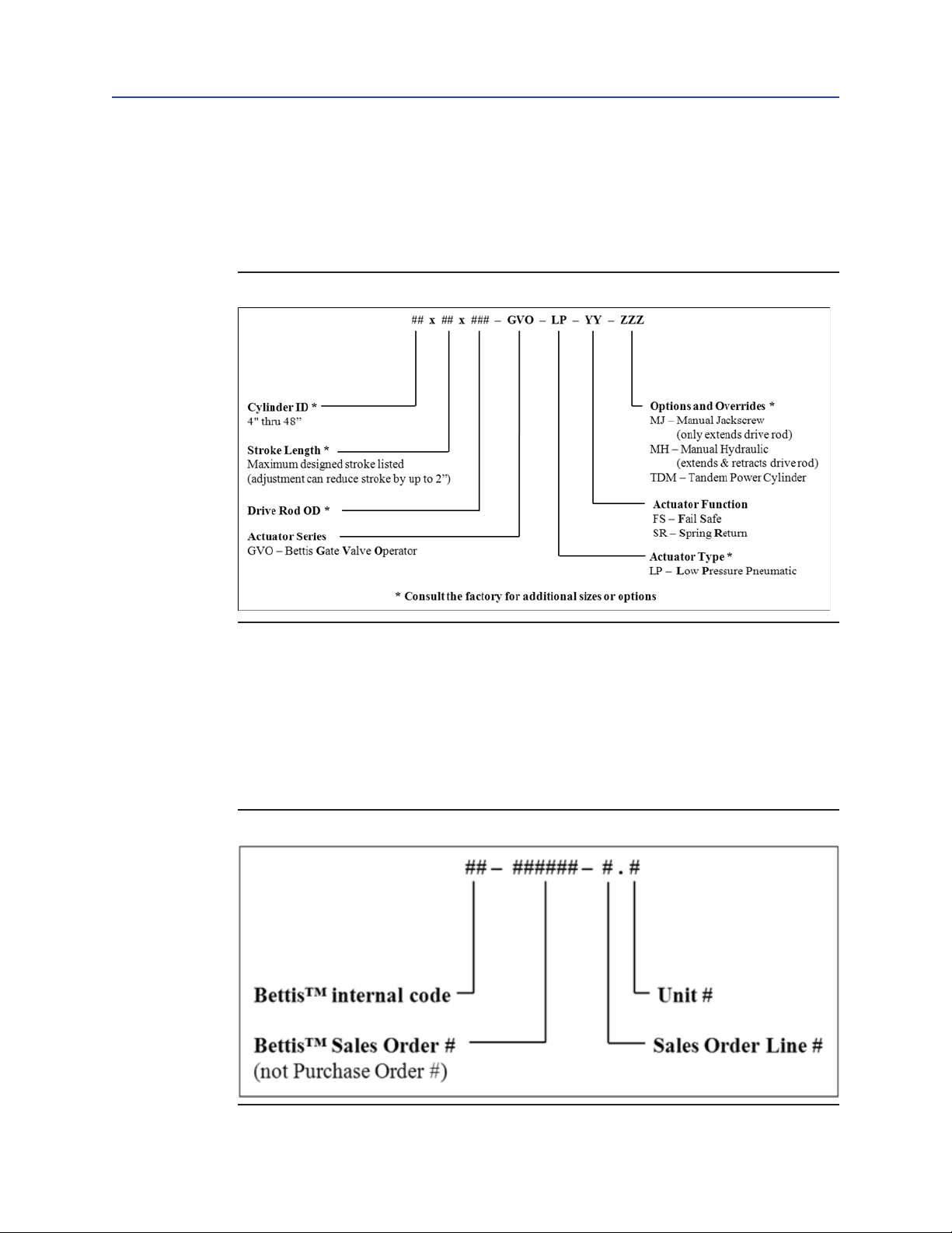
2�4 Model Identification
The Bettis GVO Pneumatic Series represents a broad range of eld-proven linear valve
operators suitable for automating most types of rising stem valves in safety shutdown
and control applications. Figure 1.
assembly drawing of Bettis™ GVO-LP-FS operator.
(Typical Assembly of GVO-LP-FS )
Installation, Operation and Maintenance Manual
E-90090003 Rev. A
shows the typical
Figure 1 Typical Assembly of GVO-LP-FS
3
Introduction
Page 7
Installation, Operation and Maintenance Manual
E-90090003 Rev. A
The catalog lists standard models intended to cover a wide range of sizes and applications.
Customers can use Figure 2.
(Linear Valve Operator Model Designation)
operator characteristics. If not included in the catalog lists, custom designed models are
also available for specialized thrust or stroke requirements or those beyond the scope of
this listing (including linear hydraulic operated operators).
Figure 2 Linear Valve Operator Model Designation
Section 2: Introduction
May 2014
to identify the key
To illustrate, a model number of 16x10x2.50-GVO-LP-SR-MH is an operator with a 16 [inch]
inside diameter cylinder, a 10 [inch] maximum stroke (adjustable down to 8 [inch] stroke),
a 2.50 [inch] outside diameter drive rod, and is low-pressure pneumatic spring return with
a manual hydraulic override.
Operators will also be identied with an individual serial number.
Figure 3.
(Linear Valve Operator Serial Number)
shows the form of the BettisTM serial number.
Figure 3 Linear Valve Operator Serial Number
Introduction
For example, a serial number of 00-123456-2.1 represents the rst unit on the second line
of sales order 123456.
4
Page 8

Sections 3: Storage Instructions
May 2014
Installation, Operation and Maintenance Manual
Section 3: Storage Instructions
Proper storage is required when the operator will not be used immediately.
1. Remove all dirt, dust, grease, and contaminants from the exposed drive rod (1)
surface by using a soft cloth dampened with an appropriate oil-based solvent.
Avoid using abrasive material when cleaning rod surfaces.
2. Exposed drive rod (1) must be protected to avoid damage to the surface.
a. FS style operator: Drive rod is retracted into the cylinder (only a portion
of the rod is exposed). Lightly grease the exposed surface and wrap with
protective material if necessary.
b. SR style operator: Drive rod is fully extended from the cylinder. User must
protect the rod surface to avoid damage (which in turn will compromise
and/or damage the sealing capability during operation). Lightly grease
and wrap the rod surface with protective material.
3. Remove the plastic plugs (used to plug the pressure ports during assembly) and
replaced with steel plugs. Any controls present should also be plugged with steel
plugs.
E-90090003 Rev. A
NOTE:
Sealants such as pipe dope or Teon tape should be applied to steel plug threads.
4. Lightly lubricate all exposed threads and unpainted surfaces
(for example, bottom of pedestal plate).
5. Cover the operator to prevent accumulation of dirt and debris.
6. Repeat the storage steps listed above to ensure the proper storage condition (in
case the operator will be moved and stored again).
Indoor environment is the ideal storage condition for the operator.
For additional information on storage, please contact the manufacturer.
5
Storage Instructions
Page 9

Installation, Operation and Maintenance Manual
E-90090003 Rev. A
Section 4: Operation
4�1 SR Operator
SR type operator contains spring which is located above the piston. Therefore, under spring
stroke, spring force will act on the piston to push the drive rod (1) into fully extended position.
To retract the drive rod (1), supply compressed air/Nitrogen to the piston (11) through the port
in the cylinder plate (4). Upon loss of supply pressure, the operator will fully extend the drive
rod (in other words, valve stem in retraction).
4�2 FS Operator
FS type operator contains spring which is located below the piston. Therefore, under spring
stroke, spring force will act on the piston to pull the drive rod (1) to fully retracted position.
To extend the drive rod (1), supply compressed air/Nitrogen to the piston (11) through the
port in the end cap (8). Upon loss of supply pressure, the operator will fully retract the drive rod
(in other words, valve stem in extension).
Sections 4: Operation
May 2014
Operation
6
Page 10

Section 5: Preparation
May 2014
Section 5: Preparation
Before working (installation, operation, or maintenance) on the operator, be sure to read
through all the applicable sections of the manual to ensure that you are familiar with the
expected sequence of events.
5�1 Tools
Listed are the recommended tools and materials that may be required when working on
the operator. Additional tools and materials may be required depending upon specic
operator and/or task.
• Vernier/measurement ruler
• A set of SAE combination wrenches and sockets
• A set of SAE hex keys
• Strap or pipe wrench (small to medium sizes)
• Large size ring wrench/hammer wrench
• Torque wrench with suitable rating
• Lifting device or a crane (complete with slings, a pair of shackles or clevises)
• Air supply or nitrogen not exceeding the MAWP of the operator
• Block and bleed test valve assembly for air supply/Nitrogen
• Anti-seize (lubricant) compound
• Pipe thread sealant (for example, Teon tape, pipe dope)
• Commercial solvent (for example, Varsol)
Installation, Operation and Maintenance Manual
E-90090003 Rev. A
5�2 Pre-Installation Verification
NOTE:
GVO linear operators shipped mounted to valves have their travel adjusted properly by the
manufacturer and do not require further adjustment. Install valve with GVO linear operator
directly in line. GVO linear operators shipped without a valve have their travel adjusted based
on the valve topworks (if available). Verify and ne-tune (if needed) the travel adjustment
when installing operator on the valve.
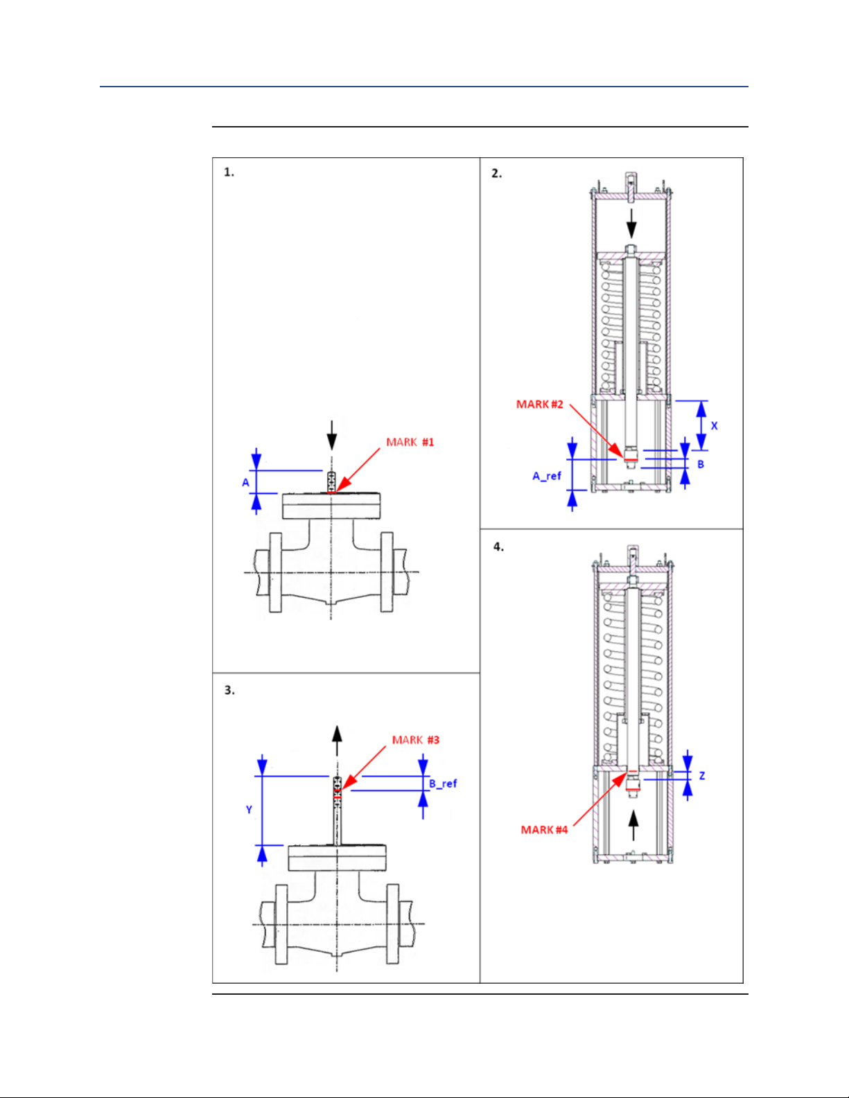
There are several critical measurements and markings to make before initial installation
of the operator on the valve. These measurements and markings are helpful for checking
or adjusting travel, however, it cannot be made after the operator is installed. Please refer
to Figure 4.
measurements.
NOTE:
Marks should be made with a marker, wax pen, or other tool that will not damage the sealing surfaces of the operator. Type FS style operator is used for illustration.
Follow the same instruction for SR style operator (with the exception of spring function).
7
(Measurement of Travel Adjustment for Valve and Operator)
when making
Preparation
Page 11
Installation, Operation and Maintenance Manual
E-90090003 Rev. A
Figure 4 Measurement of Travel Adjustment for Valve and Operator
Section 5: Preparation
May 2014
Preparation
8
Page 12

Section 5: Preparation
May 2014
1. Drive the valve stem fully into the valve body, ensuring that it is fully retracted
2. Actuate the operator (apply air to end cap side) to fully extend the drive
NOTE:
This will be spring stroke to fully extend the drive rod (if the operator is “SR” type).
Installation, Operation and Maintenance Manual
E-90090003 Rev. A
(consult valve manufacturer for procedure if required). If so equipped, remove valve
lever, handwheel, gear and/or jam nut/stop nut per valve-manufacturer instructions.
Strike the valve stem's threaded end using a soft mallet to retract valve stem fully.
Mark on the valve stem where it and the top of the valve ange align.
This is "MARK #1".
Measure from the top of the valve ange to the end of the valve stem using the
Vernier/measurement ruler. Record this value as "A".
A = ___________
rod (1). Mark on the swivel connector (80) the distance "A" up from the bottom of
the adapter plate. This is "MARK #2".
Measure from the mark to the bottom of the stem nut using the Vernier/measurement
ruler. Record this value as "B".
B = ___________
Also measure from the top of the body of the swivel connector (80) to the bottom of the
cylinder plate (4). Record this value as "X".
X = ___________
3. Pull the valve stem fully out of the valve body, ensuring that it is fully extended.
Mark on the valve stem a distance "B" down from the top of the valve stem.
This is "MARK #3".
Measure from the top of the valve ange to the top of the valve stem using the
Vernier/measurement ruler. Record this value as "Y".
Y = ___________
4. Actuate the operator (spring stroke) to fully retract the drive rod (1). Mark on the
drive rod (1) where it and the bottom of the cylinder plate (4) align (do not damage the drive rod's outside diameter sealing surface). This is "MARK #4".
NOTE:
This will be power stroke by applying air through cylinder plate port (if the operator is “SR” type).
9
Preparation
Page 13

Installation, Operation and Maintenance Manual
E-90090003 Rev. A
Measure from the top of the body of the swivel connector (80) to the bottom of the
cylinder plate (4) using the Vernier/measurement ruler. Record this value as "Z".
Z = ___________
To check: Perform the calculations below:
Y - A = Maximum Valve Stem Travel (MVT) = ___________
X - Z = Maximum Operator Travel (MOT) = ___________
If maximum operator travel (MOT) is less than or equal to maximum valve stem travel
(MVT), that means end stop (32) is factory set properly. Further verication is required
during the valve installation. If MOT is larger than MVT, refer to Section 8.
End Stop Adjustment)
for details on how to adjust the operator travel stop during valve
installation.
Section 5: Preparation
May 2014
(Operator
Preparation
10
Page 14

Section 6: Installation
May 2014
Section 6: Installation
6�1 Notes
CAUTION: BE CAREFULL ON PINCH POINTS
The areas inside the pedestal around the connector are pinch points for hands and ngers.
CAUTION: REMOVE LINE PRESSURE
Line pressure can cause a valve to open or close unexpectedly. It is recommended for the
installation to be performed on the valve with no pressure in the line.
Installation, Operation and Maintenance Manual
E-90090003 Rev. A
• GVO linear operators shipped mounted to valves have their travel adjusted
properly by the manufacturer and do not require further adjustment. Install valve
with GVO linear operator directly in line.
• If the valve is not shipped with the operator, the valve might need to be prepared
for installation. Any device that would restrict the free movement of the valve
stem or prevent installation of the operator (for example, handwheel or stem nut)
must be removed. Consult valve manufacturer for instructions.
• Be sure to use internally clean pipe or tubing when connecting to supply and
assure appropriate pressure and ow capacity for the operator. Clean dry-supply
gas will help ensure trouble-free operation.
• Check the valve and operator for compatibility before beginning installation.
Verify if the connector thread matches valve stem. Verify operator mounting
plate/valve gear ange connection (for example, bolt pattern, and alignment
bosses). Verify the proper amount, lengths, and sizes of mounting hardware
bolts, studs, lock washers, and others.
• Ensure threads and mating surfaces are free of dirt and debris.
11
Installation
Page 15

Installation, Operation and Maintenance Manual
E-90090003 Rev. A
6�2 Lifting
CAUTION: USE PROPER LIFTING EQUIPMENT
The operator's built-in lifting lugs/eyes are designed with the capacity to lift the BettisTM
GVO operator and the pedestal. Additional lifting support is required to lift the operator
with a valve attached. Always use an appropriately rated crane/hoist and appropriate
straps/chains when raising and lowering the operator.
Vertical Lifting:
Make sure that the valve is disconnected from the operator before lifting the operator.
Care must be taken when handling and installing the operator especially during rigging and
lifting. The operator should only be lifted from the lifting lugs located on the end cap as
shown in Figure 5.
NOTE:
Operators should be lifted with force acting as vertically as possible. Spreader bars or other
lifting aids may be required to maintain a vertical lift on the lugs or eyebolts. Always lift the
operator with a 60° or greater lifting angle measured from the horizontal plane.
(Lifting Method)
Section 6: Installation
.
May 2014
Figure 5 Lifting Method
Installation
12
Page 16

Section 6: Installation
May 2014
Installation, Operation and Maintenance Manual
6�3 Procedures of Installation
6.3.1 Operator Installation
1. For closed pedestal operators, removal of the window(s) from the operator
pedestal is required to provide access to the connector.
2. Complete the measurements in Section 5.2
in
the assembly of operator to valve and to ensure that the end stop is set properly.
3. Disconnect the tubing (if applicable) and connect the air supply/Nitrogen (a
block and bleed valve can be used to maintain pressure in the cylinder, locking
the drive rod in position). Do not exceed operator MAWP.
4. While extending the drive rod (1), a controlled stroking speed can be used to
travel the operator as you screw/rotate the stem nut section of the connector
onto the valve stem.
6.3.1.1 Operator Installation Conditions:
E-90090003 Rev. A
(Pre-installation Verication)
to aid
a. Condition A� Valve Stem Extended/Operator Drive Rod Retracted (typi-
cally FS style operator with drive rod retracted into cylinder)
b. Condition B� Valve Stem Retracted/Operator Drive Rod Extended (typi-
cally SR style operator with drive rod fully extended from cylinder)
CAUTION: CAREFULLY HANDLE VALVE STEM AND NUT
If compressed Air/Nitrogen is used to assist the installation, care must be taken to avoid
sudden movement on end cap (32) if losing the supply power too quickly.
Jamming the stem nut into the top of the valve stem may damage the threads; repair the
stem nut if damage occurs before attempting to screw it onto the valve stem.
Side loading of the valve stem while lowering the operator onto the valve can cause
damage to the valve or operator. Ensure rigging will allow sufcient control of the
position and speed at which the operator is lowered onto the valve.
NOTE:
Left Hand Rotation of the stem nut is most common. Determine thread rotation before
attempting to screw the stem nut sections onto the stem.
13
Installation
Page 17

Installation, Operation and Maintenance Manual
E-90090003 Rev. A
Condition A: Valve Stem Extended/Operator Drive Rod Retracted
(typically FS style operator with drive rod retracted into cylinder)
Method 1:
1. Apply anti-seize to valve stem thread.
2. With the operator's drive rod (1) fully retracted, lower the operator until the
stem nut section contacts the valve stem.
3. Continue to lower the operator by spinning/rotating it onto the valve stem
(this will engage the stem nut onto the valve stem). Measurement “B”
taken in Section 5.2
engagement of the stem nut onto the valve stem.
NOTE:
The stem nut may have to be held/restrained by a vise grip/pipe wrench inside the pedestal
so it will rotate with the operator.
The valve stem may not remain in fully extended position due to the weight of the operator.
Threading the swivel connector (80) onto the valve stem will bring the valve stem back to
fully extended position.
(Pre-installation Verication)
Section 6: Installation
May 2014
will provide the required
4. Once full engagement is achieved, advance the stem nut a half turn to ensure
operator stroke is controlled by internal stop of operator and is not limited by
valve stroke.
5. Position the controls and windows to the required location and install the
mounting hardware at the point where the adapter plate is in full contact
with the valve gear ange.
6. Slowly extend the drive rod. When it is fully extended, verify the
connector can rotate a few degrees. This confirms that the valve travel
is controlled by the internal stop of the operator and operator is not
jamming the gate of the valve body.
7. Refer to Section 8.
(Operator End Stop Adjustment)
if the operator end stop
needs adjustment.
8. Tighten the set screws (98) in the connector assembly to locked into position
once operator travel is conrmed.
Method 2:
NOTE:
The following Method 2 may be used if it is possible to get a hand/wrench into the pedestal
(if so equipped) to turn the stem nut section onto the valve stem. Use Method 1 above if
this is not possible.
Installation
14
Page 18

Section 6: Installation
May 2014
NOTE:
The valve stem may not remain in fully extended position due to the weight of the
operator. Threading the connector onto the valve stem will bring the valve stem back
to fully extended position.
Installation, Operation and Maintenance Manual
E-90090003 Rev. A
1. Apply anti-seize to valve stem thread.
2. Guide and lower the operator over the valve stem until the stem nut section is
about an inch away.
3. Hold the operator in position to slowly extend the drive rod (1) until the stem
nut makes contact with the valve stem.
4. Lower the operator while simultaneously retracting the drive rod (1) as you
thread the connector onto the valve stem. Continue this process until the
adapter plate contacts the valve gear ange.
5. Measurement “B” taken in Section 5.2
(Pre-installation Verication)
will provide
the required engagement of the stem nut onto the valve stem.
6. Once full engagement is achieved, advance the stem nut a half turn to ensure
operator stroke is controlled by internal stop of operator and is not limited by
valve stroke.
7. With the controls and windows in the required position, install mounting
hardware.
8. Slowly extend the drive rod. When it is fully extended, verify the connector can
rotate a few degrees. This conrms that the valve travel is controlled by the
internal stop of the operator and operator is not jamming the gate of the valve
body.
9. Tighten the set screws (98) in the connector assembly to locked into position
once operator travel is conrmed.
Condition B: Valve Stem Retracted/Operator Drive Rod Extended (typically SR style operator with drive rod fully extended from cylinder)
Method 1:
1. Apply anti-seize to valve stem thread.
2. Spin/rotate the operator around the valve stem to engage the valve stem in
the stem nut while slowly lowering the operator. Retain the stem nut to the
operator using a vise grip or pipe wrench.
3. Measurement “B” taken in Section 5.2
(Pre-installation Verication)
will provide
the required engagement of the stem nut onto the valve stem. Once full
engagement is achieved, advance the stem nut half a turn to ensure operator
stroke is controlled by internal stop of operator and is not limited by valve
stroke.
4. Position the control/windows as required once full contact is made between
the adapter plate and gear ange. Install mounting bolts and tie rods.
15
Installation
Page 19

Installation, Operation and Maintenance Manual
E-90090003 Rev. A
5. Slowly retract the drive rod. When it is fully retracted, verify the connector can
rotate a few degrees. This conrms that the valve travel is controlled by the
internal stop of the operator and operator is not jamming the gate of the valve
body.
6. Tighten the set screws (98) in the connector assembly to locked into position
once operator travel is conrmed.
Method 2:
NOTE:
The following Method 2 may be used if it is possible to get a hand/wrench into the pedestal
(if so equipped) to turn the stem nut section onto the valve stem. If this is not possible, then
use Method 1 above.
1. Apply anti-seize to valve stem thread.
2. Lower the operator onto the valve until the valve stem contacts the stem nut
section of the connector.
3. Screw/rotate the stem nut section (while slowly lowering the operator) to
engage it onto the valve stem until the adapter plate fully contacts the gear
ange.
4. Measurement “B” taken in section 5.2 Pre-installation Verication will provide
the required engagement of the stem nut onto the valve stem. Once full
engagement is achieved, advance the stem nut a half a turn to ensure operator
stroke is controlled by internal stop of operator and is not limited by valve stroke.
5. Slowly retract the drive rod. When it is fully retracted, verify the connector can ro-
tate a few degrees. This conrms that the valve travel is controlled by the internal
stop of the operator and operator is not jamming the gate of the valve body.
6. Tighten the set screws (98) in the connector assembly to locked into position
once operator travel is conrmed.
Section 6: Installation
May 2014
Installation
16
Page 20

Section 7: Maintenance
May 2014
Section 7: Maintenance
7�1 Regular Maintenance
• Remove line pressure prior to any maintenance if possible.
• The only servicing required is seal and gasket replacement under normal
operating conditions.
Installation, Operation and Maintenance Manual
E-90090003 Rev. A
• In addition to the standard recommended tools and materials Section 5.1
the
following tools and materials are recommended for maintenance:
— Dow corning #111 grease or equivalent
— A tube of sealant (for example, silicone)
— Leak detecting uid (for example, soapy water)
• Seals, gaskets, and other applicable soft parts are available from the manufacturer
as repair kits. Lubricant, sealant and/or other materials are also available from
the manufacturer.
NOTE:
This product is only intended for use in large-scale xed installations excluded from the
scope of Directive 2011/65/EU on the restriction of the use of certain hazardous substances
in electrical and electronic equipment (RoHS 2).
7�2 Disassembly
NOTE:
Refer to this section only when seals need to be replaced. Refer to Section 9.
Troubleshooting)
to determine when seals need to be replaced.
(Tools),
(Testing and
17
CAUTION: DO NOT DISASSEMBLE SPRING CARTRIDGES
Spring is under load. To avoid personal injury, Do not attempt to disassemble or tamper
with spring cartridge assembly during regular maintenance. For questions regarding the
spring cartridge, please contact the manufacturer.
All parts described are indicated by a corresponding number in parenthesis. Please refer to
Figure 7.
the specied components. The parts cited are typical to linear operators. A special operator
might have different parts which should be installed in the same manner as they are
removed.
(GVO-LP-SR with Open Pedestal)
or Figure 8.
(GVO-LP-FS, Less Pedestal)
to identify
Maintenance
Page 21

Installation, Operation and Maintenance Manual
E-90090003 Rev. A
NOTE:
Type FS style operator is used for illustration. Follow the same instruction for SR style operator (with the exception of spring function).
Please follow the steps below for FS/SR Operators:
1. Make sure pressure supply is shut off and all pressure is released from the
operator and controls prior to disassembly.
2. For FS style operator: Remove power supply to fully retract the drive rod (1).
For SR style operator: Apply the pressure on cylinder plate (4) side to fully
retract the drive rod.
Refer to Figure 6.
locations:
a. Mark where the bottom of the cylinder plate (4) falls on the drive rod (1).
This is "MARK A".
b. Mark the bottom of the stem nut on the valve stem.
This is "MARK B".
(Markings for Maintenance)
Section 7: Maintenance
and mark the following
May 2014
NOTE:
"MARK A" and "MARK B" will facilitate the reassembly to match original valve/operator setting.
Marks should be made with a marker, wax pen, or other tool that will not damage the sealing surfaces of the operator.
Maintenance
18
Page 22

Section 7: Maintenance
May 2014
Figure 6 Markings for Maintenance
Installation, Operation and Maintenance Manual
E-90090003 Rev. A
19
3. Mark the end stop (32) engaged position and remove the end stop.
A� For FS Type Operator:
NOTE:
Operator is under spring load. Remove the end stop completely to reduce the spring load
during disassembly to avoid injury.
Do not rotate/remove end stop (32) under spring load. Move piston away prior to removal.
Maintenance
Page 23

Installation, Operation and Maintenance Manual
E-90090003 Rev. A
a. Apply and hold pressure on end cap (8) side to move piston rod (that is
drive rod) away from end cap.
b. Remove the end stop cover (33) and end stop cover seal (57) with the
piston held in position.
NOTE:
Remember to mark the end stop (32) with the current engaged position in order to
aid in reassembly.
CAUTION: REMOVE END STOP COVER CAREFULLY
Remove the end stop cover carefully (33). Supply air may escape between the threads in
the end stop (32) and end cap (8).
c. Unscrew the end stop (32) slowly while end cap (8) side is still pressurized
[in order to maintain the piston in position, provide continuous supply to
the end cap (8) side in order to allow enough time to retract the end stop
(32)].
Section 7: Maintenance
May 2014
CAUTION: DO NOT REMOVE END STOP COMPLETELY
Do not remove the end stop (32) completely. Supply air may escape if end stop (32) is completely removed too quickly.
NOTE:
Unscrew the end stop in stages (approximately 4 to 5 turns in rst trial, then reduce the
number of turns to 2 to 3 if more steps are needed), then release pressure in the end cap
(8) to verify if spring force is still acting on end stop (32). Repeat step 3.c until end stop (32)
is free from spring load.
d. Make sure pressure is completely released from the unit before
proceeding to next step (that is step 4).
B� For SR Type Operator:
a. No pressure is required since spring load is not acting on end stop (32).
Remove end stop cover (33) directly then mark the end stop (32) engaged
position to facilitate reassembly.
4. Mark the port and tubing locations to facilitate reassembly. Disconnect
tubing if required (but can leave the tting on the operator components to
ease the reassembly).
Maintenance
20
Page 24

Section 7: Maintenance
May 2014
CAUTION: DO NOT REMOVE STAY ROD NUTS COMPLETELY
Do not remove stay rod nuts (91) completely from stay rod (23) until spring load is cleared.
Allowing the end cap to move up slightly will release the spring preload inside the operator.
Loosening stay rod nuts (91) in pairs (with one across the other) will prevent sudden
movement of the end cap (8).
Installation, Operation and Maintenance Manual
E-90090003 Rev. A
5. Loosen set screws (97), (98), and (99) in swivel connector (80). Unthread
the stem nut from the valve stem to disengage valve stem from operator
connector (if removal of the operator from the valve is required). Free the
operator from valve by removing the mounting bolt. Then, unthread the
connector assembly (80) from the drive rod (1) to remove the piston rod from
the operator. This will allow the drive rod (1) and piston (11) to be removed
completely from the operator.
6. Remove stay rod nuts (91), lift lugs (35), end cap (8), upper cylinder gasket
(46), and/or upper cylinder seal (if supplied).
7. Remove only enough stay rods (23) to allow access for the removal of cylinder
(17) and piston (11).
8. Remove cylinder (17) from the operator. When removing the cylinder,
ensure the cylinder is not tilted and the inside surface of the cylinder is not
rubbing against the piston.
NOTE:
Remove the spring cartridge prior to lifting the cylinder for SR operators.
9. Remove the piston (11) with the drive rod (1) attached to it. Ensure that the
drive rod (1) is not rubbing against the cylinder plate (4) when removing it.
NOTE:
For FS operator, the spring cartridge located below the piston can only be removed after
piston and drive rod is removed from the operator.
10. Go to the next step (that is step 11) if the piston (11) center seal will not be
replaced. There is no need to separate the piston (11) and drive rod (1).
Remove drive rod hex nut/jacknut (90), piston (11), piston seal (47), piston
wear ring (42), and piston center seal (52). To remove a piston hex nut, x
the drive rod by securely clamping the at surface on its bottom using some
mechanical means (for example, bench vise) to prevent the drive rod (1) from
turning with the nut. To remove a jacknut, remove all jackscrews rst then
unthread the jacknut.
21
Maintenance
Page 25

Installation, Operation and Maintenance Manual
E-90090003 Rev. A
11. Remove lower cylinder gasket (46), lower cylinder seal (if applicable), drive
rod guide (40), drive rod seal (51), and wiper (44) from cylinder plate (4).
NOTE:
Operator seal can be replaced with the pedestal and cylinder plate (4) remained on the valve.
7�3 Inspection and Cleaning
Section 7: Maintenance
May 2014
All parts indicated are noted in Figure 7.
(GVO-LP-FS, Less Pedestal)
• Thoroughly clean all parts except gaskets with Varsol or equivalent.
• Inspect all parts, checking in particular any parts/features on parts that seal or rub
against another part.
— Check internal surface of the cylinder (17) for scoring, scratches, or other wear.
— Check all metal parts for wear, corrosion, and physical damage.
• Ensure cleaned parts are covered if stored outside.
7�4 Reassembly
NOTE:
Refer to Section 7.2
Make sure to reassemble parts in the same orientation as before.
Pay extra attention to the following items below.
Make sure all operator component parts are cleaned and lubricated (if required) prior to
installing seals.
(Disassembly)
(GVO-LP-SR with Open Pedestal)
. Perform the following before starting the reassembly process:
and reassemble the unit in reverse order.
and Figure 8.
Maintenance
1. Use only new replacement seals (available as an operator-specic kit from Emerson).
2. Lubricate seals, rods, and cylinder bore with a generous amount of recommended grease.
3. Lubricate bushing and guides with a light coating of recommended grease.
4. Apply recommended grease/lubricant to the sealing surfaces and around the
cylinder plate (4) opening when installing the drive rod (1) and piston (11) to the
cylinder plate (4). Do not rub the bore on cylinder plate.
5. If piston (11) and drive rod (1) are disassembled, (which means piston center seal
(52) will be replaced) make sure to apply recommended grease prior to attaching
the drive rod (1) to the piston (11). Apply thread locking adhesive (for example,
Loctite) to thread(s) of hex nut or jackscrews.
a. Fix the drive rod by securely clamping the flat surface on its bottom
using some mechanical means if using a hex nut. Refer to Table 2.
(Specification of Piston Hex Nut Tightening Torque)
specifications).
for torque per
22
Page 26

Section 7: Maintenance
May 2014
Table 2� Specification of Piston Hex Nut Tightening Torque
Installation, Operation and Maintenance Manual
E-90090003 Rev. A
Piston Hex Nut Size
[-]
1/2 NC 50
5/8 NC 90
3/4 NC 160
7/8 NC 240
1 - 8UN 370
1-1/4 - 8UN 800
1-1/2 - 8UN 1500
1-3/4 - 8UN 2400
Tightening Torque
[ft-lb]
b. Install nut by hand and tighten manually if using a jacknut. Then, install
the jackscrews (make sure to apply Loctite or equivalent) in a diagonal
pattern and refer to Table 3.
Tightening Torque)
for torque specications.
(Specication of Jackscrew in Jacknut
Table 3� Specification of Jackscrew in Jacknut Tightening Torque
Jackscrew Size
[-]
1/2 NC 100
5/8 NC 185
3/4 NC 300
7/8 NC 450
Tightening Torque
[ft-lb]
6. When installing the cylinder (17), grease its internal surface with the
recommended grease/lubricant prior to installing over piston (11). Make sure to
install the gasket prior to lowering the cylinder onto the cylinder plate. Ensure that
the cylinder end is seated properly on cylinder plate (4). Be careful not to damage
the piston seal when passing over the piston (11). Try to maintain as vertical as
possible when lowering down the cylinder).
7. Make sure to install the gasket prior to installing the end cap (8). Apply grease to
the gasket to aid in maintaining the gasket position while lowering the end cap (8).
Make sure gasket is seated properly on the cylinder during installation of stay rods.
NOTE:
For spring return operator, the end cap will be sitting on top of drive rod (for FS operator) or
on top of spring cartridge (for SR operator), not on cylinder due to spring preload.
8. Apply anti-seize compound on the threads of stay rods (23) before installing to
cylinder plate (4). Tighten stay rod nuts (91) evenly, progressing from nut to nut
diagonally (not to adjacent nuts) until all nuts are torqued. Table 4.
of Stay Rod Nut Tightening Torque)
provides the required tightening torques for
(Specication
the stay rod nuts (91).
23
Maintenance
Page 27

Installation, Operation and Maintenance Manual
E-90090003 Rev. A
Table 4� Specification of Stay Rod Nut Tightening Torque
Section 7: Maintenance
May 2014
Stay Rod Nut Size
[-]
3/8 NC 22
1/2 NC 40
5/8 NC 80
3/4 NC 120
7/8 NC 160
1 NC 240
1-1/8 – 8 UN 385
1-1/4 – 8 UN 540
1-3/8 – 8 UN 725
Tightening Torque
[ft-lb]
CAUTION: PROPERLY TIGHTEN STAY ROD NUTS
Ensure that grooves on cylinder plate (4) and end cap (8) are lining-up and seating properly
with ends of cylinder (17) while tightening stay rod nuts (91).
9. When installing the end stop to the end cap:
a. For SR operator: Engaged the end stop to previously marked position.
b. For FS operator: Engaged the end stop until it makes contact with the
drive rod. Further steps are required to reach previously marked position.
10. Apply anti-seize to threads and install swivel connector (80) onto drive rod (1).
Ensure that the top of the connector body ts tight against the shoulder on the
drive rod (1) and it cannot be threaded any further. Secure connector body with
hex socket set screws (97).
11. Refer to Section 8.
(if needed). Refer to Section 5.2
(Operator End Stop Adjustment)
(Pre-installation Verication)
for operator stop adjustment
to verify operator
travel and valve stem engagement.
NOTE:
Apply anti-seize and thread stem nut onto valve stem to "MARK B" [made in Section 7.2
(Disassembly)]
.
Secure stem nut with two hex socket set screws (98).
Check operator travel by slowly moving the operator to fully retract drive rod (1).
Maintenance
24
Page 28

Section 7: Maintenance
May 2014
Installation, Operation and Maintenance Manual
E-90090003 Rev. A
a. Verify that "MARK A" [made in Section 7.2
(Disassembly)
] aligns with the
bottom of the cylinder plate (4) and;
b. Verify that "MARK B" aligns with the bottom of the stem nut.
If both 'A' and 'B' above are true, this indicates that the adjustment of the travel was not
disturbed during maintenance.
NOTE:
Perform leak tests upon initial reapplication of supply pressure. Leak test should be
performed with a minimum of (1.2 x Maximum Operator Pressure). With pressure applied
to the operator, apply soapy water or another leak-indicating uid to gaskets (46), between
the drive rod and cylinder plate and end stop cap (33). Monitor leaks for a minimum of
10 minutes. A leak at the gaskets (46) indicates that stay rod nuts (91) must be tightened
[refer to Table 4.
(Specication of Stay Rod Nut Tightening Torque)
] or gaskets/seals need
to be replaced.
25
Maintenance
Page 29

Installation, Operation and Maintenance Manual
E-90090003 Rev. A
Section 8: Operator End Stop Adjustment
Section 8: Operator End Stop Adjustment
NOTE:
GVO linear operators are shipped with their travel adjusted based on the valve topworks
(if available). Adjustment may require if the pre-installation verication
cates that MOT is larger than MVT.
Each type of operator (SR and FS) will fall into one of two conditions (A or B) if the end stop
is out of adjustment.
NOTE:
Valve with operator typically should have its travel limited by operator stops (preferably,
MVT is 1/8 inch more than MOT) in order to avoid/prevent any damage to the valve.
Refer to Section 8.1
Adjustment Conditions)
Refer to Section 4.
retracted position of each type of operator (SR and FS).
(SR - End Stop Adjustment Conditions)
if adjustment is needed.
(Operation)
to conrm the operational style of the (fully) extended/
and Section 8.2
(Section 5.2)
(FS - End Stop
May 2014
indi-
If the end stop is out of adjustment, the operator will fall into one of two conditions
[with the assumption that valve stem engagement is according to Section 5.2
(Pre-installation Verication)
Condition A: MOT is more than MVT, which means travel stops on valve instead of operator
Condition B: MOT is less than MVT by more than 1 full pitch of valve stem thread, which
means there is potential leakage due to under travel of valve.
measurement “B” plus 0.5 to 1 stem pitch]:
Operator End Stop Adjustment
26
Page 30

Section 8: Operator End Stop Adjustment
May 2014
Installation, Operation and Maintenance Manual
8�1 SR - End Stop Adjustment Conditions
Condition A: MOT is more than MVT, which means travel stops on valve instead of operator.
NOTE:
In Condition A, the operator travel needs to be decreased to have valve stroke limited by
operator internal stops.
1. Install operator on valve and adjust the stem nut as directed in
Section 6.
2. Apply pressure slowly through the cylinder plate (4) supply ports to fully
retract the drive rod (1) until the operator stops.
3. Remove the end stop cover (33) and end stop cover seal (57) to access the
end stop (32).
4. The end stop (32) will be loosened up in the end cap (8).
5. Screw the end stop (32) into the end cap (8) until it stops by contacting the
drive rod (1).
6. Release the pressure through cylinder plate (4) ports to allow piston to move
away from end stop (enough to allow one full turn of the end stop).
7. Screw the end stop (32) further into the end cap (8) by 1/8 [inch] which is a
one full turn of the end stop.
8. Re-apply pressure to move the piston against end stop. Check that the end
stop (32) is jammed and locked in place by the drive rod (1).
9. Install and tighten the end stop cover (33) and end stop cover seal (57) to
lock-in the travel adjustment.
10. Remove the existing “MARK #4”. Mark on the drive rod (1) where it and the
bottom of the cylinder plate (4) align. This is the new, correct, “MARK #4”.
(Installation)
.
E-90090003 Rev. A
27
Condition B: MOT is less than MVT by more than 1 full pitch of valve stem thread, which
means potential leakage due to under travel of valve.
NOTE:
In Condition B, the operator travel needs to be increased to maximize valve travel.
1. Install operator on valve and adjust the stem nut as directed in
Section 6.
2. Make sure to release the pressure through cylinder plate (4) ports if the unit is
pressurized to allow piston (11) to move away from end stop (32).
3. Remove the end stop cover (33) and end stop cover seal (57) to access the
end stop (32).
4. When the end stop (32) is free, remove it from the end cap (8) two to four turns.
(Installation)
.
Operator End Stop Adjustment
Page 31

Installation, Operation and Maintenance Manual
E-90090003 Rev. A
5. Re-apply pressure slowly through cylinder plate (4) supply ports to fully
retract the drive rod (1) until the operator stops.
6. Screw the end stop (32) into the end cap (8) until it stops by contacting the
drive rod (1).
7. Release pressure through cylinder plate (4) ports to allow piston to move
away from end stop (enough to allow one full turn of the end stop).
8. Repeat steps 7 to 10 of Condition A above to complete the adjustment.
NOTE:
The fully retracted end of the operator travel has now been set.
Section 8: Operator End Stop Adjustment
8�2 FS - End Stop Adjustment Conditions
The operator needs to be pressurized to remove the spring load against the end stop (32)
during the adjustment of FS style operator (ensure end stop cover (33) is intact during the
pressurization). The pressure will reduce the force applied to the end stop by compressing
the spring, thus allowing the end stop (32) to be adjusted.
May 2014
CAUTION: DO NOT REMOVE END CAP COMPLETELY
The end stop will release air once the cover is removed. The end stop (32) should not be
completely removed from the end cap (8) while the cylinder is pressurized.
Condition A: MOT is more than MVT, which means travel stops on valve instead of operator.
NOTE:
In Condition A, the operator travel needs to be decreased to have valve stroke limited by
operator internal stops.
1. Install operator on valve and adjust the stem nut as directed in
Section 6.
2. Release pressure slowly through end cap (8) ports to fully retract the drive
rod (1) until the operator stops.
3. Remove the end stop cover (33) and end stop cover seal (57) to access the
end stop (32).
(Installation)
.
CAUTION: ACCESS END STOP CAREFULLY
Air might leak through near the end stop (32) threads.
Operator End Stop Adjustment
4. The end stop (32) will be loosened up in the end cap (8).
5. Screw the end stop (32) into the end cap (8) until it stops by contacting the
drive rod (1).
28
Page 32

Section 8: Operator End Stop Adjustment
May 2014
6. Re-apply pressure through the end cap (8) ports to move the drive rod
(1) away from the end stop (32) to the fully extended position to ensure
sufcient time to adjust the end stop (32).
CAUTION: ACCESS END STOP CAREFULLY
Air might leak through near the end stop (32) threads.
Move the piston (11) away from the end stop (32) as far as possible (which is the piston
rod's fully extended position) to nish the following steps to adjust the end stop (32).
7. Screw the end stop (32) further into the end cap (8) by 1/8 [inch] which is one
full turn of the end stop.
8. Depressurize the operator to fully retract the drive rod (1). Check that the end
stop (32) is jammed and locked in place by the drive rod (1).
9. Install and tighten the end stop cover (33) and end stop cover seal (57) to
lock-in the travel adjustment.
10. Remove the existing “MARK #4”. Mark on the drive rod (1) where it and the
bottom of the cylinder plate (4) align. This is the new, correct, “MARK #4”.
Condition B: MOT is less than MVT by more than 1 full pitch of valve stem
thread, which means potential leakage due to under travel of valve.
Installation, Operation and Maintenance Manual
E-90090003 Rev. A
NOTE:
In Condition B, the operator travel needs to be increased to maximize valve travel.
1. Install operator on valve and adjust the stem nut as directed in
Section 6.
2. Release pressure slowly through end cap (8) ports to fully retract the drive
rod (1) until the operator stops.
3. Remove the end stop cover (33) and end stop cover seal (57) to access the
end stop (32).
(Installation)
.
CAUTION: ACCESS END STOP CAREFULLY
Air might leak through near the end stop (32) threads.
4. The end stop (32) will be tightened/jammed against the drive rod (1).
5. Apply pressure through the end cap (8) ports to move the drive rod (1) away
from the end stop (32) to the fully extended position to ensure sufcient time
to adjust the end stop (32).
29
Operator End Stop Adjustment
Page 33

Installation, Operation and Maintenance Manual
E-90090003 Rev. A
CAUTION: MOVE PISTON AS FAR AS POSSIBLE
Air might leak through near the end stop (32) threads.
Move the piston (11) away from the end stop (32) as far as possible (which is the piston
rod's fully extended position) to nish the following steps to adjust the end stop (32).
6. When the end stop (32) is free, remove it from the end cap (8) two to four
turns.
CAUTION: POSSIBLE LEAKAGE NEAR END STOP
Air might leak through near the end stop (32) threads.
7. Release pressure slowly through end cap (8) ports to fully retract the drive
rod (1) until the operator stops.
8. Screw the end stop (32) into the end cap (8) until it stops by contacting the
drive rod (1).
9. Re-apply pressure through the end cap (8) ports to slightly extend the drive
rod (1), moving it away from the end stop (32) (enough to allow one full turn
of the end stop (32)).
10. Repeat steps 7 to 10 of Condition A above to complete the adjustment.
Section 8: Operator End Stop Adjustment
May 2014
NOTE:
The fully retracted end of the operator travel has now been set.
Operator End Stop Adjustment
30
Page 34

Section 9: Testing and Troubleshooting
May 2014
Installation, Operation and Maintenance Manual
Section 9: Testing and Troubleshooting
9�1 Testing
System operation and performance should be tested and noted regularly to detect the
problem in early stage. Use the following section to trace the source of problems before
proceeding to a major operator overhaul (the operator itself is generally the least likely
component to malfunction and requires the most time and effort to service).
9�2 Troubleshooting
NOTE:
This section focuses mainly on the most common problems and possible solutions of
an operator. The control and control component troubleshooting is not part of the scope.
In general, unsatisfactory operation of the operator is usually due to insufcient supply
caused by leakage. Please contact the manufacturer for more detailed information
regarding your requirements.
E-90090003 Rev. A
1. No Movement, Slow, Jerky or Partial Stroke
— Check for sufcient supply pressure and ow. Ensure lter element is not
blocked by checking the upstream accessories such as lter.
— Check to ensure that speed control valve and shutoff valve are not fully closed.
— Check for change in operating conditions, that is, higher line pressure,
different uid, valve packing tightened excessively.
— Check if manual override is interfering and not left in a locking position.
Ensure that it is fully disengaged to allow movement of the operator.
NOTE:
If the problem persists, please continue to the next section.
2. Check for External Leakage
NOTE:
The assumption below is that the symptoms (leakage) are not caused by control
components and all joining ttings. The purpose of these suggestions below is to identify if
there is any external leakage from the operator and the location of leakage. Soapy water is
generally used to facilitate the inspection.
31
Testing and Troubleshooting
Page 35

Installation, Operation and Maintenance Manual
E-90090003 Rev. A
• With pressure applied to the operator, check cylinder ends, end stop, drive rod
and/or manual override (if applicable) with soapy water.
— Check the torque value on stay rod (nuts) if leakage is detected around
the cylinder ends. Tighten the nuts if necessary. Replace the gasket at the
cylinder ends if leakage continues.
NOTE:
Please refer to Table 4.
(Specication of Stay Rod Nut Tightening Torque)
maximum recommended torque.
— Tighten the lock nuts or end stop cover if leakage is around end stop or
manual override (if applicable). Replace the seal if leakage continues.
— Run the operator for a couple times if leakage is around drive rod. Replace
the seal if leakage continues (the seal is likely damaged).
Section 9: Testing and Troubleshooting
May 2014
to identify the
NOTE:
If there is no external leakage and the problem persists, refer to the next section to check
for internal leakage.
3. Check for Internal Leakage (Blow-by)
• With pressure applied to the power stroke side of the operator (end cap side for
style FS operator and cylinder plate side for style SR operator), check for leakage
(blow-by) from breather/vent port of the opposite (spring) side.
— Check the piston seals if leakage is found on an operator that is not used for
a long period time. Running the operator a few times will cause the O-ring
to regain its resiliency and may eliminate the problem.
— If leakage persists, then the seals need to be replaced accordingly.
Testing and Troubleshooting
32
Page 36

Section 9: Testing and Troubleshooting
May 2014
NOTE:
If the problem persists, please continue to the next section below.
4. Valve Leakage or Unable to Close Completely
— If leakage is through the line valve itself (the valve will not close completely),
check operator maximum travel (MOT) and valve maximum travel (MVT).
Refer to Section 5.2
End Stop Adjustment)
particularly if the operator was recently installed or serviced.
Please contact manufacturer should problem persist or have any other issues:
Emerson Actuation Technologies
19200 Northwest Freeway
Houston, TX 77065
Installation, Operation and Maintenance Manual
E-90090003 Rev. A
(Pre-installation Verication)
and Section 8.
(Operator
if the operator stop adjustment is required,
T +1 281 477 4100
F +1 281 477 2809
www�emerson�com
33
Testing and Troubleshooting
Page 37

Installation, Operation and Maintenance Manual
E-90090003 Rev. A
Section 10: Document Revision
Section 10: Document Revision
Table 5� Revision Overview
ECN DATE REV BY * DATE
Released
Reviewed CHECKED
Approved APPROVED E. Carrillo May 2014
March 2014 A
COMPILED J. Quilon March 2014
May 2014
Document Revision
34
Page 38

Appendix
May 2014
Installation, Operation and Maintenance Manual
Appendix A: List of Tables
Table 1. Denition of Terms ............................................................................................... 2
Table 2. Specication of Piston Hex Nut Tightening Torque .............................................. 23
Table 3. Specication of Jackscrew in Jacknut Tightening Torque ..................................... 23
Table 4. Specication of Stay Rod Nut Tightening Torque .................................................24
Table 5. Revision Overview .............................................................................................. 34
E-90090003 Rev. A
35
Appendix
Page 39

Installation, Operation and Maintenance Manual
E-90090003 Rev. A
Appendix B: List of Figures
Figure 1. Typical Assembly of GVO-LP-FS.............................................................................. 3
Figure 2. Linear Valve Operator Model Designation ............................................................. 4
Figure 3. Linear Valve Operator Serial Number .................................................................... 4
Figure 4. Measurement of Travel Adjustment for Valve and Operator ...................................8
Figure 5. Lifting Method .................................................................................................... 12
Figure 6. Markings for Maintenance .................................................................................. 19
Figure 7. GVO-LP-SR with Open Pedestal ........................................................................... 37
Figure 8. GVO-LP-FS, Less Pedestal .................................................................................... 38
Appendix
May 2014
Appendix
36
Page 40

Appendix
May 2014
Installation, Operation and Maintenance Manual
E-90090003 Rev. A
Figure 7 GVO-LP-SR with Open Pedestal
37
Appendix
Page 41

Installation, Operation and Maintenance Manual
E-90090003 Rev. A
Figure 8 GVO-LP-FS, Less Pedestal
Appendix
May 2014
Appendix
38
Page 42

Page 43

World Area Confi guration Centers (WACC) offer sales support, service,
inventory and commissioning to our global customers.
Choose the WACC or sales offi ce nearest you:
NORTH & SOUTH AMERICA
19200 Northwest Freeway
Houston TX 77065
USA
T +1 281 477 4100
Av. Hollingsworth
325 Iporanga Sorocaba
SP 18087-105
Brazil
MIDDLE EAST & AFRICA
P. O. Box 17033
Jebel Ali Free Zone
Dubai
T +971 4 811 8100
P. O. Box 10305
Jubail 31961
Saudi Arabia
T +966 3 340 8650
T +55 15 3413 8888
24 Angus Crescent
ASIA PACIFIC
Longmeadow Business Estate East
P.O. Box 6908 Greenstone
No. 9 Gul Road
#01-02 Singapore 629361
T +65 6777 8211
No. 1 Lai Yuan Road
1616 Modderfontein Extension 5
South Africa
T +27 11 451 3700
EUROPE
Wuqing Development Area
Tianjin 301700
P. R. China
T +86 22 8212 3300
Holland Fasor 6
Székesfehérvár 8000
Hungary
T +36 22 53 09 50
Strada Biffi 165
29017 Fiorenzuola d’Arda (PC)
Italy
T +39 0523 944 411
For complete list of sales and manufacturing sites, please visit
www.emerson.com/actuationtechnologieslocations or contact us at
info.actuationtechnologies@emerson.com
www.emerson.com/bettis
©2018 Emerson. All rights reserved.
The Emerson logo is a trademark and service mark of Emerson Electric Co.
TM
is a mark of one of the Emerson family of companies.
Bettis
All other marks are property of their respective owners.
The contents of this publication are presented for information purposes
only, and while every effort has been made to ensure their accuracy,
they are not to be construed as warranties or guarantees, express or
implied, regarding the products or services described herein or their use
or applicability. All sales are governed by our terms and conditions, which
are available on request. We reserve the right to modify or improve the
designs or specifications of our products at any time without notice.
 Loading...