

Page 1

Bettis TEC2 Electric Actuator with
Model 500 Quick-Start Guide
(Model 500 Discontinued)
Page 2

Welcome to TEC2
The TEC2 actuator’s Local Display Module (LDM) and Remote Display Module (RDM) provide easy-to-read
actuator information.
The screen graphics will display the mode of operation, valve status, position, torque, and alarm symbols.
The message center will display actuator setup options, data entry feedback, and alarm messages.
LED
Indicators
Operating
Mode
Display
Diagnostic
Once you follow the simple steps outlined in this guide, the actuator will be ready for normal operation.
The bar graph, position digits, icons, and LEDs will indicate the valve status.
Valve
Torque
2
Page 3

Factory Settings
The actuator has been congured as specied in the order. No further changes should be necessary other
than setting the position limits, and, if network controlled, setting a unique network address. If full data
was not provided when ordering or if changes are needed, see the TEC2 Installation & Operation Manual
(E2K-405-0614), which can be found at www.emerson.com/bettis. Verify the voltage rating on the unit
nameplate. Connect power to the unit.
Are Position Limits Set?
Does “SET LIMITS BEFORE OPERATING,” “EE%,” and the alarm icon appear, and is the yellow LED
blinking? If so, then position limits have not been set.
3
Page 4

Setting Valve Position Limits Initially
quickly.
ST
1
OP
Place the selector knob in the STOP position. Then toggle the control knob in rapid succession to YES,
then NO, then YES, then NO and release. The Setup icon will be displayed on the display module and
“SETUP?” will be displayed on the message center. Rotate the control knob to “YES.” The message center
will display “SET LIMITS BEFORE OPERATING.” Set position limits as described on the next pages.
2 3 4
YES,
NO,
YES,
NO
Release
YES
LOCAL
4
Page 5

Setting Position Limits for Electrical Operation
YES
LOCAL
STEP 1: CLOSED Valve Position
1
Turn the selector knob to the “LOCAL” position. Hold the control knob in the “CLOSE” position until
desired position is reached. Dis-engage motor drive by setting the declutch lever in “HAND” mode.
Using handwheel, move the valve in the open direction for one handwheel turn to allow for motor
coasting. Re-engage motor drive by setting the declutch lever out of “HAND” mode.
Return the selector knob to the “STOP” position. Select “YES” to set new close limit.
2
CLOSE
Hold until
desired
position is
reached.
3
STOP
4
5
Page 6

Setting Position Limits for Electrical Operation
YES
LOCAL
STEP 2: OPEN Valve Position
1
Turn the selector knob to the “LOCAL” position. Hold the control knob in the “OPEN” position until
desired position is reached. Dis-engage motor drive by setting the declutch lever in “HAND” mode.
Using handwheel, move the valve in the close direction for one handwheel turn to allow for motor
coasting. Re-engage motor drive by setting the declutch lever out of “HAND” mode.
Return the selector knob to the “STOP” position. Select “YES” to set new open limit.
2
OPEN
Hold until
desired
position is
reached.
3
STOP
6
4
Page 7

Setting Position Limits for Manual Operation
STEP 1: CLOSED Valve Position
1
LOCAL
Turn the selector knob to the LOCAL position. At the “CLOSE VALVE THEN SELECT STOP” prompt, depress the
declutch lever while rotating the handwheel until the clutch is fully engaged. Release the lever.
When the valve is fully closed. Return the selector knob to the STOP position.
At the “ACCEPT CLOSE LIMIT” prompt, select “YES.”
Advance to the “SAVE CHANGES?” prompt and answer YES to save the changes.
2 3 4
Depress
declutch,
rotate
handwheel
until...
declutch is fully
engaged.
Release
declutch,
STOP
5
YES
7
Page 8

Setting Position Limits for Manual Operation
YES
LOCAL
engaged.
STEP 2: OPEN Valve Position
1
Turn the selector knob to the LOCAL position. At the “OPEN VALVE THEN SELECT STOP” prompt, depress the
declutch lever while rotating the handwheel until the clutch is fully engaged. Release the lever.
When the valve is fully opened. Return the selector knob to the STOP position.
At the “SAVE LIMITS” prompt, select “YES.”
Advance to the “SAVE CHANGES?” prompt and answer YES to save the changes.
2 3 4
Depress
declutch,
rotate
handwheel
until...
declutch is fully
Release
declutch,
STOP
8
5
Page 9

Check the Open/Closed Settings
Valve Closed
As you operate the valve in the close direction,
verify that the green LED is blinking. When fully
closed is reached, verify that the green LED stays
ON and 0% is displayed.
When turning to close, green LED
1
blinks.
When fully closed, green LED remains
2
lit.
Note
It is also congurable to have a red LED for
Valve Closed.
Valve Open
As you operate the valve in the open direction,
verify that the red LED is blinking. When fully
open is reached, verify that the red LED stays ON
and 100% is displayed.
When turning to open, red LED blinks.
1
When fully open, red LED remains lit.
2
Note
It is also congurable to have a green LED
for Valve Open.
9
Page 10
Changing the Valve Settings
quickly.
ST
1
OP
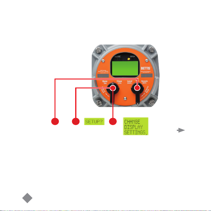
Turn the selector knob to the STOP position then toggle the control knob in rapid succession to YES, then
NO, then YES, then NO and release. The setup icon will be displayed on the display module and “SETUP?“
will be displayed on the message center. Rotate the control knob to YES. The message center will display
“CHANGE DISPLAY SETTINGS”.
2 3
YES,
NO,
YES,
NO
Release
YES
Continued on
next page
10
Page 11

Changing the Valve Settings
appears.
Continued from
previous page
4 5
NO
Until
Answer NO to the Setup prompts until “CHANGE SETTINGS?” appears. Answer YES. “ACCEPT PASSCODE
CHARACTER 1?X” appears. The factory default passcode is 000. Do not change the password without
recording the new password.
YES
Continued on
next page
11
Page 12

Changing the Valve Settings
YES
If passcode
character is
correct...
Enter Passcode
Continued from
previous page
Continued on
next page
OR
6
Use the control knob and answer YES if the passcode character is correct. If not, use NO to advance
incrementally to the correct character. Repeat this process until three passcode characters are entered.
7
NO
...to advance
to correct
character.
12
Page 13

Changing the Valve Settings
YES
Setting Limits
Continued from
previous page
8
Advance to the “SET VALVE TRAVEL LIMITS” prompt and answer YES. Proceed to set limits.
9
NO
13
Page 14

Network Controlled
YES
(CAM and Controlinc® option required)
1
REMOTE
In the “SETUP” mode advance to “NETWORK SETUP?” using the selector knob in the REMOTE position.
Answer YES. Hold the control knob in the NO position until the correct address appears. Answer YES. Unit
is now network controlled. If other conguration changes are needed, please see the TEC2 Installation &
Operation Manual (E2K-405-0614), which can be found at www.emerson.com/bettis.
2 3
NO
Until...
YES
14
4
NO
Until
correct
address...
5
Page 15

Saving the Changes
C
?
1
SAVE
HANGES
YES
Advance to the “SAVE CHANGES?” prompt and answer YES to save the changes.
2
NO
15
Page 16

World Area Configuration Centers (WACC) offer sales support,
service, inventory and commissioning to our global customers.
Choose the WACC or sales office nearest you:
NORTH & SOUTH AMERICA
19200 Northwest Freeway
Houston TX 77065
USA
T +1 281 477 4100
Av. Hollingsworth
325 Iporanga Sorocaba
SP 18087-105
Brazil
T +55 15 3413 8888
ASIA PACIFIC
No. 9 Gul Road
#01-02 Singapore 629361
T +65 6777 8211
No. 1 Lai Yuan Road
Wuqing Development Area
Tianjin 301700
P. R. China
T +86 22 8212 3300
For complete list of sales and manufacturing sites, please visit
www.emerson.com/actuationtechnologieslocations
Or contact us at info.actuationtechnologies@emerson.com
MIDDLE EAST & AFRICA
P. O. Box 17033
Jebel Ali Free Zone
Dubai
T +971 4 811 8100
P. O. Box 10305
Jubail 31961
Saudi Arabia
T +966 3 340 8650
24 Angus Crescent
Longmeadow Business Estate East
P.O. Box 6908 Greenstone
1616 Modderfontein Extension 5
South Africa
T +27 11 451 3700
EUROPE
Holland Fasor 6
Székesfehérvár 8000
Hungary
T +36 22 53 09 50
Strada Biffi 165
29017 Fiorenzuola d’Arda (PC)
Italy
T +39 0523 944 411
www.emerson.com/bettis
©2018 Emerson. All rights reserved.
The Emerson logo is a trademark and service
mark of Emerson Electric Co. BettisTM is a mark
of one of the Emerson family of companies.
All other marks are property of their respective
owners.
The contents of this publication are presented
for information purposes only, and while every
effort has been made to ensure their accuracy,
they are not to be construed as warranties or
guarantees, express or implied, regarding the
products or services described herein or their
use or applicability. All sales are governed by
our terms and conditions, which are available
on request. We reserve the right to modify or
improve the designs or specications of our
products at any time without notice.
 Loading...