

Page 1

Installation Guide FieldQ
DOC.IG.QC41.1 Rev. 3 August 2018
FieldQ Integrated Control Modules
QC41 24VDC
QC42 115VAC
QC43 230VAC
FieldQ
Page 2

Installation Guide FieldQ
August 2018 DOC.IG.QC41.1 Rev. 3
1 Applicable Control modules:
QC41 - 24VDC - Weather Proof
- Explosion Proof / Flame proof
QC42 - 115VAC - Weather Proof
- Explosion Proof / Flame proof
QC43 - 230VAC - Weather Proof
- Explosion Proof / Flame proof
Note:
Both executions can be equipped with one or two
pilot valves:
* One pilot valve is default and suitable for normal
operation of double acting or spring return
actuators.
* Two pilot valves are required for Fail in Last
Position function on double acting actuators.
The enclosures of both Weather Proof and Explosion
Proof / Flame proof modules, have a IP66 or NEMA
4X, ingress protected rating.
2 Before starting
* Actuator must be isolated both pneumatically
and electrically before any (dis)assembly is
begun.
* Installation, adjustment, putting into service,
use, assembly, disassembly and maintenance of
the control module must be done by qualified
personnel.
* Be sure that the actuator is correctly mounted
before connecting air supply and electrical
wiring (see Installation & Operation Manual
FieldQ Valve Actuator, DOC.IOM.Q.E)
* Check the module label for the right execution
(see figure 2.2)
* Check the type of actuator: single or double
acting (see figure 2.2).
* For mechanical installation of the module see
installation instruction leaflet DOC.QC4.MTI.1,
as shipped with the module.
2.1 Intended use
The FieldQ actuator is an integrated concept for
the automation of quarter turn valves, dampers or
other quarter turn applications. It consists of two
basic parts (see figure 2.1):
1. Pneumatic actuator
2. Control Module
The control module allows operation of the
actuator and supplies position feedback signals.
1
2
Fig. 2.1: Check proper mounting before connecting air
supply and electrical wiring.
2
Control Module Type Label =
24VDC
QC41..WP.. = Weather Proof
QC41..Px.. = Explosion-/Flame proof
115VAC
QC42..WP.. = Weather Proof
QC42..Px.. = Explosion-/Flame proof
230VAC
QC43..WP.. = Weather Proof
QC43..Px.. = Explosion-/Flame proof
Actuator Type Label =
QS xxxx = Single acting (Spring Return)
QD xxxx = Double acting
Fig. 2.2 Identification
Page 3

Installation Guide FieldQ
DOC.IG.QC41.1 Rev. 3 August 2018
2.2 Mechanical alignment and mounting of
the control module
The control module is equipped with an alignmentedge on top of the module. This allows easy
alignment and mounting of the control module on
to the actuator housing.
Procedure: (see figure 2.3)
1. First take care that both mating faces from the
actuator and control module are clean and free
of dirt.
2. Check if the module has the required function
3. Remove the transparent film from the control
module.
4. Ensure seals are placed correctly.
5. Level the screws with the surface.
6. Place the alignment-edge (1) of the control
module at the top of the pneumatic interface.
7. Flip the module down taking care that the IPT
Probe (see fig 5; nr.2) on the actuator fits in the
mating hole on the control module and loosely
place the screws.
8. Tighten screws according force in sequence.
Tightening moments
The Control Module should be fastened by using
an Allen key and applying the following tightening
moments:
- Allen Key No 5: 6.1 to 6.6 Nm (54 - 58.4
In.lbs)
Alignment-edge
Alignment-edge
IPT probe
Fig. 2.3 Alignment and mounting of control
module to actuator
3
Page 4

Installation Guide FieldQ
August 2018 DOC.IG.QC41.1 Rev. 3
3 Pneumatic connections
IMPORTANT
1 The actuator/valve combination can move
after connecting the air supply.
2 Ensure that the QC4x control modules are
mounted properly to the actuator to achieve
good functioning and the required ingress
protection, before connecting the air supply.
3 Check that the maximum supply pressure
P
= 8bar/116Psi
max
4 Be sure that the minimum required supply
pressure for the application is available at the
actuator.
5 Take appropriate measures to prevent
condensation or moisture to entering the
actuator or the control module. Condensation
or moisture can damage these components
and can result in failures.
6 The exhaust ports Ra and Rb on the module
(see figure 3.1) are shipped from the factory
with transport protection.
* If ingress protection IP66 or NEMA 4X is
required, appropriate connections must be
used in exhaust ports Ra & Rb.
3.1 Operating media :
* Air or inert gasses.
* Air filtered at 50 micron.
* Dew point 10 K below operating temperature.
* For subzero applications take appropriate
measures.
3.2 Single acting (spring return) or Double
acting actuator :
1 Remove the transport sticker from the air supply
(Ps).
2 Connect air supply to por t (Ps).
Single acting
Control
Module cover
Double acting
Fig. 3.1: Pneumatic connections
Ra
Ps
1/4” BSP or
1/4” NPT
Ra
Rb
Ps
1/4” BSP or
1/4” NPT
4
Page 5

Installation Guide FieldQ
DOC.IG.QC41.1 Rev. 3 August 2018
4 Electric Connections
The conventional Control Module contains a pilot
valve for controlling the actuator and switches for
position feedback.
WARNING:
* If the Control Module is used in a manner not
specified by the manufacturer, the protection
provided by the equipment may be impaired.
* For electrical safety the marked protective
conductor terminal inside or outside the
Control Module housing shall be connected to
earth.
* If required, mount earth wire (1) between top
(2) and stainless steel washer (3) of earth wire
connection (see figure 4.2).
* To fulfill the electrical safety regulations
according IEC 61010-1, a switch and circuitbreaker shall be included in the building
installation. It is advised to indicate the
location of the circuit breaker by means of a
label on or nearby the installed
FieldQ modules. The disconnection switch or
circuit breaker shall disconnect all currentcarrying conductors.
* Heat resistant cable and cable glands shall be
used, suitable for temperatures of at least 80°C
* Use and mount cable glands as required by
national or local legislation.
* If IP66 or NEMA 4X ingress protection is
required, then the electrical entries must be
fitted with devices rated IP66 or NEMA 4X.
Electrical safety requirements:
Use In- and outdoor.
Altitude
Maximum relative humidity
Mains supply
fluctuation
Over voltage
category
Pollution degree
Temperature see table 4.1
Operating full power available
up to 2000 meter (6000 feet).
80% for temperatures up to 31°C
(87.8°F) decreasing linearly to
50% relative humidity at 40°C
(104°F).
up to ±10% of nominal voltage
II
2 (3 when the cover remains
closed)
Caution! :
Risk of electric shock
* Installation, adjustment, putting into service,
use, assembly, disassembly and maintenance
of the control module is strictly reserved to
qualified personnel.
* Do not attempt to install or repair any electric
device without shutting off incoming power.
Terminals
Lockable
Module cover
Electrical entries:
3/4”NPT
or M25
1/2”NPT
or M20
Switch terminals
Control Module
Type Label
Pilot valve
terminals
Option: Manual
control
Option: Additional
manual control for
“Fail in Last Position”
Fig. 4.1 Terminal connections behind cover.
Fig. 4.2 Earth wire connection
5
Page 6

Installation Guide FieldQ
August 2018 DOC.IG.QC41.1 Rev. 3
4.1 FieldQ QC4x modules
Hazardous Area instructions
IMPORTANT
All installation, inspection, maintenance and
repair of the equipment should be performed
by suitably trained personnel.
The Control Modules must not be used in
atmospheres that contains acetone, ethyl
acetate or acetic acid vapors.
4.1.1 ATEX/IECEx Intended use
The Control Modules QC4x..P5.. of the
FieldQ pneumatic actuator is a Group II category
2 (ATEX) equipment with protection level Gb,
Db (IECEx) and intended for use in areas in which
explosive atmospheres caused by mixtures of air
and gases, vapors, mists or by air/dusts are likely to
occur.
The pneumatic actuator part, together with the
pneumatic module part of the FieldQ pneumatic
actuators is a Group II category 2 equipment
and intended for use in areas in which explosive
atmospheres caused by mixtures of air and gases,
vapors, mists or by air/dusts are likely to occur.
Therefore it may be used in hazardous area
classified Zones 1, 2 (Gasses) and/or 21, 22 (Dust).
Control Module Type Label =
QC41·MP5MSA1·0040UQP000
Pneumatic action
Switch cartridge
Fig. 4.4 Switch cartridge and pneumatic action
identification
2. Substitution of component may impair
suitability for Zone 2 Increased Safety.
3. Do not open cover of terminal compartment
when an explosive atmosphere is present.
4. Cleaning this housing by rubbing should be done
in a non-hazardous area,
5. Potential electrostatic charging hazard, clean
only with a damp cloth - danger of propagating
discharge.
6. The apparatus shall be installed in such a way
that the risk from electrostatic discharges and
propagating brush discharges caused by rapid
flow of dust is avoided.
7. All grounding and bonding installation
requirements must be addressed.
8. The cable entry device and the closing elements
of unused apertures must be of a certified
flameproof type, suitable for the conditions of
use and correctly installed.
9 Blind plugs or cable gland shall be engaged
into the cable entries minimal 5.5 threads for
M20x1.5 entries and minimal 5 threads for NPT
entries.
10. Certified Ex t cable glands shall be use in a dust
environment.
11. Heat resistant cable and cable glands shall be
used, suitable for temperatures of at least 80°C
12. The maximum temperature of the supply
air must stay below the maximum ambient
temperature as marked on the control module
(see table 4.1).
13. The maximum temperature of the base actuator
must stay below the maximum ambient
temperature as marked on the control module
(see table 4.1).
14. Contact your local Emerson representative for
information on the dimensions of the flame
proof joints.
15.Precaution shall be taken to avoid danger of
ignition due to electrostatic charges on the
marking plate of the enclosure.
4.1.2 Hazardous area Special safety instructions
for safe use
1. For ATEX, all installation, inspection,
maintenance and repair must be done by
suitably trained personnel. For information refer
to EN60079-14, EN60079-17, EN60079-19.
6
4.1.3 FM Special safety instructions
1. Metric entries are not allowed. Metric entries are
for IECEx or ATEX installations only.
2. Wiring must be done according NEC 500.
Page 7

Installation Guide FieldQ
DOC.IG.QC41.1 Rev. 3 August 2018
Table 4.1 Ambient and maximum surface temperature rating.
Configuration Temperature (°C)
Max.
Power
dissipa-
tion
F 7.2W
Switch cartridge
M = Mechanical switches
G = Mechanical switches (gold contacts)
C = 3 wire PNP proximity switch
O = 3 wire NPN proximity switch
N = 2 wire proximity switch
H = 2 wire proximity switch
(1
(1
(2
Min.
ambient
-25°C /
-13°F
-25°C /
-13°F
-25°C /
-13°F
Max.
ambient
+60°C /
+140°F
+60°C /
+140°F
+60°C /
+140°F
Max.
Surface
+80°C /
176°F
+80°C /
176°F
+80°C /
176°F
Class
T6/T4
T6/T4
T6/T4
Module type
QC41 (24VDC)
QC42, QC43
(115 or 230VAC)
QC42, QC43
Switch
cartridge
O,C,N,H
M, G
Pneumat-
ic action
S,D,F 3.6W
S,D 3.6W
(1
(115 or 230VAC)
Notes:
1 1x or 2x 24VDC pilot valves, or 1x 115/230 VAC pilot valve
2 2x 115 or 230 VAC pilot valves
Pneumatic action
S = Spring Return (Single acting).
D = Double acting.
F = Double acting (Fail in Last Position)
4.1.4 Applied IECEx standards
For FieldQ Control Module:
- QC4x...P5... (x = 1, 2 or 3)
the following standards are applied:
- IEC 60079-0: 2017
- IEC 60079-1: 2014
- IEC 60079-31: 2013
4.1.5 Product marking;
Each control module is marked with the applicable ambient temperature marking (see table 10.1).
IECEx hazardous or Classified Location:
Ex db IIB + H2 T4/T6 Gb
EX td IIIC T80°C Db
IECEx DEK 11.0043X
ATEX hazardous or Classified Location:
II 2G Ex db IIB + H2 T4/T6 Gb
II 2D EX td IIIC T80°C Db
11ATEX0092 X
FM hazardous or Classified Location:
CL I, II, III, DIV 1
Groups BCDEFG, T4/T6,
Type 4X
CL I, ZN 1, IIB+H2 T4/T6
CSA hazardous or Classified Location:
Class I, II, III, DIV 1
Groups CDEFG, T4/T6,
Type 4X
Ex d IIB+H2 T4/T6
DIP A21 TA 80°C
7
Page 8

Installation Guide FieldQ
August 2018 DOC.IG.QC41.1 Rev. 3
4.2 Connecting Pilot valve(s)
The Control Module can be equipped with one or
two pilot valves:
* One pilot valve is default and suitable for normal
operation of double acting or spring return
actuators
* Two pilot valves are required for Fail in Last
Position for double acting actuators.
IMPORTANT
For hazardous area installations see instructions in
paragraph 4.1
1. Before connecting the pilot valve, check the
voltage on the control module label.
2 Remove control module cover (see figure 4.1).
3 Guide the cable(s) through the electrical
entry(ies).
- Use and mount cable glands as required by
national or local legislation.
4 For normal operation, make the electrical
connections as shown in figure 4.5.
For double acting actuators with Fail in
Last Position function, make the electrical
connections as shown in figure 4.6
5 Mount the control module cover to the housing
(see figure 4.1) or continue with chapter 5. Take
care that the cover seal is in place to comply to
dust and water tightness according to IP66 or
NEMA4X.
6 Lock the cover in position by turning the lock
screw in, until it blocks.
4.2.1 Tools
Table 4.2 Tool table
For terminals Screw driver 0.6 x 3.5
Cover lock screw Allen key nr 2
Cable range:
0.33 - 2.5mm2 or
22 - 12AWG
Fig. 4.5 Default Pilot valve wiring connections
Cable range:
0.33 - 2.5mm2 or
22 - 12AWG
Fig. 4.6 Pilot valve wiring connections for
Fail in Last Position
8
Page 9
Installation Guide FieldQ
-3° 15° 75° 93°
0° 90°
DOC.IG.QC41.1 Rev. 3 August 2018
4.3 Connecting Mechanical Feedback switches
1. Before connecting the switches, check the
model code on the Control Module label.
QCXX.xxxMxx = Mechanical switches
QCXX.xxxGxx = Mechanical switches
(gold plated)
2 Guide the cable(s) through the electrical
entry(ies).
- Use and mount cable glands as required by
national or local legislation.
3. Make connections as shown in figure 4.8 and
table 4.3/4.4
4. Mount the Control Module cover. Take care that
the cover seal is in place to comply to dust and
water tightness according to IP66 or NEMA4X.
IMPORTANT
For hazardous area installations see instructions in
paragraph 4.1
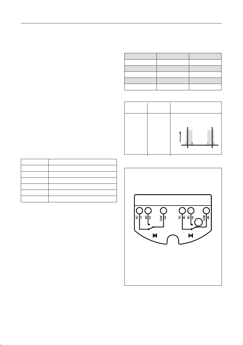
Table 4.3 Mechanical switches
Option code M
Option code G (gold contacts)
Typ e Mechanical
Voltage M: 277 VAC or 250VDC (maximum)
G: 125 VAC or 30VDC (maximum)
Contacts NO and NC
Temperature See table 4.1
Notes:
1. The mechanical (M-type) switches are rated for
3 A with inductive load.
2 The mechanical (G-type) switches have gold
contacts. For applications where the benefits
of gold contacts are required, the maximum
current is 1 A.
Table 4. 4 Maximum currents mechanical switches
Switch voltage M type switch G type switch
125 VAC 10 A (3 A1) 0.1 A
2
250 VAC 10 A (3 A1) 30 VDC 0.5 A 0.1 A
2
125 VDC 0.5 A 250 VDC 0.25 A -
Contact Switch signal and adjustable
Normally
Open
Contacts
Switch
operation
Switched
Unswitched
switch
Signal
switch range
Close
Rotation
Open
Switch
Fig 4.7 Adjustable switch range and factory settings
Wiring diagram:
- M = Mechanical
- G = Mechanical, gold contacts
Open Close
Cable range : 0.33 - 2.5mm2 or 22 - 12AWG
1 Wiring diagram shown, is applicable for actuators with
assembly code “CW”. For actuators with assembly code “CC”
(reverse acting) the “Open” and “Closed” switch connections
are also reversed.
2 Wiring diagram is shown in the actuators mid-stroke position.
Fig 4.8 Wiring diagram mechanical switches
9
Page 10

Installation Guide FieldQ
-3° 15° 75° 93°
0° 90°
3mA
1mA
-3° 15° 75° 93°
0° 90°
3mA
1mA
≥ 3mA
≤ 1 mA
≥ 3mA
≤ 1 mA
-3° 15° 75° 93°
0° 90°
August 2018 DOC.IG.QC41.1 Rev. 3
4.4 Connecting 2-Wire proximity switches
1. Before connecting the switches, check the
model code on the Control Module label.
QCXX.xxxNxx = 2-Wire NAMUR proximity
QCXX.xxxHxx = 2-Wire 230VAC proximity
2 Guide the cable(s) through the electrical
entry(ies).
- Use and mount cable glands as required by
national or local legislation.
3. Make connections as shown in figure 4.11 and
table 4.5 or 4.6.
4. Mount the Control Module cover. Take care that
the cover seal is in place to comply to dust and
water tightness according to IP66 or NEMA4X.
IMPORTANT
For hazardous area installations see instructions in
paragraph 4.1.
Table 4.5 2-Wire NAMUR proximity switches
Option code N
Typ e 2-wire inductive, normally closed
Voltage 8 VDC nominal
Output Unswitched: > 3mA
Switched: < 1mA
Temperature See table 4.1
Compliant to DIN EN 60947-5-6 (NAMUR)
Table 4.6 2-Wire 230 VAC proximity switches
Option code H
Voltage 20...250VAC / 10...300VDC
(50...60 Hz AC)
Current Maximum 100 mA
Peak 0,9A (20ms/0,5Hz)
Leakage < 1.7 mA
Temperature See table 4.1
Switch
2-Wire 115V
proximity
switch
Switch
operation
Switched
Unswitched
Switch signal and adjustable
switch range
Close
switch
Signal
Rotation
Fig 4.9 Switch characteristics 2-wire 230VAC
proximity switch
Switch
operation
Open Switch
Unswitched
Switched
Close Switch
Unswitched
Switched
Switch signal and adjustable switch range
2-wire NAMUR proximity switch
Rotation
3mA
≥ 3mA
1mA
-3° 15° 75° 93°
≤ 1 mA
0° 90°
Rotation
Fig 4.10 Switch characteristics 2-wire NAMUR
proximity switch
Open
Switch
10
Page 11

Installation Guide FieldQ
DOC.IG.QC41.1 Rev. 3 August 2018
Wiring diagram:
- 2-Wire NAMUR proximity switches
- 2-Wire 230 VAC proximity switches
L-
1
2
1
Cable range : 0.33 - 2.5mm2 or 22 - 12AWG
1 Wiring diagram shown, is applicable for actuators with assembly
code “CW”. For actuators with assembly code “CC” (reverse
acting) the “Open” and “Closed” switch connections are also
reversed.
2
Open
3
L+
5
L-
4
2
1
Close
6
L+
Fig 4.11 Wiring diagram 2-Wire proximity switches.
11
Page 12

Installation Guide FieldQ
16
-3° 15° 75° 93°
0° 90°
August 2018 DOC.IG.QC41.1 Rev. 3
4.5 “3-Wire” proximity switches
1. Before connecting the switches, check the
Switch
Switch
operation
model code on the function module label.
QCXX.xxxOxx = 3-Wire PNP proximity
QCXX.xxxCxx = 3-Wire NPN proximity
2 Guide the cable(s) through the electrical
entry(ies).
- Use and mount cable glands as required by
national or local legislation.
3. Make connections as shown in figure 4.12 and
3-Wire PNP or
NPN proximity
switch
Switched
Unswitched
table 4.7
4. Mount the Control Module cover. Take care that
the cover seal is in place to comply to dust and
water tightness according to IP66 or NEMA4X.
IMPORTANT
For hazardous area installations see instructions in
chapter X
Fig. 4.12 Switch characteristics 3-wire PNP or NPN
proximity switches.
Wiring diagram:
3-Wire proximity switches PNP
Table 4.7 3-Wire proximity switches
Option code O, V3 PNP
Option code C, V3 NPN
Function Make
Voltage 10 - 30V
Current 100 mA maximum
0 ... 0.5 mA typical (Off-state)
Temperature See table 4.1
L- L+ L- L+
3
4
1
PNP
Open
Wiring diagram:
3-Wire proximity switches NPN
Switch signal and adjustable
switch range
Close
switch
Signal
32
4
Close
Rotation
5
3
4
1
Open
Switch
12
L- L+ L- L+
1
3
4
1
3
2
5
4
3
4
1
NPN
Open Close
Cable range : 0.33 - 2.5mm2 or 22 - 12AWG
1 Wiring diagram shown, is applicable for actuators with
assembly code “CW”. For actuators with assembly code “CC”
(reverse acting) the “Open” and “Closed” switch connections
are also reversed.
Fig. 4.12 Wiring diagram 3-wire PNP or NPN
proximity switches.
6
Page 13

Installation Guide FieldQ
15°
max
15°
max
DOC.IG.QC41.1 Rev. 3 August 2018
5 Limit switch setting
5.1 Factory settings
Mechanical stroke : 90°±0.5° (Actuator setting)
Switch points : ± 15° before each end of
stroke (open and closed
position, see fig 5.1).
Adjustable range : See chapter 4.2 for the
applicable switch type.
Closed
Switch points
Open
Factory settings
Fig. 5.1 Adjustable range and factory settings
If required the mechanical stroke and the limit
switch setting can be re-adjusted.
- For mechanical stroke adjustment please see
document DOC.IOM.Q.E, available from
www.FieldQ.com.
- For re-adjusting the limit switches, see
procedure below.
5.2 Before re-adjusting the limit switches.
IMPORTANT
* Before mounting the actuator on the valve, be
sure that both the actuator and the valve have
the same “open” or “closed” position.
* Set the Mechanical stroke before setting the
limit switches.
5.2.1 Pneumatic and electrical connections
Make pneumatic and electrical connections before
adjusting the limit switch setting. See chapter 3
and 4.
5.2.2 Switch point setting and valve rotation
direction.
The QC41, QC42 and QC43 are equipped with nonintrusive switch adjustment. The adjustment screws
are accessible behind a small shield in the front of
the module (see fig 5.3).
This means that the switch adjustment can be done
without opening the module.
Normally valves are “Closed” after a clock wise
rotation.
- In this case the top adjustment screw (see
fig. 5.3), sets the switch point of the “Closed”
position and bottom adjustment screw sets the
switch point of the “Open” position.
- When you have a valve that is “Open” after a
clock wise rotation, the position feedback will be
reversed.
The table below indicates which re-adjustment
screw and terminals are related to the “Open” or
“Closed” switch point setting (see fig 16).
Table 5.1 Re-adjustment screws
Re-
adjust-
ment
screw :
Terminals
Valve movement
“Close” after
a clock wise
rotation
“Open” af ter
a clock wise
rotation
Bottom 1, 2, & 3 Open position Close position
Top 4, 5, & 6 Close position Open position
13
Page 14
Installation Guide FieldQ
August 2018 DOC.IG.QC41.1 Rev. 3
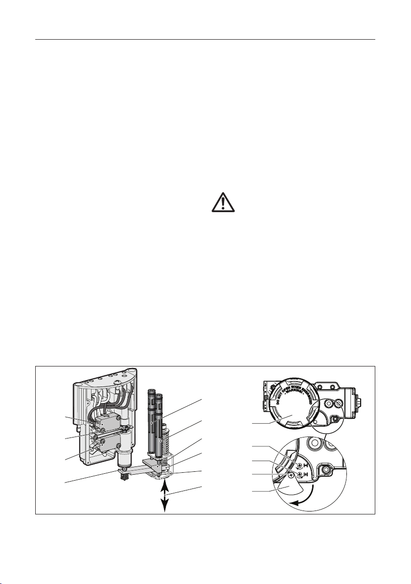
5.2.3 Working principles Switch Operating
Mechanism (see fig 5.2)
The Switch Operating Mechanism is intend to
operate the position feedback switches and allows
adjustment of the switch points in the open and
closed end positions. Factory setting is that the
switches are activated 15° before the end of the
open and closed stroke.
Switch Operation
The rotation of the actuators pinion operates the
IPT device (1) which results in a linear movement.
The linear movement of the IPT device operates
lever (3). The lever amplifies the linear movement
of the IPT device and operates the switch operating
rod (5). Dowel pin (6) in the rod operated the levers
of the open and closed switch elements (8 & 9).
The lever is of the “floating” type. When the IPT
device operates the lever, it moves completely
upwards until it meets the upper pivot block (4). At
this point the lever will tip over and pull down the
switch operating rod (5) and operates the bottom switch (7). When the IPT device moves back
the springs cause the lever to move completely
downwards until it meets the lower pivot block
(2). At this point the lever will tip over and push up
the switch operating rod (5) and operates the top
switch (8).
Switch point adjustment
The position of the lower pivot block (2) can be
changed by adjustment screw (10) and the position
of the upper pivot block (4) can be changed by
adjustment screw (9).
By adjusting the position of these pivot blocks the
switch points will be changed.
The adjustment screws (9 & 10) can be found
behind the shield (12) in front of the module. To
access the adjustment screws loosen the screw (11)
and rotate the shield (12) as shown.
Caution: Do not force the
adjustment screws when
resistance is felt.
During adjustment there are three situations
that can damage the adjustment screw head and
internal mechanisms when forcing the adjustment
screws.
1. Pivot block (2) will be blocked at bottom if screw
(10) is rotated too much counter clock wise.
2. Pivot block (3) will be blocked at top if screw (9)
is rotated too much clock wise.
3. Pivot blocks (2&3) will interfere with each other,
if the adjustment screws (9&10) are rotated too
much in the direction according to their related
arrows.
Situation 1 and 2 may happen in combination with
situation 3.
8
6
7
5
Fig. 5.2 Working principles Switch Operating Mechanism
14
10
9
4
3
2
1
15
10
11
12
H
E
W
N
N
E
E
N
N
I
P
N
R
G
A
E
O
!
W
R
-
-
T
G
O
I
N
O
D
Z
E
D
9
Page 15
Installation Guide FieldQ
DOC.IG.QC41.1 Rev. 3 August 2018
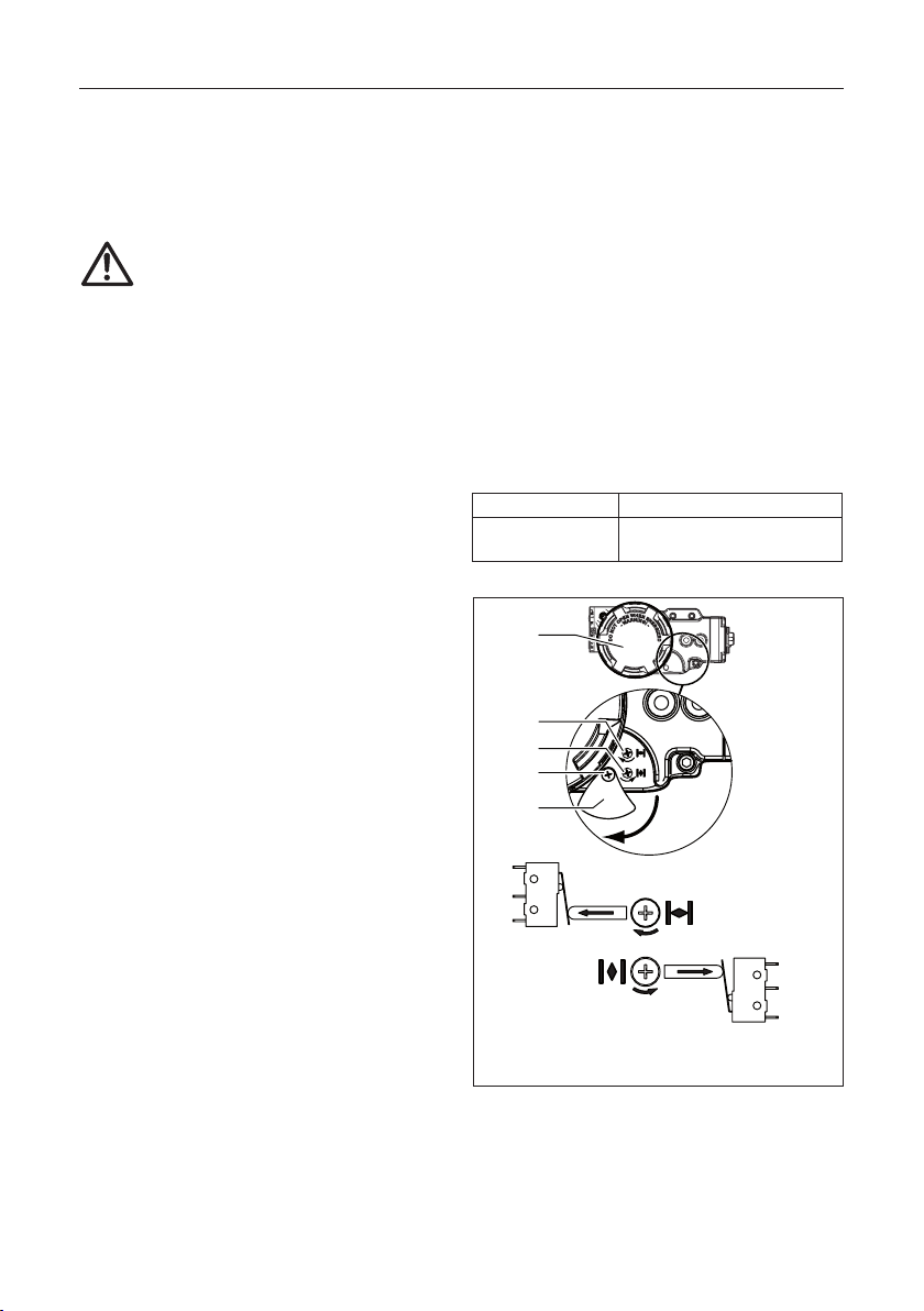
5.3 Re-adjustment of switch points
IMPORTANT
The procedure below assumes:
- That the actuator and control modules are
according the factory settings.
If the switch setting is somehow lost or
forgotten, then consult paragraph 6.3 to
set the switch point setting back to factory
setting.
- That the actuator / valve assembly is closed
after a clock wise rotation (see chapter 5.2).
Below procedure assures that the position feedback
complies more accurately with the valve position
and will set the switch point at approximately
4° before the end of the stroke.
To set and detect the switch point, use a multi
meter, connected to the switch terminals, to
measure
a resistance change as applicable per switch type
(see applicable wiring diagram in chapter 4.2). For
the proximity switches, you can use a proximity
switch tester.
Procedure (see fig 5.3):
1. Remove cover (15) and loosen the screw (11) of
the shield (12) and turn the shield down.
Closed Position:
2. Move the actuator/valve assembly to the closed
position by removing the control signal from
pilot valve terminal 8 and 9 (see § 4.1).
3. Turn top screw (10) counter clock wise (do not
force the adjustment screw) until the switch
trips to the “off state” (no signal).
4. Turn top screw (10) clock wise (do not force the
adjustment screw) until the switch trips to the
“on state”. This position represents the actual,
mechanical “closed” position of the valve.
5. Turn the screw minimal a 1/2 turn clock wise.
The “closed” position switch point is now set.
Open Position:
6. Move the actuator to the open position by
applying the applicable voltage to pilot valve
terminal 8 and 9 (see § 4.1).
7. Turn bottom screw (9) clock wise (do not force
the adjustment screw) until the switch trips to
the “off state” (no signal).
8. Turn bottom screw (9) counter clock wise (do
not force the adjustment screw) until the
switch trips to the “on state”. This position represents the actual “open” position of the valve.
9. Turn the screw minimal a 1/2 turn counter clock
wise. The “open” position switch point is now
set.
10. Turn the shield (12) back over the adjustment
screws and fasten it with the screw (11) and
mount the main round cover back in place.
Table 5.2 Tool table
Shield screw Cross slotted Phillips nr. PH2
Adjustment screws 0.6 x 3.5 or
Cross slotted Phillips nr. PH2
H
E
W
N
N
E
E
N
N
I
P
N
R
G
A
E
O
!
W
R
-
-
T
G
O
I
Z
N
E
O
15
D
D
10
9
11
12
“Closed”
Switch point adjustment
“Open”
Switch point adjustment
Note:
360° rotation of adjustment screw is
±8° adjustment of switch point.
Fig. 5.3 Re-adjustment screws for “Open” and
“Closed” position feedback
15
Page 16

Installation Guide FieldQ
August 2018 DOC.IG.QC41.1 Rev. 3
6 Trouble shooting
5.4 Check operation
5.4.1 Default (single) pilot valve
1 Connect pressure according chapter 3 and a
control signal to terminals (7) 8 and 9 according
§ 4.1 figure 4.3.
2 Actuator moves to “Open” position. “Open”
limit switch is activated and “Close” limit switch
is deactivated.
3 Remove voltage from terminals 9 and 8.
4 Actuator moves to “Close” position. “Close”
limit switch is activated and “Open” limit switch
is deactivated.
6 Mount the cover to the Control Module
(see fig. 4.1).
5.4.2 Dual pilot valve (Fail in Last Position)
operation
1. Connect pressure according chapter 3 and a
control signal to terminals (7) 8 and 9 according
§ 4.1 figure 4.4.
2. Actuator moves to “Open” position. “Open”
limit switch is activated and “Close” limit switch
is deactivated.
3. Remove voltage from terminals 9 and 8.
4. Actuator Stays in the “Open” position.
5. Connect pressure according chapter 3 and
a control signal to terminals (10) 11 and 12
according § 4.1 figure 4.4.
6. Actuator moves to “Closed” position. “Close”
limit switch is activated and “Open” limit switch
is deactivated.
7. Remove voltage from terminals 9 and 8.
8. Actuator Stays in the “Closed” position.
9. Mount the cover to the Control Module
(see fig. 4.1).
6.1 The “Open” and “Closed” position
feedback signals are reversed from the
actual valve positions.
1 Check if the actuator is correctly mounted to the
valve.
Before mounting the actuator on the valve, the
actuator and the valve should have the same
“open” or ‘closed” position (see Installation &
Operation Manual FieldQ Valve Actuator DOC.
IOM.Q.E).
2 Some valves may be operated in such a way that
they are:
- “Open” after a clock wise rotation and
- “Closed” after a clock wise rotation.
3 Please see § 5.2 for setting the “Open” and
“Closed” position feedback signals
6.2 The actuator does not give (good) position
feedback signals.
1 Check if the actuator is correctly mounted to the
valve.
2 Re-adjust the limit switch setting as per chapter
5.3
6.3 Factory setting of the switch points.
IMPORTANT
The procedure below assumes:
- That the actuator / valve assembly is closed
after a clock wise rotation (see also § 5.1).
- The control module is pneumatically and elec-
trically connected according chapter 3 and 4.
This procedure sets the switch point settings of the
switches, back to the factory settings (±15° before
each end of stroke), assuming a mechanical stroke
of 90°±0.5° of the actuator.
To set and detect the switch point, use a multi meter, connected to the switch terminals, to measure a
resistance change as applicable per switch type (see
applicable wiring diagram in chapter 4.2). For the
proximity switches, you can use a proximity switch
tester.
16
Page 17

Installation Guide FieldQ
DOC.IG.QC41.1 Rev. 3 August 2018
7 Maintenance
Procedure (see fig 5.3):
1. Remove cover (15) and loosen the screw (11) of
the shield (12) and turn the shield down.
Closed Position:
2. Move the actuator/valve assembly to the closed
position by removing the control signal from
terminal 8 and 9 (see § 4.1).
3. Turn top screw (10) counter clock wise maximum 20 turns, (do not force the adjustment
screw) until the switch trips to the “off state”
(no signal).
4. Turn top screw (10) clock wise 1 3/4 turn (do not
force the adjustment screw).
The “closed” position switch point is now set to
factory setting.
Open Position:
5. Move the actuator to the open position by applying the applicable voltage to terminal 8 and 9
(see § 4.1).
6. Turn bottom screw (9) clock wise maximum 20
turns, (do not force the adjustment screw) until the switch trips to the “on state” (no signal).
7. Turn bottom screw (9) counter clock wise 1 3/4
turn (do not force the adjustment screw) The
“open” position switch point is now set to factory setting.
8. Turn the shield (12) back over the adjustment
screws and fasten it with the screw (11) and
mount cover (15) back in place.
IMPORTANT
Do not force the adjustment screws
During switch point adjustment, do not force the
adjustment screws when you feel an obstruction.
Forcing the adjustment screws can damage the
cross head of the adjustment screw.
The FieldQ Control Modules are designed to operate
without maintenance. For any further maintenance
to the actuator see Installation & Operation Manual
FieldQ Valve Actuator, DOC.IOM.Q.E or contact
your local FieldQ representative.
Installation, adjustment, putting into service, use,
assembly, disassembly, maintenance and repair
of the Control Module must be done by qualified
personnel.
Note:
This product is only intended for use in large-scale
fixed installations excluded from the scope of
Directive 2011/65/EU on the restriction of the use
of certain hazardous substances in electrical and
electronic equipment (RoHS 2).
8 Optional Controls
8.1 Manual Control options
(see figure 8.1)
For commissioning, emergency or maintenance
purposes, the FieldQ can be supplied with one or
two Manual Control options. These can operate the
pilot valve(s) inside the module and as such operate
the actuator, when there is air pressure available,
but no control signal or power supply.
Location for 2nd
Lock
Unlock
45°
Manual Control
On
Off
Default location
of Manual Control
Fig. 8.1 Local Manual Control options
8.1.1 Mounting Manual Control
1 To add a Manual Control, remove the plug(s)
in front of the module and turn in the Manual
Control.
- For normal operation the module should be
fitted with one Manual Control.
- For Double Acting with a Fail-in-Last-Position
function, two Manual Control can be fitted.
17
Page 18

Installation Guide FieldQ
August 2018 DOC.IG.QC41.1 Rev. 3
8.1.2 Manual Control operation
1 The Manual Control has a “Push & Lock”
function:
- To operate the Manual Control, use a screw
driver, push to activate and release to deactivate the pilot valves.
- If required turn it 45°, to lock it in position
and keep the actuator in its operated state.
2 In case of a Fail in Last Position configuration
with two manual controls:
- The manual control on the right side (default
location) will pressurize the central air
chamber and cause the actuator to rotate
counter clock wise. For reverse acting FieldQ
actuators (Assembly code CC) the actuator
will rotate clock wise.
- The manual control on the left side (Location
for 2nd Manual Control) will pressurize the
end cap air chambers and cause the actuator
to rotate clock wise. For reverse acting FieldQ
actuators (Assembly code CC) the actuator
will rotate counter clock wise.
- In order to operate one of the manual
control, be sure the opposite manual control
is de-activated and unlocked.
3 It is possible to rotate the screw multiple cycles.
The unit will than toggle every 90° between
“locked” (1) and “unlocked” (0).
8.2 Speed control option
(see figure 8.2).
The FieldQ can be supplied with a Speed Control
option. One throttle is required for Spring Return
actuators and up to two for Double Acting
actuators.
The speed control throttle controls the air flow
in and out of an air chamber and as such limits
the speed of the “Opening” and “Closing” stroke
simultaneously.
8.2.1 Mounting Speed Control throttle(s):
1 Remove the plug(s) at the side of the module
and turn in the throttle (1).
2 Spring Return actuators: Use the top entry only.
3 Double acting actuators: Use both bottom and
top entries.
Spring Return:
Top entry only.
Double Acting:
Bottom and/or top
entries.
1
2
Fig. 8.2 Speed control operation
- For standard actuators, the top entry will
throttle the closing stroke.
- For standard actuators, the bottom entry will
throttle the opening stroke.
- For reverse acting actuators, the opposite
strokes will be throttled.
8.2.2 Adjusting Speed Control throttle(s):
1 Remove the nut cap (2).
2 Clockwise rotation of the adjustment screw
reduces the speed.
3 Counter clockwise rotation of the adjustment
screw increases the speed.
4 Replace the nut cap.
9 Related Information
Other documents containing information related to
the FieldQ Module include:
- Q1.604.10 FieldQ Control Module data
- DOC.IOM.Q.E Installation Operation &
These documents are available, in multiple
languages, for download from
www.emerson.com/fieldq
sheets
Maintenance Manual.
18
Page 19

Installation Guide FieldQ
DOC.IG.QC41.1 Rev. 3 August 2018
10 EU - Declaration of Conformity
Emerson Process Management,
6005 Rogerdale Road, Houston TX 77072 U.S.A.
Valve Automation Inc.
EU DECLARATION OF CONFORMITY
Issued in accordance with the
Low Voltage Directive 2014/35/EU
EMC Directive 2014/30/EU, Appendix 1
ATEX Directive 2014/34/EU
We hereby declare, that the products specied below meet the basic health and safety requirements of the
above mentioned European Directives.
Product description : FieldQ Control module Exd
Serial number : Each Control module has an identiable serial number
Year of Construction : Each Control module has an identiable Year of Construction
ATEX Directive 2014/34/EU
Types : QC41...P5... , QC42...P5... , QC43...P5...
ATEX Certicate No. : DEKRA 11ATEX0092 X
Marking :
Applicable standards : EN 60079-0 : 2012 +A11 : 2013, EN 60079-1 : 2014,
EN 60079-31 : 2014
Notied body : DEKRA Certication B.V., Notied body no : 0344
Meander 1051, 6825 MJ Arnhem, The Netherlands
II 2G Ex db IIB + H2 T4/T6 Gb
II 2D EX td IIIC T80°C Db
ROC nr 8300
Rev. 2
FieldQ
Low Voltage Directive 2014/35/EU, EMC Directive 2014/30/EU
Types : QC42...WP... , QC43...WP...
Applicable standards : EN 61010-1 : 2010
Note : The above listed ATEX certied products are excluded from the Low Volt-
age Directive
__________________________
Signed:
S. Ooi
Name:
Vice President, Rack & Pinion
Position:
SBU & Global Marcom
Emerson Process Management,
Valve Automation Group
2016-04-15
Date:
Houston TX, U.S.A.
Place:EN
19
Page 20

World Area Confi guration Centers (WACC) offer sales support,
service, inventory and commissioning to our global customers.
Choose the WACC or sales offi ce nearest you:
NORTH & SOUTH AMERICA
19200 Northwest Freeway
Houston TX 77065
USA
T +1 281 477 4100
Av. Hollingsworth
325 Iporanga Sorocaba
SP 18087-105
Brazil
T +55 15 3413 8888
ASIA PACIFIC
No. 9 Gul Road
#01-02 Singapore 629361
T +65 6777 8211
No. 1 Lai Yuan Road
Wuqing Development Area
Tianjin 301700
P. R. China
T +86 22 8212 3300
For complete list of sales and manufacturing sites, please visit
www.emerson.com/actuationtechnologieslocations
or contact us at info.actuationtechnologies@emerson.com
MIDDLE EAST & AFRICA
P. O. Box 17033
Jebel Ali Free Zone
Dubai
T +971 4 811 8100
P. O. Box 10305
Jubail 31961
Saudi Arabia
T +966 3 340 8650
24 Angus Crescent
Longmeadow Business Estate East
P.O. Box 6908 Greenstone
1616 Modderfontein Extension 5
South Africa
T +27 11 451 3700
EUROPE
Holland Fasor 6
Székesfehérvár 8000
Hungary
T +36 22 53 09 50
Strada Biffi 165
29017 Fiorenzuola d’Arda (PC)
Italy
T +39 0523 944 411
www.emerson.com/fi eldq
©2018 Emerson. All rights reserved.
The Emerson logo is a trademark and service mark of Emerson
Electric Co. FieldQ
companies. All other marks are property of their respective
owners.
The contents of this publication are presented for information
purposes only, and while every effort has been made to ensure
their accuracy, they are not to be construed as warranties or
guarantees, express or implied, regarding the products or
services described herein or their use or applicability.
All sales are governed by our terms and conditions, which
are available on request. We reserve the right to modify or
improve the designs or specifications of our products at any
time without notice.
TM
is a mark of one of the Emerson family of
FieldQ
 Loading...