

Page 1

Installation and Operation Manual
Bettis Controller Board C1415
C1415-0409 Rev. A
April 2009
Page 2

Page 3

Installation and Operation Manual
C1415-0409 Rev. A
Table of Contents
Section 1: General Description
1.1 Bettis C1415 DC Motor Controller Board ........................................................1
1.2 Wiring ............................................................................................................1
1.3 Jumpers .........................................................................................................2
1.4 Output Indicators ...........................................................................................3
1.5 Dip Switches ..................................................................................................3
1.6 Push Buttons ..................................................................................................3
1.7 Calibration Potentiometer ..............................................................................3
Section 2: Standard Setup and Operation
2.1 Order Outlined ...............................................................................................5
Section 3: Additional Control
3.1 Loss of Command Signal Setting (4-20 mA or 1-5 Vdc operation only) ...........7
3.2 Direct/Reverse Acting ....................................................................................7
3.3 Motor Restart Delay .......................................................................................7
3.4 Command Sensitivity .....................................................................................8
3.5 4-20 mA Output .............................................................................................8
3.6 Torque Trip Sensitivity ....................................................................................8
3.7 To Utilize the Command Switch ......................................................................8
Table of Contents
April 2009
Section 4: Specifications
4.1 D.C. Power ...................................................................................................10
4.2 Signal Inputs [Digitized to 8bit (1 in 255) accuracy] ......................................10
4.3 Signal Output [8 bit (1 in 255) accracy] ........................................................10
4.4 AC Motor Outputs ........................................................................................10
4.5 External Fuses ..............................................................................................10
4.6 Environmental .............................................................................................10
Section 5: Troubleshooting
5.1 Troubleshooting Problems ...........................................................................11
Table of Contents
I
Page 4

Section 1: General Description
April 2009
Installation and Operation Manual
C1415-0409 Rev. A
Section 1: General Description
C1415-04/09: This manual provides installation and operating information for the Bettis
Controller Board C1415. Should you have any questions about the controller that are not
covered under this manual, please contact an authorized Bettis Actuation Technologies
Center or Bettis Electric Division, 19200 Northwest Freeway Houston, Texas 77065,
United States +281 477 4100 (281) 477 2801.
1.1 Bettis C1415 DC Motor Controller Board
The Bettis C1415 DC Motor Controller board is an accurate, easy to use, multi-function
servo-board, intended for use with brush type motors. No calibration .equipment is
required to set the board. The basic concept of this controller is to read an external
command signal and compare it to a feedback signal from a potentiometer linked to
the output shaft. When the signals are not equal, the controller will energize either the
clockwise or counterclockwise motor circuit. This drives the actuator in the direction that
reduces the signal difference. Once the signals are equal, the controller opens the motor
circuit and the actuator is positioned properly, awaiting the next external command signal
change.
• The controller has the following options:
— Input power: 12 Vdc or 24 Vdc
— Input signals: 4-20 mA, 0-10 Vdc, 1-5 Vdc, or external command
— Output signal: 4-20 mA
— Loss of command signal: fail in place, fail CCW, fail CW
— Acting: direct acting (i.e. CW at 4 mA), reverse acting (i.e. CCW at 4 mA)
— Torque trip sensitivity: Variable, range dependent on actuator torque rating
— Motor restart delay: Variable from one to thirty-two seconds
— Command sensitivity (deadband): Variable, range depends on command
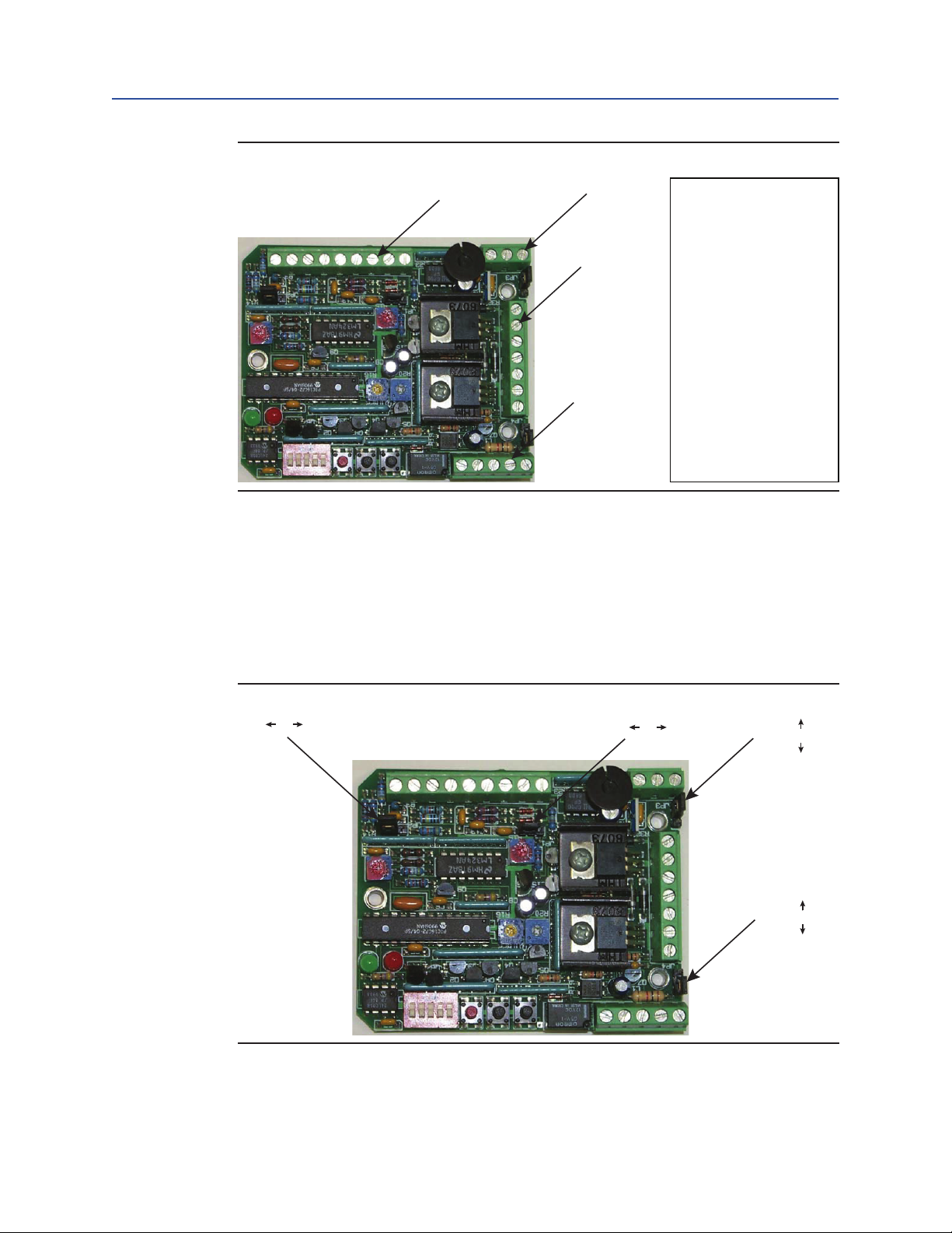
1.2 Wiring
There are four terminal blocks on the controller board, designated as TB1, TB2, TB3
and TB4. Terminal block TB1 is a 3 pole terminal block and is used for the (-) Vdc power
termination along with the external trip reset terminations. Terminal block TB2 is a 9 pole
terminal block and is used for all incoming and outgoing control signals. Terminal block
TB3 is a 5 pole terminal block and is used for limit switch terminations along with internal
trip indication output terminations. Terminal block TB4 is a 7 pole terminal block and is
used for the (+) Vdc power termination along with limit switch and motor terminations.
potentiometer
signal
1
General Description
Page 5
Installation and Operation Manual
Terminal Block TB1
<180° JP2 >180°
24 Vdc
c
c
Section 1: General Description
C1415-0409 Rev. A April 2009
Figure 1
1.3 Jumpers
There are four jumpers on the controller board designated as JP1, JP2, JP3 and JP4. JP1
provides the option for a 4-20 mA or 0-10 Vdc command signal input. JP2 is a sensitivity
jumper for the board’s internal calculation. JP3 and JP4 provide the option for 12 Vdc or 24
Vdc voltage inputs. See below for jumper congurations.
Terminal Block TB2
Terminal Block TB4
Terminal Block
TB1-1 > Reset
TB1-2 > Reset
TB1-3 > -DC Input
TB2-1 > Command Pot
TB2-2 > +4-20 mA/1-5 Vdc
TB2-3 > +0-10 Vdc
TB2-4 > - Signal Ground
TB2-5 > + Potentiometer
TB2-6 > Potentiometer Wiper
TB2-7 > - Potentiometer
TB2-8 > +4-20 mA Output
TB2-9 > -4-20 mA Output
TB3-1 > LS #1 NC
TB3-2 > LS #2 NC
TB3-3 > Internal Trip Relay NC
TB3-4 > Internal Trip Relay NO
TB3-5 > Internal Trip Relay Common
TB4-1 > LS #1 NO
TB4-2 > + Motor
TB4-3 > LS #1 Common
TB4-4 > +DC Input
TB4-5 > LS #2 Common
TB4-6 > -Motor
TB4-7 > LS #2 NO
Figure 2
4-20 mA JP1 0-10 Vdc
JP3
12 Vdc
12 Vd
JP4
24 Vd
General Description
2
Page 6

Section 1: General Description
Gree
April 2009
1.4 Output Indicators
There are two LEDs for visual reference during board operation. The red LED is lit as the
controller sends a signal to the motor to turn the actuator CCW or OPEN. The green LED
is lit as the controller sends a signal to the motor to turn the actuator CW or CLOSED. The
green LED is also a programming LED that is lit each time a setting is saved in memory. See
below for LED layout.
Figure 3
n LED
Installation and Operation Manual
C1415-0409 Rev. A
Red LED
1.5 Dip Switches
There are ve dip switches that are used to calibrate the controller. Conguration of these
dipswitches set the actuator and its functions.
1.6 Push Buttons
There are three push buttons on the controller board, PB1, PB2, and PB3. PB1 (black) operates the actuator in the CCW position when the controller is in the calibration mode. PB2
(black) operates the actuator in the CW position when the controller is in the calibration
mode. PB3 (red) is depressed each time a setting is required to be save into memory. See
below for pushbutton layout.
1.7 Calibration Potentiometer
There are two potentiometer used to calibrate the Motor Restart Delay, Sensitivity, and
Torque Trip. Once the potentiometer positions are stored in memory via the program
pushbutton, it can be moved without changing any of the settings. Thus allowing each
potentiometer to be used for multiple settings. The potentiometers are located as shown
below.
3
General Description
Page 7

Installation and Operation Manual
PB2 (Black)
Potentiometer P4
Section 1: General Description
C1415-0409 Rev. A April 2009
Figure 4
Dip Switches
SW4 (1-2-3-4-5)
Pushbutton
PB3 (Red)
Potentiometer
P3 (Fine Tune)
Pushbutton
(Primary Tune)
Pushbutton
PB1 (Black)
General Description
4
Page 8

Section 2: Standard Setup and Operation
April 2009
Installation and Operation Manual
C1415-0409 Rev. A
Section 2: Standard Setup and Operation
Please note that the following installation instructions must be followed in strict
accordance with the order outlined below.
2.1 Order Outlined
1. Verify controller board is wired up properly per the wiring diagram supplied with
the actuator.
2. Do not connect any command signals to the actuator at this time.
3. Verify all jumpers are set properly for your application. DO NOT change any
jumpers while the power is on. This may cause damage to the controller.
4. Switch dip switch #1 to the “ON” position and dip switches #2 through #5 to the
“OFF” position. This sets the controller for calibration mode.
5. Turn on the power to the actuator.
6. The next three series of steps will complete the basic setup of the controller. This
entails calibrating the potentiometer to the position of the output shaft along with
programming the end of travel setpoints into the controller.
7. This step is for eld installed kits only. Omit for factory installed boards!
To set the potentiometer, perform the following steps in order
a. Loosen the set screw in the potentiometer gear located on the output shaft.
b. Using PB1 and/or PB2, position the actuator halfway between the end of
travel limits.
c. Switch both dip switches #4 and #5 to the “ON” position.
d. Rotate the potentiometer shaft gear until the red and green LEDs are
illuminated.
e. Engage the potentiometer and output shaft gear teeth and tighten the
gear set screws.
f. Switch both dip switches #4 and #5 to the “OFF” position.
8. To set the end of travel CCW limit, perform the following steps in order
a. Using PB1, position the actuator to the CCW end of travel limit.
b. Switch dip switch #2 to the “ON” position.
c. Push PB3 to save this position in memory and verify green light ashes once.
d. Using PB1, position the actuator to approximately 1° past the CCW end of
travel limit and set the bottom cam.
e. To set the end of travel CW limit, perform the following steps in order.
5
Standard Setup and Operation
Page 9

Installation and Operation Manual
C1415-0409 Rev. A April 2009
9. Using PB2, position the actuator to the CW end of travel limit.
a. Switch dip switch #2 to the “OFF” position.
b. Push PB3 to save this position in memory and verify green light ashes once.
c. Using PB2, position the actuator to approximately 1° past the CW end of
travel limit and set up the second cam.
10. Switch dip switch #1 to the “OFF” position.
NOTE:
At this time, the controller is set for basic operation. The actuator is ready to be operated
upon connection of an external command signal.
Section 2: Standard Setup and Operation
Standard Setup and Operation
6
Page 10

Section 3: Additional Control
April 2009
Installation and Operation Manual
Section 3: Additional Control
3.1 Loss of Command Signal Setting
(4-20 mA or 1-5 Vdc operation only)
This command works only in the “RUN” mode, i.e. when dip switch #1 is in the “OFF”
position. The board can be set to transfer to the CW limit or CCW limit upon loss of the
command signal. This is dened by dip switches #4 and #5.
1. To move the actuator to the lowest setting (i.e. 4 mA position) upon loss of signal,
set both dip switches #4 and #5 to “OFF”.
2. To let the actuator fail in place upon signal loss, set both dip switches #4 and #5 to
“ON”.
3. To move the actuator to the CCW limit upon loss of signal, set dip switch #4 to
“ON” and dip switch #5 to “OFF.
4. To move the actuator to the CW limit upon loss of signal, set dip switch #4 to
“OFF” and dip switch #5 to “ON".
C1415-0409 Rev. A
3.2 Direct/Reverse Acting
This command works only in the “RUN” mode, i.e. when dip switch #1 is in the “OFF”
position. Under normal, or direct operation, the actuator moves CW when the command
signal is decreased and CCW when the command signal is increased. This can be reversed
by placing dip switch #3 to the “ON” position. Thus a 4mA or 0Vdc signal would move the
actuator to the CCW end of travel and 20mA or 10Vdc would move CW.
3.3 Motor Restart Delay
This delay can be used to smooth out or damp the response of the modulated device in
a system that provides multiple command signals over a short period of time. This delay
occurs when the system issues a signal which requires the actuator to reverse direction.
A delay also occurs if the actuator reaches the proper position, an then receives a signal
requiring it to operate again within the delay time. The delay can be set from 1 second
(factory setting) to 32 seconds. To change the delay, perform the following steps in order.
1. Set dip switch #1 and #3 only to the “ON” position.
2. Apply power to the controller.
3. Adjust potentiometer P3 fully CCW. Next, adjust P4 for the desired delay. Fully
CCW is 1 second, fully CW is 32 seconds (the potentiometer is linear).
4. Push PB3 to save this position in memory.
5. Turn off the power to the controller.
6. Return dip switch #1 and #3 to the “OFF” position.
7
Additional Control
Page 11

Installation and Operation Manual
C1415-0409 Rev. A April 2009
Section 3: Additional Control
3.4 Command Sensitivity
This option is similar to that of deadband control. To change the sensitivity of the controller
with respect to the necessary change in magnitude of the command signal, perform the
following steps in order.
1. Set dip switch #1 and #4 only to the “ON” position.
2. Apply power to the controller.
3. Adjust potentiometer P4 fully CCW. Adjust P1 for the desired sensitivity.
Fully CCW is maximum sensitivity while fully CW is minimum sensitivity.
4. Push PB3 to save this position in memory.
5. Turn off the power to the controller.
6. Return dip switch #1 and #4 to the “OFF” position.
3.5 4-20 mA Output
A 4-20 mA output can be for remote indication of the actuators position. This signal is provided across terminals 8 and 9 of terminal block TB2 of the controller.
3.6 Torque Trip Sensitivity
To calibrate the torque trip, set SW4-2, SW4-3, and SW4-4 to the “OFF” position. SW4-1
and SW4-5 should be in the “ON” position. Apply power to the board. Adjust the servoboard potentiometer P3 (yellow dial) to its mid position. Adjust potentiometer P4 to set
the torque trip level. Once P4 is set, P3 can be adjusted for ne tuning. Depress pushbutton
PB3 to store the setting in memory. The green LED should light indicating a successful save.
3.7 To Utilize the Command Switch
When it is desirable to use the C1415 Motor Controller board for torque limiting service
and a command signal is not provided, the following set up instructions must be followed.
Supplying a remote switch and programming the board in this manner will allow
directional control where the actuator will move in either the ccw or cw direction
depending upon the position of your switch. The switch may have a center-off position
which will make it possible to stop the actuator between the full limits of travel.
Before using the C1415 with a remote switch, the rst step is to calibrate the fully ccw/cw
positions. First, set the potentiometer per number 7 on page 9. Next, remove all
command signals and connect a jumper between TB2-6 and TB2-7. Turn on Dip Switch #1
and program the CW limit per section 8 on page 4. Next install the jumper between TB2-6
and TB2-5. Turn on Dip Switch #2 and program the CCW limit per number 9 on page 9.
Connect two 1 kohm resistors to TB2-5,-6,-7 as shown in Figure 5A and Figure 5B.
If the remote switch does not have a center-off position , wire the command input as show in
Figure 1. In addition, put JP1 in the 0-10V position and set SW4-4 and SW4-5 to the “OFF” position.
Additional Control
If the remote switch does have a center-off position, wire the command input as shown in
Figure 5B. Connect a 3.0 kohm resistor across the remote switch as shown in Figure 5B. In
addition, connect a 1 kohm resistor between TB2-2 and TB2-4. Completely remove the
jumper at JP1 and set SW4-4 a well as SW4-5 to the “ON” position (activating the Fail-in-Place
mode). When the remote switch is in the “OFF” position , the actuator will stop in place.
8
Page 12

Section 3: Additional Control
April 2009
Figure 5
3.9kohm
CCW
CW
Remote
Switch
1kohm
1kohm
1kohm
Installation and Operation Manual
C1415-0409 Rev. A
TB2
1
2
3
4
5
6
7
8
9
JP1
No Jumper
Figure 5B
CCW
CW
Remote
Switch
1kohm
1kohm
TB2
1
2
3
4
5
6
7
8
9
JP1
0-10V
Figure 5A
9
Additional Control
Page 13

Installation and Operation Manual
C1415-0409 Rev. A April 2009
Section 4: Specification
Section 4: Specications
4.1 D.C. Power
• 12 Vdc or 24 Vdc ± 10%, congured by onboard jumpers
4.2 Signal Inputs
[Digitized to 8bit (1 in 255) accuracy]
• 0-10 Vdc command input, 200 Kohm input impedance.
• Command potentiometer input, 5 Vdc excitation voltage, 100 Kohm input imped-
ance, use with 1 Kohm potentiometer.
• 1-5 Vdc command input, 100 Kohm input impedance, Loss of signal threshold is
75% of low signal.
• 4-20 mA command input, 250 ohm input impedance, Loss of signal threshold is
75% of low signal.
• Feedback input, 5 Vdc excitation voltage, 1 Mohm input impedance, used with 1
Kohm potentiometer.
4.3 Signal Output [8 bit (1 in 255) accracy]
• 4 to 20 mA 300 ohm maximum load impedance.
4.4 AC Motor Outputs
• Maximum locked rotor load current of 5 A and continuos current rating of 3A.
4.5 External Fuses
• The DC power supply should have over current protection tailored to the demands
of the actuator motor used. The rating of the fuse or circuit breaker must not
exceed 5 A.
4.6 Environmental
• Operating temperature: 0°C to 70°C.
• Storage temperature: -40°C to 85°C.
• Relative humidity: 0 to 90% non-condensing.
Specification
10
Page 14

Section 5: Troubleshooting
April 2009
Installation and Operation Manual
Section 5: Troubleshooting
5.1 Troubleshooting Problems
1. The board does not operate when the open and close buttons are depressed.
— Verify main power to the controller is on.
— Verify the output shaft cams are engaging the limit switch toggle arms.
— Verify Dip Switch #1 is in the “calibrate” or “ON” position.
2. The green LED is ashing with a shorter time on than off after the controller has
been set.
— Reset the CW and CCW end of travel limits with the 4-20 mA or 0-10 Vdc
signal generator wired up. The signal generator should be set on 4 mA or 0
Vdc for the CW limit and 20 mA or 10 Vdc for the CCW limit.
These settings would be opposite for reverse acting applications.
3. The green LED is ashing with a shorter time off than on after the controller has
been set.
— Reset the CW and CCW end of travel limits with the 4-20 mA or 0-10 Vdc
signal generator wired up. The signal generator should be set on 4 mA or 0
Vdc for the CW limit and 20 mA or 10 Vdc for the CCW limit.
These settings would be opposite for reverse acting applications.
4. The controller drives the actuator to the fully OPEN or CLOSED position without
response to the command signal.
— The feedback potentiometer may be wired backward. Verify the
potentiometer is connected to the proper terminals as shown on page 1.
5. The controller output appears erratic, sometimes moving in the wrong direction.
— The feedback potentiometer may be “wrapping around”.
Verify the potentiometer has been centered correctly.
— Calibration may not have been programmed properly. Recalibrate the
CCW and CW limits.
C1415-0409 Rev. A
11
Troubleshooting
Page 15

Page 16

World Area Confi guration Centers (WACC) offer sales support, service,
inventory and commissioning to our global customers.
Choose the WACC or sales offi ce nearest you:
NORTH & SOUTH AMERICA
19200 Northwest Freeway
Houston TX 77065
USA
T +1 281 477 4100
Av. Hollingsworth
325 Iporanga Sorocaba
SP 18087-105
Brazil
MIDDLE EAST & AFRICA
P. O. Box 17033
Jebel Ali Free Zone
Dubai
T +971 4 811 8100
P. O. Box 10305
Jubail 31961
Saudi Arabia
T +966 3 340 8650
T +55 15 3413 8888
24 Angus Crescent
ASIA PACIFIC
Longmeadow Business Estate East
P.O. Box 6908 Greenstone
No. 9 Gul Road
#01-02 Singapore 629361
T +65 6777 8211
No. 1 Lai Yuan Road
1616 Modderfontein Extension 5
South Africa
T +27 11 451 3700
EUROPE
Wuqing Development Area
Tianjin 301700
P. R. China
T +86 22 8212 3300
Holland Fasor 6
Székesfehérvár 8000
Hungary
T +36 22 53 09 50
Strada Biffi 165
29017 Fiorenzuola d’Arda (PC)
Italy
T +39 0523 944 411
For complete list of sales and manufacturing sites, please visit
www.emerson.com/actuationtechnologieslocations or contact us at
info.actuationtechnologies@emerson.com
www.emerson.com/bettis
©2018 Emerson. All rights reserved.
The Emerson logo is a trademark and service mark of Emerson Electric Co.
TM
is a mark of one of the Emerson family of companies.
Bettis
All other marks are property of their respective owners.
The contents of this publication are presented for information purposes
only, and while every effort has been made to ensure their accuracy,
they are not to be construed as warranties or guarantees, express or
implied, regarding the products or services described herein or their use
or applicability. All sales are governed by our terms and conditions, which
are available on request. We reserve the right to modify or improve the
designs or specifications of our products at any time without notice.
 Loading...