

Page 1
®
®
Unlike any others ... that’s cost & value for you
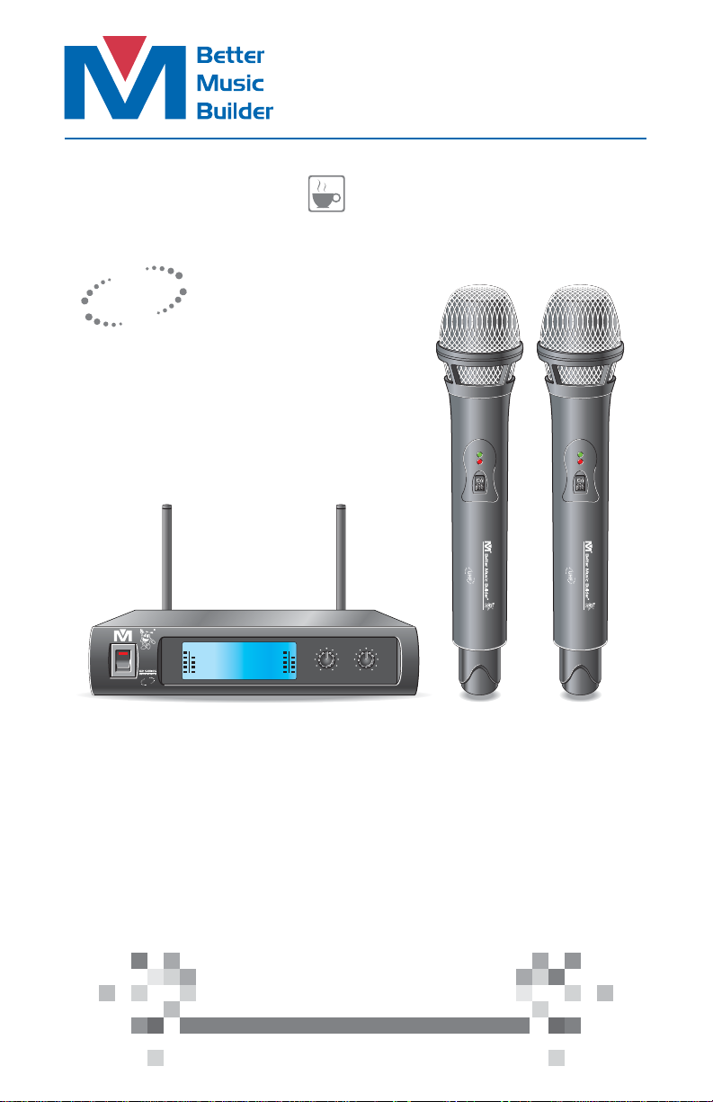
Professional UHF Wireless Microphone System
VM-52U G2
Operating Instructions
UHF
Frequency Selectable
®
Better Musi c Builder UHF W ire les s Sy ste m VM-5 2U G2 2-in-1 BAS E REC EIV ER MO DULE
RF AF RF AF
653.25
UHF
POWER
2-in-1 Base Module
ON
OFF
UHF WIRELESS SYSTEM VM-52U G2
CH
CH
01
02
556.00
MHz
MHz
1 Receive Module with 2 Wireless Microphones System
***
MIN MAX
MIC 1 VOLU ME
MIN MAX
MIC 2 VOLU ME
ON
OFF
UHF WIRELESS SYSTEM VM-52U G2
Thank you for purchasing this unit. To
make full and effective use of this unit,
please read this Owner's Manual
carefully before operating it. Please
retain this manual for future reference.
Passionate about Music
w ww .B et te rM us ic Bu il de r. co m
Page 2
CONTENTS
INTRODUCTION................................................................................ 1
Intro
SYSTEM FEATURES............................................................................. 1
Featur es
PACKAGE ACCESSORIES................................................................... 2
Packag e
2-in-1 BASE MODULE........................................................................ 3
Base Mo dule
• Controls and Functions................................................................. 3~4
• Hardware Setup............................................................................. 5~6
HAND-HELD MICROPHONE.............................................................. 7
hand- held
• Controls and Functions...................................................................... 7
OPERATION...................................................................................... 9
Opera tion
• How to Insert/change Batteries of Microphone.......................... 12
• How to Tell When Microphone is Ready to be Used................... 9
• How to Adjust Microphone Volume................................................ 9
• How to Turn On/Off Microphone................................................... 9
• How to Interchange Microphone Head.......................................... 9
TECHNICAL SPECIFICATION............................................................ 10
Spec
TROUBLESHOOTING.................................................................. 11~12
Troublesh ooting
APPENDIX....................................................................................... 13
Append ix
WARRANTY..................................................................................... 14
Warrant y
Page 3

INTRODUCTION
Intro
If you’re looking for simplicity, look no further! The Better Music Builder
VM-52U G2 Wireless Microphone is as streamlined as it gets without hindering
performance. It requires no setup as it is ready to go out of the box. Its light
weight design features dual wireless microphones and balanced XLR audio
signal to improve sound quality.
VM-52U G2 Wireless Microphone features Clear Voice, delivering crystal
clearer sound quality that pro audio engineers trust. Gone are unpleasant
artifact noises wireless microphones are known to emit. What you get is a
cleaner, clearer sound at all audio levels.
With years of experience designing wireless microphone system, we at Better
Music Builder understand the problem with short battery life. Through intensive
research we have developed a better power management system to help
extend our wireless microphone battery life.
Its predecessor VM-52U was our best-selling wireless microphone and we
believe VM-52U G2 will do the same.
SYSTEM FEATURES
Featu res
1. Equipped with the latest wireless technology and UHF dual-channel in a
2-in-1 Base Module to pick up weak signals and prevent signal interference.
2. Clear LCD screen displaying Frequency, Channel, Audio Frequency and
Radio Frequency.
3. Clear Voice delivering crystal clearer sound just like a wired microphone.
4. No setup required.
5. 6~8 hours of battery life.
6. Light weight mounting design for portability.
7. Adjustable antennas for better signal receiving.
8. AA battery usage for easy handling.
1
Page 4
PACKAGE ACCESSORIES
Packa ge
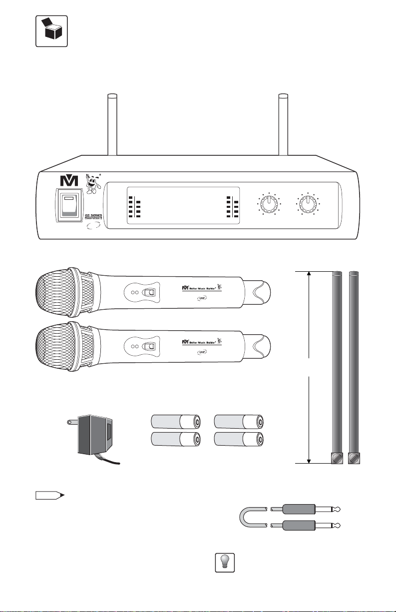
The package comes with one 2-in-1 Base Module [Receiver], two handheld
microphones, two receiver antennas, one DC adaptor, one unbalance audio
cable, and four AA batteries.
®
Better M usic Bu ilder U HF W irel ess Sys tem VM-52U G2
CH
RF AF RF AF
01
UHF
POW ER
HANDHELD MICROPHONE: SET of 2
DC POWER ADAPTOR: 1 UNIT
NOTE
DC-POWER USAGE: This wireless
microphone system is designed specifically
for the North American market, which uses
120V for DC power. For usage in Asia or
Europe, please change it to 220V by an
adaptor with DC 14V output 500mA.
653.25
2-IN-1 BASE MODULE [RECEIVER]: 1 SET
ON
OFF
ON
ON
OFF
ON
ALKALINE
BATTERY
ALKALINE
BATTERY
AA (1.5V) BATTERY: 4 UNITS
CH
02
556.00
MHz
UHF WIRELESS SYSTEM VM-52U G2
UHF WIRELESS SYSTEM VM-52U G2
AA
AA
2-i n-1 BASE RECE IVE R MOD ULE
MHz
MIN MAX
MIC 1 VO LUME
MIN MAX
MIC 2 VO LUME
6.5 inches
16.6 cm
ALKALINE
AA
BATTERY
ALKALINE
AA
BATTERY
RECEIVER
ANTENNA:
2 UNITS
AUDIO CABLE (FOR MIXED OUTPUT): 1 UNIT
For better quality connections, a XLR
to XLR cable is highly recommended.
Recommend
2
Page 5
2-in-1 BASE MODULE [RECEIVER]
Base Mo dule
CONTROLS AND FUNCTIONS
POW ER
®
UHF
Better M usic Bu ilder U HF W irel ess Sys tem VM-52U G2
CH
RF AF RF AF
01
653.25
556.00
MHz
CH
02
MHz
2-i n-1 BASE RECE IVE R MOD ULE
MIN MAX
MIC 1 VO LUME
MIN MAX
MIC 2 VO LUME
1 2 3 4
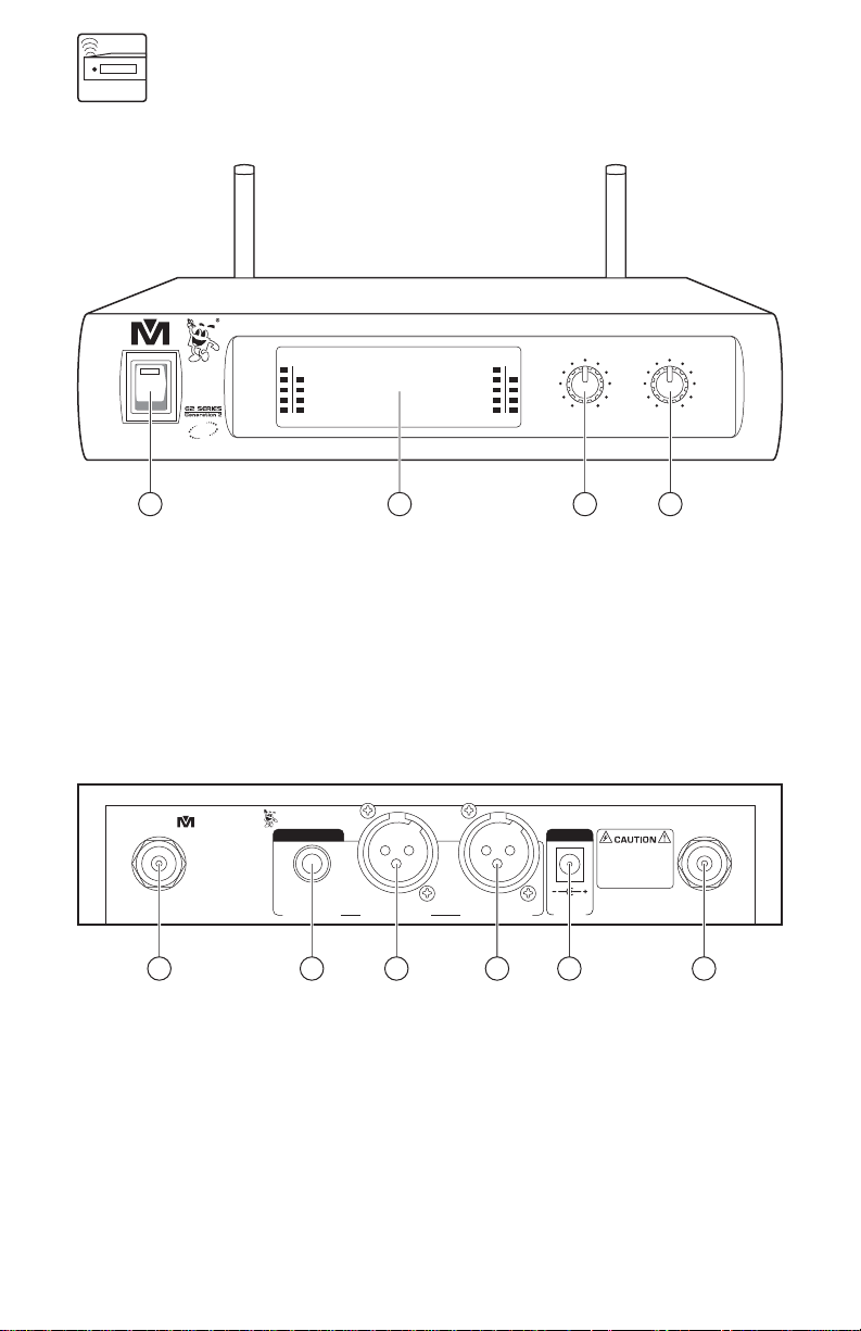
FRONT PANEL:
1. POWER SWITCH: Turns the system on/off.
2. LCD SCREEN: Displays system status.
3. MIC 1 VOLUME CONTROL: Controls Microphone 1 volume.
4. MIC 2 VOLUME CONTROL: Controls Microphone 2 volume.
®
Model N o.: VM-52U G 2
CALIFORNIA, UNITED STATES OF AMERICA
E-MAIL: sales@bet termusicbui lder.com
www .B et te rM us ic Bu il de r.c om
ENGINEERED AND DESIGN IN U.S.A.
364110806500
ANTENN A-A ANTENN A-B
Better Musi c Builder
(UHF Microphone)
®
AUD IO OU TPUT DC-POWER
TRUE D IVERSI TY
MIX
MIC 1 & 2
UNBALA NCED
MIC 2 BA LANCED MIC 1 BALA NCED
DC13~18V
500mA
SERIAL NO.:
RISK OF ELECTRIC SHOCK
DO NOT OPEN
Taking apart or modi fying
the receive r may lead to
electric sho ck, fire, or
damage to the re ceiver and
will void your wa rranty.
5 6 7 8 9 10
REAR PANEL:
5. ANTENNA-A: Connect the antenna to the BNC socket here.
6. MIXED OUTPUT: Unbalanced 1/4" audio output for MIC 1 & MIC 2.
7. MIC 2 BALANCED OUTPUT: Balanced XLR audio output.
8. MIC 1 BALANCED OUTPUT: Balanced XLR audio output.
9. POWER SUPPLY: Removable adapter with DC13-18V 500mA.
10. ANTENNA-B: Connect the antenna to the BNC socket here.
3
Page 6

LCD PANEL:
After turning on the “POWER” button, LCD screen will display the following:
RF AF RF AF
CH
01
653.25
1. MIC 1 RADIO FREQUENCY: Strength indicator of radio signal.
2. MIC 1 AUDIO FREQUENCY: Strength indicator of incoming audio signal.
3. MIC 1 FREQUENCY: Displays the current frequency.
4. MIC 1 CHANNEL: Displays the current channel.
5. MIC 2 FREQUENCY: Displays the current frequency.
6. MIC 2 CHANNEL: Displays the current channel.
7. MIC 2 RADIO FREQUENCY: Strength indicator of radio signal.
8. MIC 2 AUDIO FREQUENCY: Strength indicator of incoming audio signal.
MHz
4 61 2 7 83 5
CH
02
556.00
MHz
4
Page 7
HARDWARE SETUP
Set Up
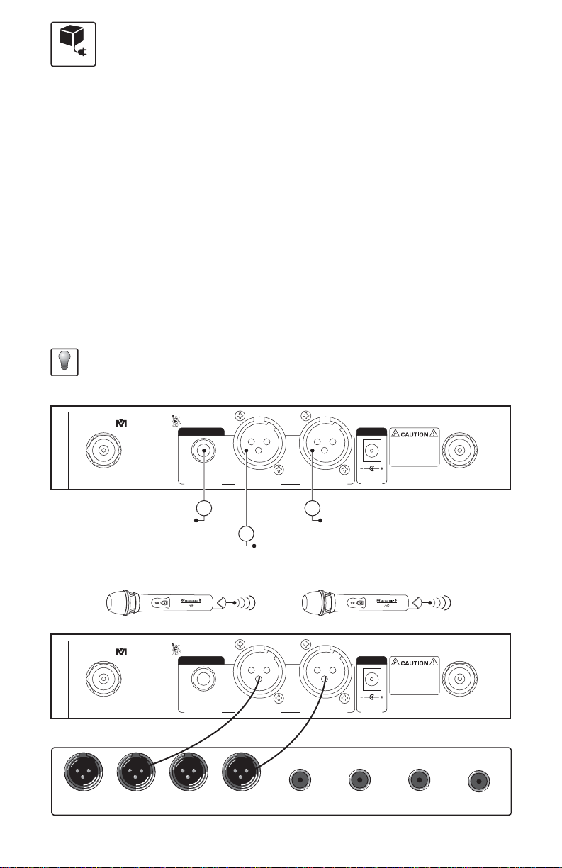
HOW TO CONNECT AUDIO OUTPUT:
There are three rear outputs as shown in the below diagram:
MIXED OUTPUT is unbalanced audio output for MIC 1 & MIC 2 using 1/4”
connection. When using this output, MIC 1 and MIC 2 have to share a signal. To
produce different effects on each microphone, MIC 1 and MIC 2 need their own
signals which can be done by using XLR connections.
MIC 1 BALANCED OUTPUT is balanced audio output for MIC 2 using XLR
connection. When using this output, you can change MIC 2 effects without
affecting MIC 1 effects.
MIC 2 BALANCED OUTPUT is balanced audio output for MIC 2 using XLR
connection. When using this output, you can change MIC 2 effects without
affecting MIC 1 effects.
We highly recommend using balanced XLR connections if the distance between the
microphone receiver and the amplifier/mixer is more than 10 feet. The grounding of the
Recommend
balanced XLR connection delivers better quality signal by reducing noise.
®
Model N o.: VM-52U G 2
CALIFORNIA, UNITED STATES OF AMERICA
E-MAIL: sales@bet termusicbui lder.com
www .B et te rM us ic Bu il de r.c om
ENGINEERED AND DESIGN IN U.S.A.
364110806500
ANTENN A-A ANTENN A-B
MIXED OUTPUT
(MIC 1 & 2 UNBALANCED)
Better Musi c Builder
(UHF Microphone)
®
AUD IO OU TPUT DC-POWER
TRUE D IVERSI TY
MIX
MIC 1 & 2
UNBALA NCED
MIC 2 BA LANCED MIC 1 BALA NCED
1
3
MIC 1 BAL ANCED OUTPUT (BALANCED XLR)
2
DC13~18V
500mA
MIC 2 BAL ANCED O UTPUT (BALANCED XLR)
UHF WIRELESS SYSTEM DIAGRAM:
UHF WIRELESS SYSTEM VM-52U G2
ON
MIC 1 HANDHELD MICROPHONE
®
Model N o.: VM-52U G 2
CALIFORNIA, UNITED STATES OF AMERICA
E-MAIL: sales@bet termusicbui lder.com
www .B et te rM us ic Bu il de r.c om
ENGINEERED AND DESIGN IN U.S.A.
364110806500
ANTENN A-A ANTENN A-B
Better Musi c Builder
(UHF Microphone)
®
AUD IO OU TPUT DC-POWER
TRUE D IVERSI TY
MIX
MIC 1 & 2
UNBALA NCED
MIC 2 BA LANCED MIC 1 BALA NCED
REAR VIEW
XLR
Balanced Input
XLR
Balanced Input
XLR
Balanced Input
XLR
Balanced Input
MIC 2 HANDHELD MICROPHONE
BALANCED CONNECTION
1/4"
Unbalanced Input
Unbalanced Input
AUDIO MIXER AMPLIFIER OR A KARAOKE UNIT INPUT TERMINAL
5
ON
DC13~18V
500mA
1/4"
UHF WIRELESS SYSTEM VM-52U G2
SERIAL NO.:
RISK OF ELECTRIC SHOCK
DO NOT OPEN
Taking apart or modi fying
the receive r may lead to
electric sho ck, fire, or
damage to the re ceiver and
will void your wa rranty.
SERIAL NO.:
RISK OF ELECTRIC SHOCK
DO NOT OPEN
Taking apart or modi fying
the receive r may lead to
electric sho ck, fire, or
damage to the re ceiver and
will void your wa rranty.
1/4"
Unbalanced Input
1/4"
Unbalanced Input
Page 8
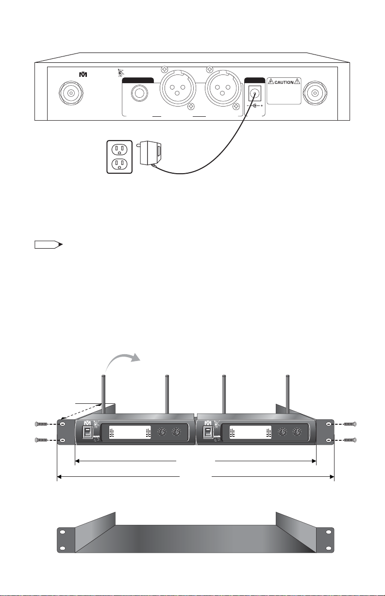
HOW TO CONNECT DC-POWER:
®
Model N o.: VM-52U G 2
CALIFORNIA, UNITED STATES OF AMERICA
E-MAIL: sales@bet termusicbui lder.com
www .B et te rM us ic Bu il de r.c om
ENGINEERED AND DESIGN IN U.S.A.
364110806500
ANTENN A-A ANTENN A-B
Better Musi c Builder
(UHF Microphone)
®
AUD IO OU TPUT DC-POWER
TRUE D IVERSI TY
MIX
MIC 1 & 2
UNBALA NCED
MIC 2 BA LANCED MIC 1 BALA NCED
DC13~18V
500mA
SERIAL NO.:
RISK OF ELECTRIC SHOCK
DO NOT OPEN
Taking apart or modi fying
the receive r may lead to
electric sho ck, fire, or
damage to the re ceiver and
will void your wa rranty.
REAR VIEW
For North America Market, use 120V, DC 14~22V 500mA adaptor. For market
outside North America, use 220V~ 240V DC adaptor with a maximum battery
capacity of 500mA.
NOTE
Please make sure to use the right DC adaptor. Otherwise, it may damage the 2-in-1 Base
Module and the charger because their maximum battery capacity is different. The product
warranty will be voided if there is damage caused by using the wrong DC adaptor.
OPTIONAL 19” RACK MOUNT KIT:
To put the system onto a mount-kit, please follow the diagram below. Our
special design allow it to be mounted on a DJ rack.
10 inches
®
UHF
POWER
ANTENNA IS ADJUSTABLE
Better Music Buil der UHF Wi rel ess Sys tem VM-52U G2
CH
CH
RF AF RF AF
01
02
653.25
556.00
MHz
MHz
Rack mount kit is not included in package.
2-in-1 BASE REC EIVE R MOD ULE
MIN MAX
MIN MAX
MIC 2 VO LUME
MIC 1 VO LUME
POWER
13.8 inches
19 inches
6
®
Better Music Buil der UHF Wi rel ess Sys tem VM-52U G2
RF AF RF AF
653.25
UHF
MHz
CH
02
556.00
MHz
2-in-1 BASE REC EIVE R MOD ULE
MIN MAX
MIN MAX
MIC 2 VO LUME
MIC 1 VO LUME
CH
01
Page 9
HANDHELD MICROPHONE
Hand-held
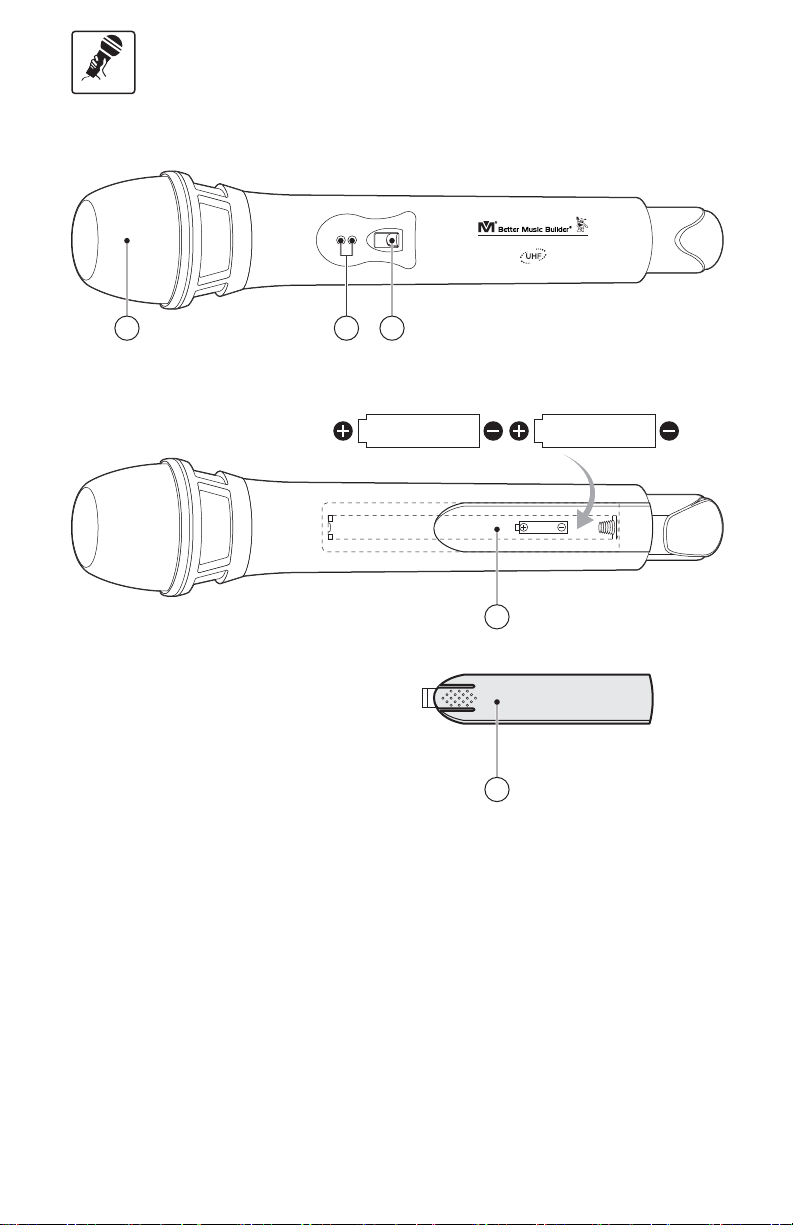
CONTROLS AND FUNCTIONS
ON
1 3
2
ON
AA
OFF
ALKALINE
BATTERY
UHF WIRELESS SYSTEM VM-52U G2
AA
2x1.5V
4
5
ALKALINE
BATTERY
1. INTERCHANGEABLE MICROPHONE HEAD
2. POWER INDICATOR LED: Flashes when batteries are low.
3. POWER SWITCH: Powers ON/OFF and MUTE.
4. BATTERY COMPARTMENT: Insert two 1.5V AA batteries or two 1.2V
rechargeable batteries .
5. VARIABLE BATTERY COVER
7
Page 10
OPERATION
Oper ation
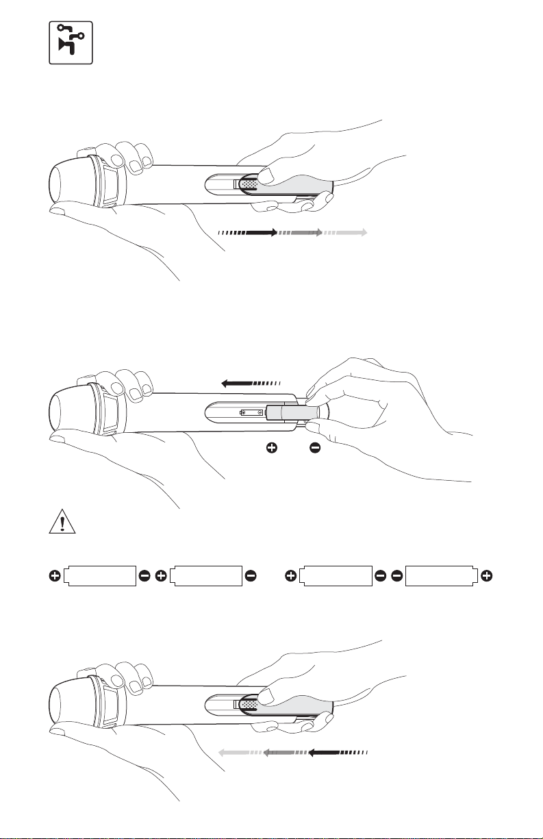
HOW TO INSERT/CHANGE BATTERIES OF MICROPHONE
STEP 1: Slide open battery cover.
2x1.5V
STEP 2: Hold the top of the microphone with one hand and with the other hand
slide two AA batteries into the battery compartment. Be careful not to drop
microphone while inserting batteries.
AA
ALKALINE
BATTERY
2x1.5V
Make sure to follow the polarity of the battery according to the diagram.
AA
ALKALINE
BATTERY
Good
AA
ALKALINE
BATTERY
AA
No Good
ALKALINE
BATTERY
ALKALINE
BATTERY
AA
STEP 3: Slide back battery cover.
2x1.5V
8
Page 11
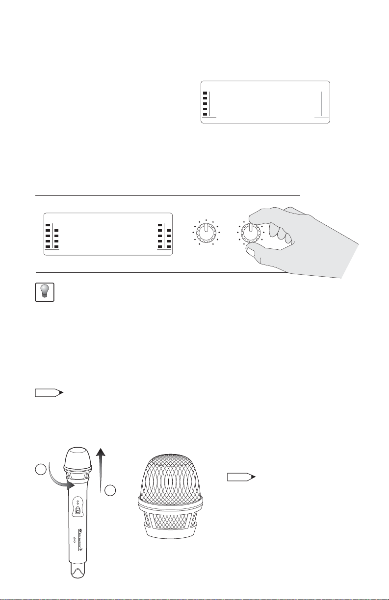
HOW TO TELL WHEN MICROPHONE IS READY TO BE USED
After turning on the handheld microphone, pay attention to the RADIO
FREQUENCY (RF) on the receiver’s LCD SCREEN.
RADIO FREQUENCY (RF) bars indicate
that the microphone is ready for usage.
RF AF RF AF
CH
01
653.25
556.00
MHz
CH
02
MHz
HOW TO ADJUST MICROPHONE VOLUME
Turn the VOLUME CONTROL knob: LEFT to decrease the volume and RIGHT to
increase the volume.
Bette r Music B uild er UH F W ire less Sy ste m V M-52U G2 2 -in -1 BA SE RE CEIV ER M ODUL E
RF AF RF AF
CH
01
653.25
We recommend setting the microphone volume to the center position, then control the
overall volume from the amplifier/mixer.
Recommend
556.00
MHz
CH
02
MHz
MIN MAX
MIC 1 VO LUME
MIN MAX
MIC 2 VO LUME
HOW TO TURN ON/OFF MICROPHONE
TURN ON: Slide the power switch to the top to turn the power on.
TURN OFF: Slide the power switch to the bottom to turn the power off.
MUTE: Slide the power switch to the middle to mute the vocal.
NOTE
If the microphone cannot be turned on, batteries may be low. Battery life is typically 6
hours. Battery life may vary depending on battery type and usage. Batteries are not covered
under our product warranty.
HOW TO INTERCHANGE MICROPHONE HEAD
1
2
ON
ON
OFF
UHF WIRELESS SYSTEM VM-52U G2
INTERCHANGEABLE
MICROPHONE HEAD
9
NOTE
Replacement parts (such as the
microphone head as shown on the
left) can be purchased from any of
our authorized dealers.
Page 12

TECHNICAL SPECIFICATION
Spec
A. TECHNICAL FEATURE OF THE 2-IN-1 BASE MODULE:
1. Channels: 2
2. Frequency Range: UHF 520~700 MHz
3. Maximum Frequency Deviation: ±45KHz
4. Sensitivity: 2.0uV
5. Sensitivity Adjustment Range: 12~32dB BUV
6. Frequency Response: 35Hz~20kHz +/-3dB
7. Audio Output Level: Balanced Output: 0~0.5V/100
Sound Output: 0~0.5V/5K
8. Stay Control: >75dB
9. Consume Power: 5 Watts
10. Power Supply: DC 13V~18V with 500mA, AC 120V (For 220V, you may
need to change to a 220V~240V DC adaptor)
11. Receiver Dimensions (WxHxD): 8.3 x 2 x 8.1 (inches) / 21 x 5 x 20.5 (cm)
12. Package Dimensions (WxHxD): 18.5 x 14.6 x 3.7 (inches) / 47 x 37 x 9.5 (cm)
13. Shipping Weight: 6.4 lbs / 2.9 kg
B. TECHNICAL FEATURE OF THE MICROPHONE:
1. Transmitter Power: 10mW
2. Osillation Mode: PLL
3. Adjustment Mode: FM
4. Image Controlment: >50dB
5. Adjust Frequency Deviation: <75kHz
6. Battery Voltage: 2 x AA 1.5V Alkaline Batteries
7. Continuous Using: 6~8 Hours (GP) 2 x AA 1.5V Batteries
8. Microphone Dimensions (WxH): 10.3 x 2.2 (inches) / 26.1 x 5.5 (cm)
C. THIS SYSTEM INCLUDES THE FOLLOW:
• 2-in-1 Base Module: 1 Set • DC-Power Adaptor: 1 Unit
• Handheld Microphone: 2 Sets • Audio Cable: 1 Unit
• Antenna: 2 Units • Instructional Manual: 1 Unit
• AA 1.5V Battery: 4 Units
10
Page 13

TROUBLESHOOTING
Troublesh ootin g
CAUTION: Before troubleshooting any symptoms, make sure equipments
are turned OFF.
1. SYMPTOM: NO SOUND
CAUSE: There is no indication of signal.
REMEDIES:
A. Batteries should be inserted correctly. Make sure to follow the polarity of
the battery according to the diagram.
B. If batteries are inserted correctly and still no power, batteries may be low
and should be replaced.
C. Microphone and receiver should be in the same channel to allow
transmitting and receiving signal.
D. Volume is turned to a low level and should be turned to a high enough but
comfortable volume level.
E. Make sure no wires inside the microphone are loose. If it is, reconnect
wires if possible.
F. Make sure the microphone is turned ON; not OFF or set to MUTE.
2. SYMPTOM: RECEIVER LCD IS OFF.
CAUSE: Receiver is unpowered.
REMEDIES:
A. Power adapter should be connected properly.
B. Make sure the right power adapter is being used.
C. Determine whether there is indeed current coming from the power outlet.
3. SYMPTOM: NOISES.
CAUSE: There is interference within your area.
REMEDIES:
A. Make sure user isn’t standing too close to speakers. Standing too close to
speakers with microphone will create feedback unless microphone volume
is turned down.
11
Page 14

B. Audio cable of poor quality should not be used. Switching to a cable of
higher quality such as a balanced XLR cable can reduce noise.
C. Switch to a model that uses a different set of channels when the above
remedies do not work.
4. SYMPTOM: DISTORTION IS INCREASING GRADUALLY.
CAUSE: Batteries are running low.
REMEDIES:
A. Replace batteries as soon as possible.
B. Make sure batteries have enough power. Even if they are new batteries,
they may have lost power during its time being on the store shelves.
5. SYMPTOM: POOR SIGNAL.
CAUSE: Objects can be disrupting communication between receiver and
microphone.
REMEDIES:
A. Make sure no objects are between receiver and microphone, such as walls
and shelves.
B. Make sure microphone usage is not in perimeter of police, fire or radio
stations.
C. Devices that send out radio signals can be disruptive, such as cell phones,
radios, computers, etc.
D. Switch to a model that uses a different set of channels when the above
remedies do not work.
12
Page 15

APPENDIX
Appen dix
VM-52U G2 FCC FREQUENCY: 520.000~700.000 MHz
UHF Frequencies Available for Use for Home Electronics in North America
The RF radio frequencies used in the transmission of wireless information are
closely regulated in most countries including North America. A lot of countries
strictly enforce their regulations stating which RF frequencies are available for
use for certain device, so it can help limit the amount of radio frequency
interference in all wireless communications.
Please refer to the following table for MIC 1 and MIC 2 with available RF
frequencies. If the RF frequencies indicated in the following table are in conflicts
with the local wireless information law in your country, please switch to a
different product model or contact our technicians for advice.
FCC Information to User for Reference
This equipment is designed in compliance with the limits for a Class A digital
device pursuant to part 15 of the FCC Rules from the United States of America.
These limits are designed to provide protection against harmful interference
when the equipment is operated in public environment. This equipment
generates, uses, and can radiates radio frequency energy and, if not installed
and used in accordance with the instruction manual, may cause harmful
interference to radio communications. Operation of this equipment in a
residential area may cause harmful interference, so the user will have to correct
the interference at his/her own expense.
13
Page 16
WARRANTY
Warran ty
One-Year Limited Warranty for Home Use Equipment
Our one-year warranty applies to speakers, amplifiers, mixers and microphones for
home use only. It covers both parts and labors. The warranty becomes effective on
the date of your purchase.
Our warranty only covers defects due to product defectiveness with free of defects
in materials or workmanship. However, our warranty does not cover defects due to
normal wears, damage in transit, improper use, abuse or failure to follow the proper
instructions for maintenance. This warranty is void in the event of unauthorized
repairs, alternations, modifications and removing of the product label.
Please also note that our warranty does not cover any shipping cost for the return of
defective products to us for inspection, repair and maintenance. Our warranty for
Better Music Builder products can only be executed in North America.
Our warranty does not cover the battery for wireless microphone products.
NOTE
90-Day Limited Warranty for Public and Commercial Use Equipment
Our 90-day warranty applies to speakers, amplifiers, mixers and microphones for
both public and commercial use such as restaurant, coffee shop, KTV nightclub,
church and school, etc. It covers both parts and labors. The warranty becomes
effective on the date of your purchase.
To Register Your Warranty
Please submit the warranty card that cames with your unit; it is also download on
our website . However, we need the invoice for your purchase in order to process
this warranty. You may also register your warranty online.
Please visit our website at ww w.B e tte r Music B ui lder.c o m.
PRECAUTION
1. If using more than one microphone system, please select the operating
frequency or signal channel carefully so as to avoid disturbing.
2. The input power voltage of the 2-in-1 Base Module is 110V/120V (±10%). If it is
too low or too high, it will affect the work of the machine.
3. When installing batteries, reversing the electrode will damage the machine.
This symbol, wherever it appears, alerts
RISK OF ELECTRIC SHOCK
DO NOT OPEN
Caution: To reduce the risk of electrical shock, do not
remove the cover (or back). No user serviceable parts
inside: refer servicing to qualified personnel.
Warning: To reduce the risk of fire or electrical shock,
do not expose this appliance to rain or moisture.
14
you to the presence of uninsulated
dangerous voltage inside the enclosure
voltage that may be sufficient to
constitute a risk of shock.
This symbol, wherever it appears, alerts
you to important operating and
maintenance instructions in the
accompanying literature. Read the
manual.
Page 17

MAINTENANCE
NOTE
15
Page 18
Better Music Builder is a leader in the Audio and
Karaoke equipment industry. We are committed
to offering you high quality audio products. We
may update our manual, so we highly
recommend you to download the free update
from our website at www.BetterMusicBuilder.com.
®
®
Unlike any others ... that’s cost & value for you
Passionate about Music
w w w . B e t t e r M u s i c B u i l d e r . c o m
364110806500
Code: 20110901
Printed on 100% Recycled Paper Comment s E-mail to sales@bett ermusicbuilder.com C opyright © 2011 Bet ter Musi c Builde r. All rights reser ved. Leg al trade mark.
 Loading...