

Page 1
HANDLE SET INSTALLATION-W&F ENTRY HARDWARE
Overview
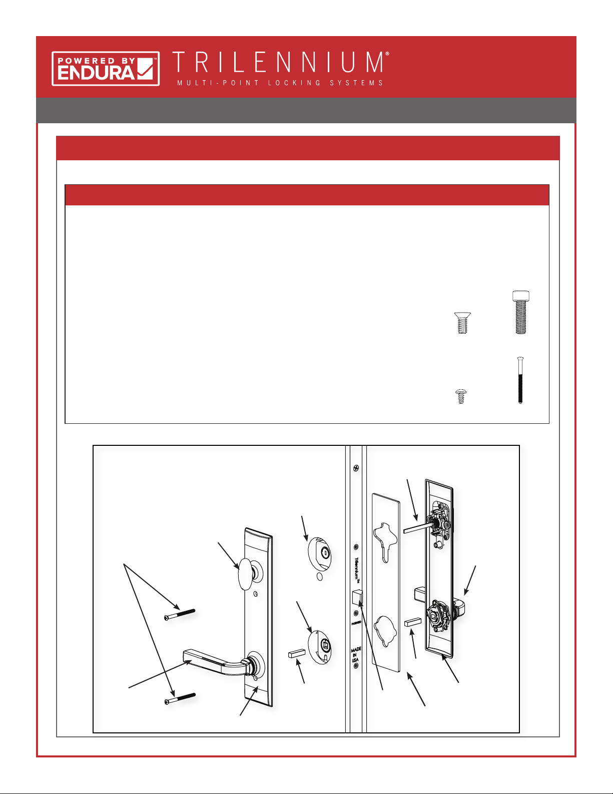
Check contents and identify all parts before proceeding
PARTS INCLUDED FOR NON-GRIP HANDSETS
Interior Escutcheon: (1) Individually Packed
Exterior Escutcheon: (1) Individually Packed
(1) Escutcheon Gasket
Handle Pack: (2) Lever Handles
Cartridge Pack: (1) Left Handed Handle Return Cartridge
(1) Right Handed Handle Return Cartridge
(4) #6-32 x 1/4" Phillips Head Cartridge Mounting Screws
(2) #10-32 Allen Screws for Handles
(1) 9/64" Allen Wrench
Key Cylinder Pack: (1) Key Cylinder with (2) Keys
(2) Drive Rods
(1) #8 x 3/8" Self Tapping Screw
(2) #10-32 Mounting Screws
#6-32 x 1/4" Phillips
Head Cartridge
Mounting Screws (4)
#8-3/8" Self-
Tapping Screw (1)
#10-32 Allen Screws
for Handles (2)
#10-32 Mounting
Screws (2)
™
#10 x 32 Mounting
Screws
Interior
Lever
Handle
Thumbturn
Interior
Escutcheon
Deadbolt
Hub
Lever Hub
Spindle
Key Cylinder
Tailpiece
Exterior
Lever Handle
Spindle
Exterior
Escutcheon
Deadbolt
Exterior Escutcheon
Gasket
1
Page 2
HANDLE SET INSTALLATION-W&F ENTRY HARDWARE
™
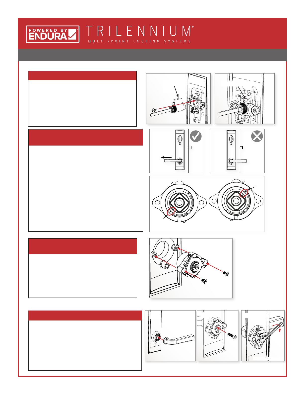
1. PREPARE EXTERIOR ESCUTCHEON
a. Remove key from lock cylinder.
b. Insert lock cylinder into upper hole from
back side of escutcheon plate with tab
pointing up. Orient as shown.
c. Secure lock cylinder with # 8 x 3/8" self-
tapping screw.
2. DETERMINE THE PROPER HANDING OF
YOUR HANDSETS
a. Identify the handset lever handing on each side
of the panel.
b. On the escutcheon where the lever points
towards the left, use the left hand (LH) cartridge.
c. On the escutcheon where the lever points
towards the right, use the right hand (RH)
cartridge.
1
Tab should
be up
2a
Lever Pointing
Away from Lock
2b
Arrow
pointing
to L
Left Handed Cartridge Right Handed Cartridge
Self-tapping screw
2c
Arrow
pointing
to R
3. ATTACH THE CARTRIDGE TO THE
ESCUTCHEON
a. Once the proper cartridge for your handset
is determined, insert the cartridge into the
back of the escutcheon and secure with the
two #6-32 x 1/4" Phillips Head Cartridge
Mounting Screws.
4. ATTACH THE LEVERS TO THE ESCUTCHEON
a. Insert the handle into square recess in
spindle and hold in place.
b. Insert the handle mounting screw into the
center of the cartridge and hand tighten
with the Allen Wrench provided.
c. Pull the lever tight against the cartridge to
ensure that it is fully tightened.
3
4a
4b
4c
Back of Escutcheon Back of EscutcheonFront of Escutcheon
2
Page 3
HANDLE SET INSTALLATION-W&F ENTRY HARDWARE
™
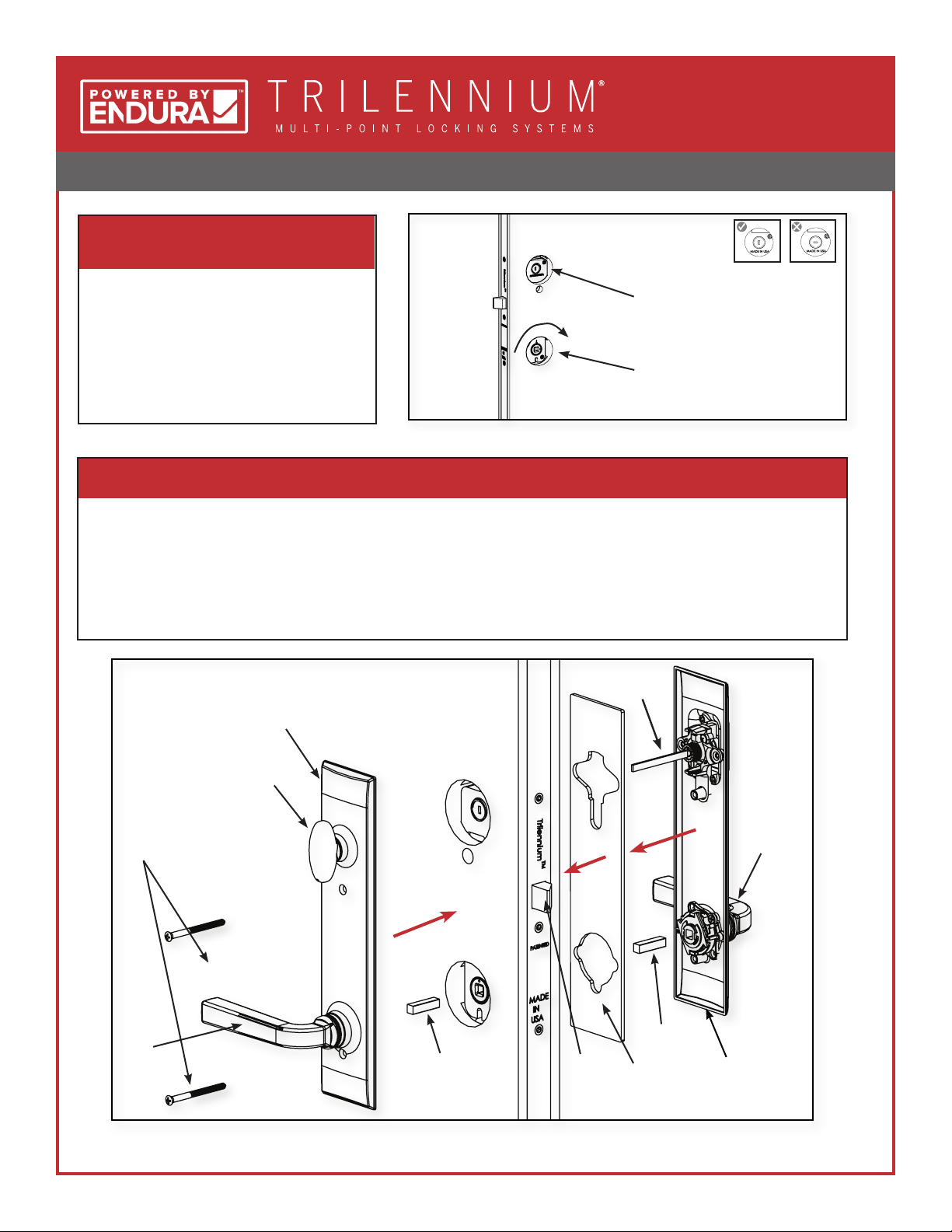
5. CHECK HARDWARE IN DOOR FOR
5
ALIGNMENT OF HUB
a. Open door by turning the lever
hub of the lock
b. Deadbolt slot must be vertical
c. Bolts must be in the latched (not
deadbolted) position
Vertical
Vertical
Deadbolt Slot
Turn to open
Slot
Horizontal
Slot
6. POSITION ESCUTCHEONS TO DOOR PANEL
a. Exterior rst: Place Escutcheon Gasket over inside face of escutcheon. Guide Cylinder Tailpiece and Spindle
into respective hubs in hardware. Reference diagram below.
b. Hold in place
c. Interior next: Make certain that receiving slot in thumbturn lines up with the Cylinder Tailpiece.
d. Secure with (2) #10-32 Mounting Screws from interior to exterior. Hand-tighten snug. DO NOT OVERTIGHTEN
Key Cylinder
Interior
Escutcheon
Tailpiece
#10 x 32 Mounting
Screws
Interior
Lever
Handle
Thumbturn
Spindle
Deadbolt
Spindle
Exterior
Escutcheon
Gasket
Exterior
Lever
Handle
Exterior
Escutcheon
3
Page 4
HANDLE SET INSTALLATION-W&F ENTRY HARDWARE
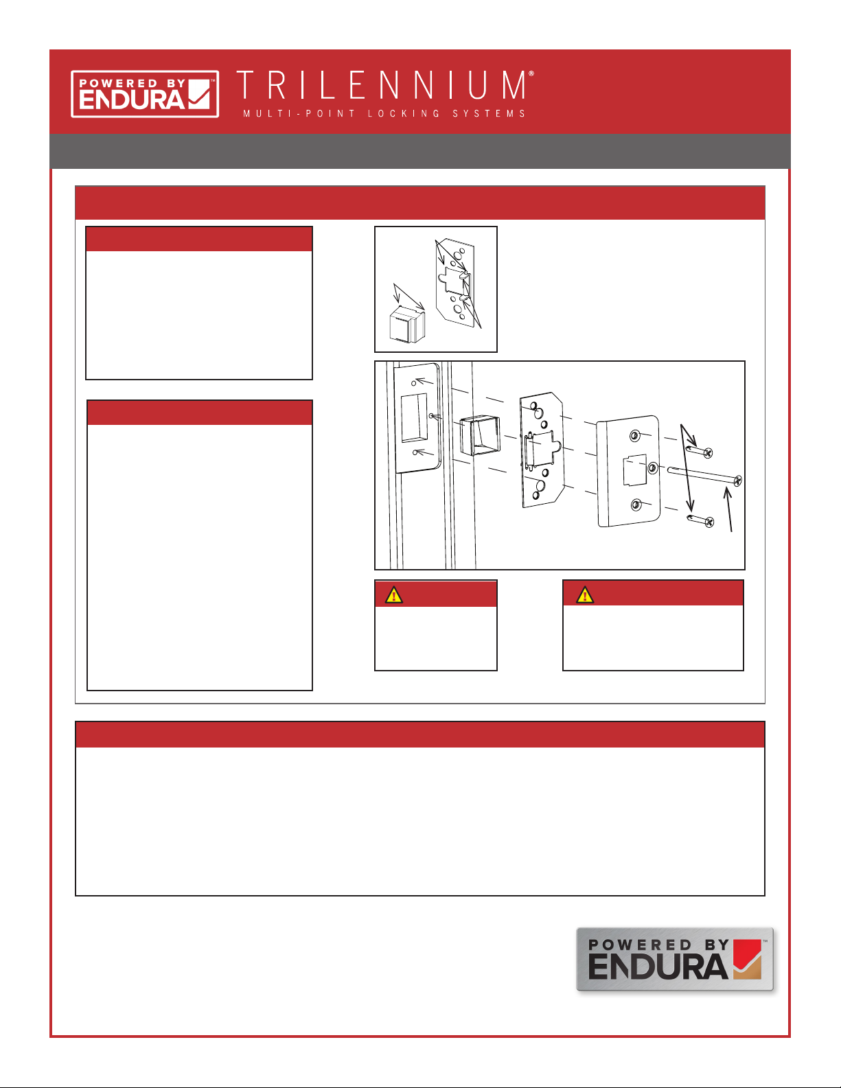
7. STRIKE PLATE ASSEMBLY (IF NOT ALREADY COMPLETE)
™
Parts Required
• (3) Dust Boxes
• (3) Reinforcing Plates
• (3) Strike Plates
• (6) 3/4" screws
• (3) #10 x 2-1/2" screws
Attach strike plates to jamb.
a. Attach the Dust Box to the
Reinforcing Plate.
b. Align the 3 holes on the Strike
Plate with the Reinforcing Plate.
c. Orient as shown.
d. Use 3/4" screws in top and
bottom holes of each strike.
e. Use long #10 x 2-1/2" Screw in
center hole.
f. Repeat for remaining strike
locations.
Slots for Dust Box Feet
Dust Box
Feet
Reinforcing
Plate Arms
Note
A Ø1/8" pilot hole
should be drilled into
the rough framing for
the long screw.
• The Dust Box Feet should align with the slots in the
reinforcing plate.
• The reinforcing plate arms should sit inside the dust
box.
Dust Box
Strike Plate
3/4" Screws
Reinforcing Plate
#10 x 2-1/2"
Screw
Note
Solid shimming should be
placed behind the jamb at each
strike location to allow for rm
anchoring to structure.
8. FINAL OPERATION CHECK
a. All three latch bolts should engage strikes as door is closed.
b. Turn thumbturn 90° to extend all three bolts an additional 1/2" to deadbolted position.
c. Rotate interior lever downward to disengage bolts and open door. Bolts can also be moved to latched
position by turning thumbturn.
d. Engage deadbolt again. From the exterior, conrm that the lever cannot rotate and disengage the
latches (door is deadbolted). Conrm that the door can be unlocked with the key and then opened by
rotating the lever downward.
U.S. Patents Pending
The information contained in this document is the condential and proprietary information and trade secrets of Endura Products, Inc. Any disclosure,
use or dissemination of such information without the express written permission of Endura Products, Inc. is strictly prohibited. Endura Products, Inc.
also owns any and all intellectual property rights embodied in such information, including patent rights, copyrights, and trademark rights, and no
license of any intellectual property right is intended, nor should any license be implied, as a result of the receipt of this document.
Rev. 03.15.2017
1.800.334.2006 www.enduraproducts.com
8817 W. Market St., Colfax, NC 27235
4
 Loading...